Creating a Floor plan, Footing detail and Isometric view using AutoCad
P-1
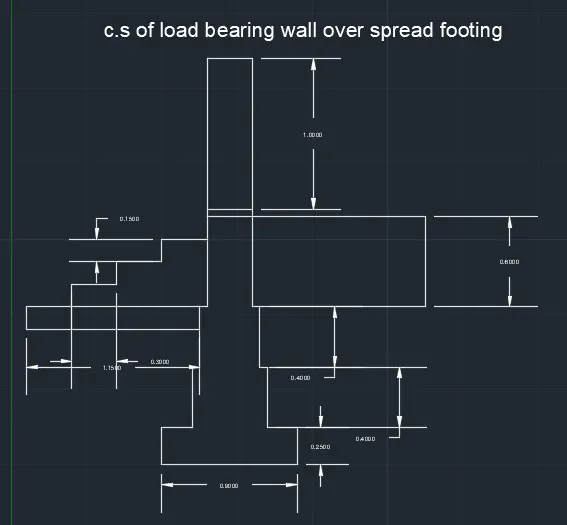
C.S OF LOAD BEARING WALL OVER SPREAD FOOTING.
Aim ,
To draw a cross section of load bearing wall over spread footing.
Procedure ,
* First of all set the limits and units as per the requirements.
* Using line command set the first point as (1,1).
* Then create a diagram using given measurements.
* Then using dimlinear option to measure the diagram.
Diagram ,
P-2
Aim ,
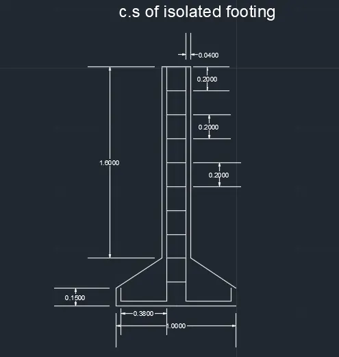
To create a cross section of isolated footing.
Procedure ,
* First of all set the limits as per your requirements.
* Then using line command , draw the isolated footing using given measurements.
* offset the points of 0.04 from the left and right of the drawing.
* Then using dimlinear measure the measurements.
Diagram ,
P-3
Aim ,
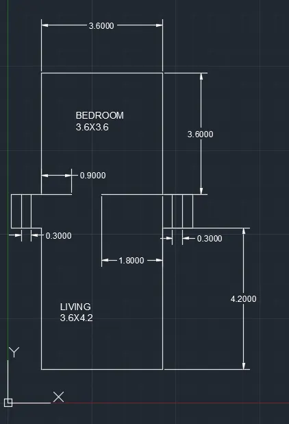
To draw a line diagram of a two bedroom building uding autocad.
Procedure ,
* First set the limits in the autocad.
* Then using line command draw the diagram using given measurements.
* Using dim linear command, measure the diagram drawn.
Diagram ,
P-5
Aim ,
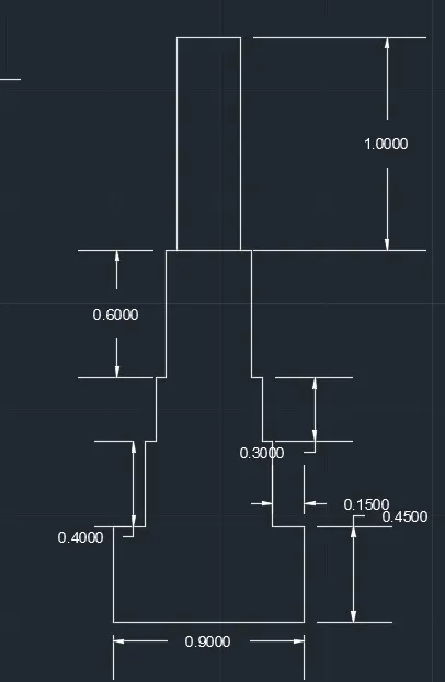
To draw the cross section of a load bearing wall showing foundation details.
Procedure ,
* Set the limits in autocad.
* Using line command give the first point as 1,1.
* Then draw the diagram using given measurements.
* Then measure the drawing using dimllinear
Diagram ,
P-6
Aim ,
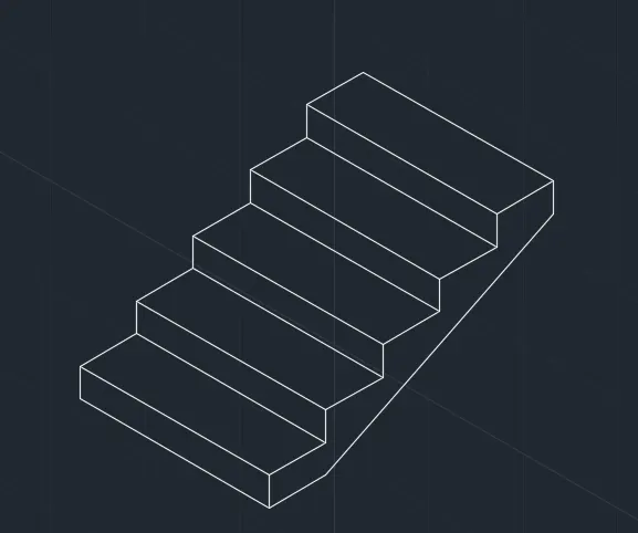
To draw a isometric view of steps.
Procedure ,
* First set the limits in the autocad.
* Then correct the units and make it zoom.
* Then on the "isometric snap" in the grid option.
* Then draw the steps in the autocad using given measurements.
Diagram ,
P-7
Aim ,
To draw a isometric view of gable wall.
Procedure ,
* First set the limits in the autocad.
* Then correct the units and make it zoom.
* Then on the "isometric snap" in the grid option.
* Then draw the Gable wall in the autocad using given measurements.
Diagram ,