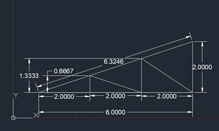
Creation of geometries by Coordinate system methods using AutoCad
Create the geometries from P1 to P2 using all the coordinates system methods. You need to use the Line tool to create the geometries. Where required you need to use the circle tool.
Please read the drawings and find out the missing dimensions before working on the sketches.
AIM :
Create the geometries from P1 to P2 using all the coordinates system methods. You need to use the Line tool to create the geometries.
CO ORDINATE SYSTEMS :
* Absolute co ordinate system
* Relative co ordinate system
* Polar coordinate system
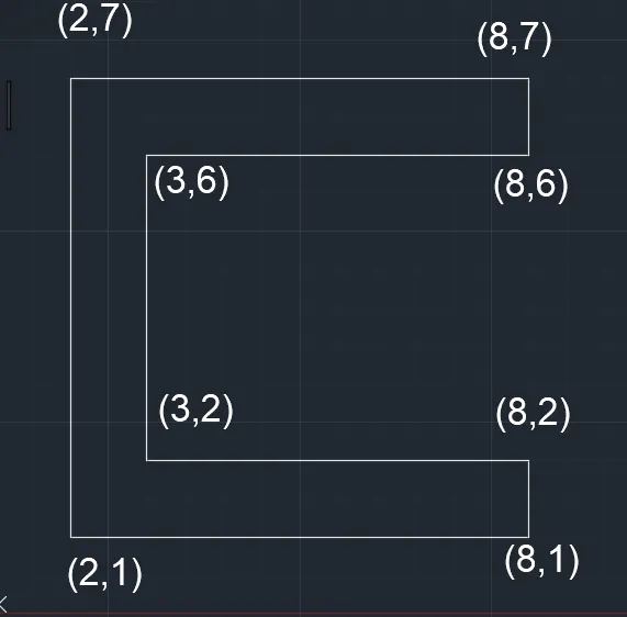
ABSOLUTE COORDINATE SYSTEM.
PROCEDURE :
* First set the autocad units.
* Then in the command line type line command
* Specify the first point as (2,1).
* Then draw the line using second point #8,1
* Then upward #6,2
* Then leftward #3,2
* Then upward as #3,6 and next as #8,6 and #8,7
* Then #2,7
* Then close it.
DIAGRAM :
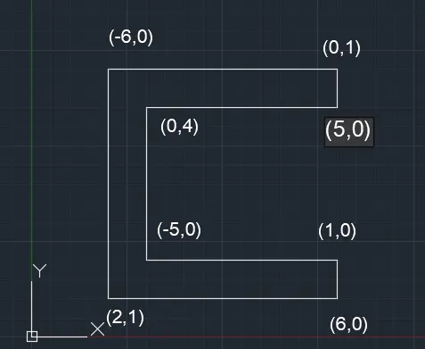
RELATIVE COORDINATE SYSTEM.
PROCEDURE :
* In relative coordinate system the first point is not calculated from the origin.
* Set the first point as (2,1).
* Then set the second point as (6,0) and next (1,0).
* Then we need minus point so (-5,0).
* Then next points as (0,4) , (0,5) , (0,1) and (-6,0).
* Then close it.
DIAGRAM :
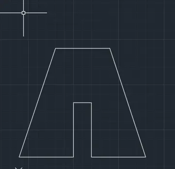
P2
ABSOLUTE COORDINATE SYSTEM
PROCEDURE.
* First enter line command and set the point as(2,1)
* Then next point #5,1 and next as #5,5 .
* Then other points as #6,5 ; #6,1 ; #9,1 ; #7,8 and #4,8 .
* Then close it.
Diagram.
RELATIVE COORDINATE SYSTEM
PROCEDURE :
* First set the point as (2,1)
* Then @ 3,0 and using @ in every point.
* Then fix the coordinates as (0,4) , (0,1) the (0,-4) and (0,3)
* Then (7,2) upper and close it.
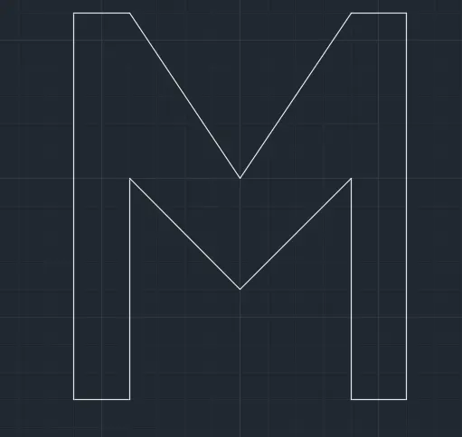
P-4
Aim ,
To draw a m shape using any co ordinate method.
Procedure ,
* Set a limits first on Autocad
* Then set a first point as (2,1).
* Then using line command @0,7 and @1,0 and @2,-3 for upper side
* Then from the starting point @1,0 and @0,4from the below. We get one side of the M
* Then mirror it.
Diagram ,
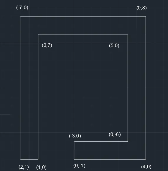
P-5
Aim ,
To draw the given picture in the Autocad using any method.
Procedure ,
* First set the point as (2,1)
* Then type using line command the following marks using @ at first,
(1,0) , (0,7) , (5,0) , (0,-6) , (-3,0) , (0,-1) , (4,0) , (0,8) , (-7,0)
* Then close it.
Diagram ,
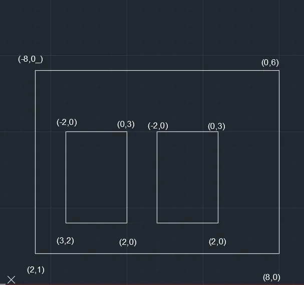
P-7
Aim ,
To draw a given diagram using any co ordinate method
Procedure ,
* First set the point as (2,1)
* Then using @ , (8,0) , (0,6) , (-8,0) and close it to finish the first rectangle.
* Then set the point as (3,2) and using @ (2,0) , (0,3) , (-3,0) then close it to finish the inner rectangle.
* Then repeat the propcedure from distance of 1 from the point (2,0) then finish the secomnmg rectangle.
Diagram ,
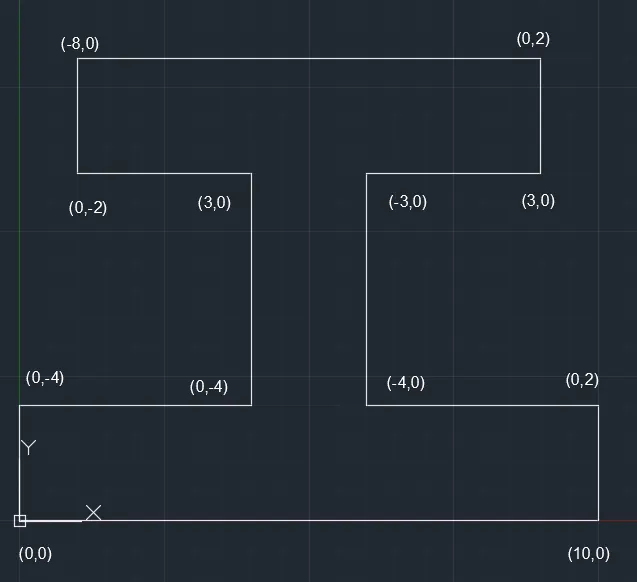
P-8
Aim ,
* First set the point as (0,0) using line command
* Then using @ symbol at first mention every points
* Then (10,0) , (0,2) , (-4,0) , (0,4) , (3,0) , (0,4) , (3,0 ).
* Continue the procedure by (0,2) , (-8,0) , (0,-2) , (3,0) , (0,-4) again(0,-4).
* Then close it.
Diagram,
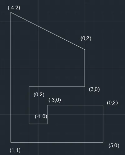
P-9
Aim ,
To draw a given diagram using any co ordinate methods
Procedure ,
*First set the points as (1,1) .
*Then using polar co ordinate method mark other points.
*Using @ at first mark the following coordinates .
*Next points as (5,0) , (0,2) , (-3,0) , (0,-1) , (-1,0) , (0,2) , (3,0) , (0,2 ) , (-4,2).
*Then close it.
Diagram ,
P-10
Aim ,
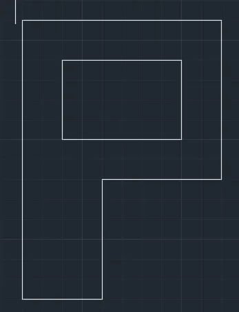
To draw the given p diagram using any co ordinate method.
Procedure ,
* First set the points (1,1) using the line command.
* Then using @ as first to mark the all points.
* (2,0) , (0,3) , (2,0) , (0,4) , (-5,0) and close it . Finish the outer "p"
* Then set starting point as (2,3) and connect inner square using following coordinates.
* (3,0) , (0,2) , (-3,0).
* Finish the inner square.
Diagram ,
Civil Related Problems
Aim ,
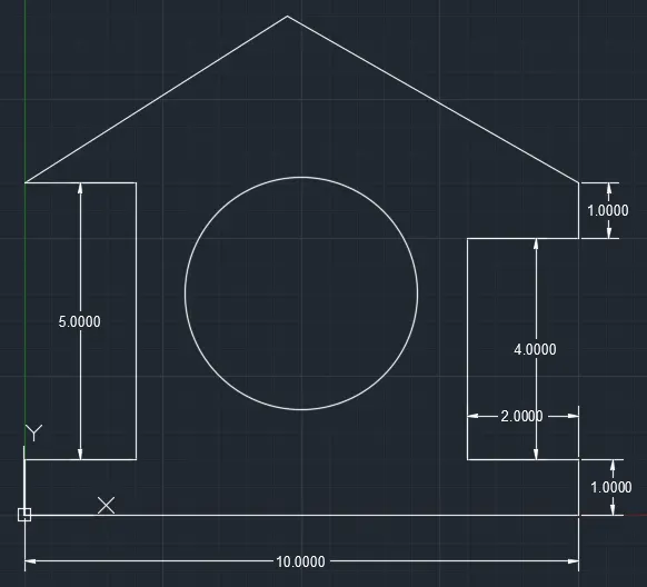
Draw the profile and the trusses using any coordinate system methods.
Procedure ,
* First set the points as (0,0) using line command.
* Then construct the truss by given measurements.
* After finishing the outer section then set a point as (5,4) for the circle.
* construct the circle using radius 2.1
* Then measure everything using dimstyle option.
Diagram ,
Aim ,
Draw the profile and the trusses using any coordinate system methods.
Procedure ,
* First set the points as (1,1)
* Then draw the tuss using line command .
* Mark the given measurements using dimlinear.
Diagram ,