Creating various 3D Models like Furniture, Footing, Girder, Column drop with panel and Gable Wall in AutoCad
Challenge 12 – Creating various 3D Models like furniture, Footing, Girder, Column drop with panel and Gable wall in AutoCAD.
Aim- Creating the various 3D models as given with the help of AutoCAD Software.
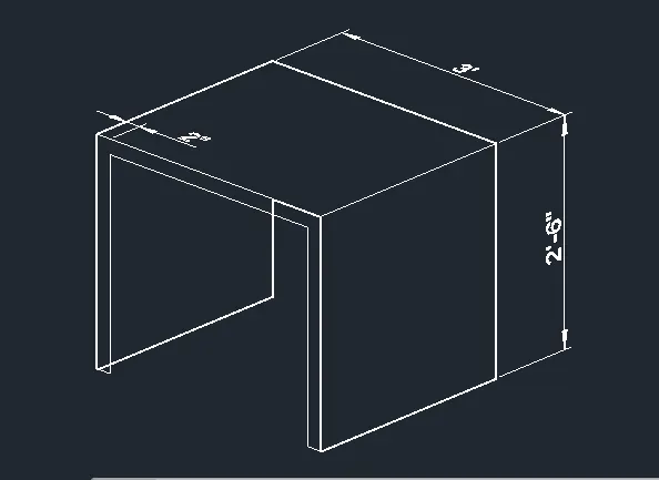
- Furniture
Procedure-
- Open the AutoCAD software and go to the 3D modelling space for creating the geometry
- Set the units to imperial units which will show feet and inches
- Type the Command UNITS and set the units to engineering units.
- Type the Command DIMSTYLE and set the primary units to engineering and precision to 0’00”
- Now type the LINE command and give 2’6” units in +z direction
- Again give the 3’ units in -x direction.
- Again give the 2’6” units in -z direction.
- Again give the 2” units in +x direction.
- Again give the 2’4” units in +z direction.
- Again give the 2’8” units in +x direction.
- Again give the 2’4” units in -z direction.
- Again give the 2” units in -x direction.
- Now type the Command EXTRUDE and select the outer boundary line having the height of 2’6”.
- Now extrude this boundary by 2’6” in +y direction.
- Now type the command 3DFACE and select the planes which we want to hide.
- Now type the Command HIDE and select the 3D faces and click enter.
- Entire drawing is shown as a 3D Geometry.
- Type the Command UCS and take the UCS to the plane, where we have to do the dimensioning.
- Select the axis as per the planes on which we have to do the dimensioning.
- Do the dimensioning and go to the SHADED option.
RESULT:Geometry is drawn as 3D figure.
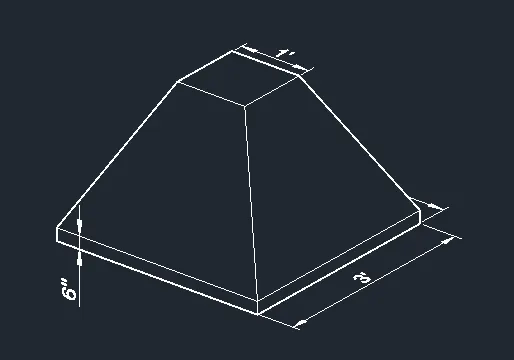
- Isolated footing
Procedure:
- Open the AutoCAD software and go to the 3D modelling space for creating the geometry
- Set the units to imperial units which will show feet and inches
- Type the Command UNITS and set the units to engineering units.
- Type the Command DIMSTYLE and set the primary units to engineering and precision to 0’00”
- Go to the 2-D wireframe.
- Type the Command REC and make a Rectangle of 3’x3’
- Now give the offset of 1’ in the inner of rectangle.
- Rectangle of 1’x1’ is made.
- Now come to the 3D Space.
- Now type the Command MOVE and click the base point as the centre of smaller rectangle
- Now move the smaller rectangle by 2 units in +z direction.
- Type the command extrude and extrude the bigger lower rectangle by 6” in +z direction.
- Join the lines from the smaller rectangle to lower box rectangle.
- Now type the command 3DFACE and select the planes which we want to hide.
- Now type the Command HIDE and select the 3D faces and click enter.
- Entire drawing is shown as a 3D Geometry.
- Type the Command UCS and take the UCS to the plane, where we have to do the dimensioning.
- Select the axis as per the planes on which we have to do the dimensioning.
- Do the dimensioning and go to the SHADED option.
RESULT:Geometry is drawn as 3D figure.
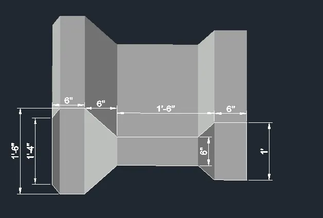
- AASTHO TYPE GIRDER
Procedure:
- Open the AutoCAD software and go to the 3D modelling space for creating the geometry
- Set the units to imperial units which will show feet and inches
- Type the Command UNITS and set the units to engineering units.
- Type the Command DIMSTYLE and set the primary units to engineering and precision to 0’00”
- Now go to the 2-D wireframe
- Type the command LINE and give 1’ units in +y direction.
- Now from the upper point give 6” units in –x direction.
- Now do same at lower point by giving 6” units in same direction
- Now from the centre of the vertical line make a line of 3” in both the sides and join the line as a single line using the JOIN Command.
- Now move this line to 9” units in –x direction by using MOVE command and keeping orthogonal mode on
- Join the 6” horizontal line to this line.
- Now from 6” vertical line give the 1’3” in –x direction.
- Now from the 1’ vertical line, copy this line and move it to 2’6” in –x direction keeping orthogonal mode on.
- Extend this copied line by 3”from both the sides to make a 1’6” and join it by using the JOIN command.
- From this line give the offset of 6” in +x direction.
- Join the 1’3” lines to this line.
- Now from this last made 1’6” line give 6” units in –x direction from both the points.
- Now extend these lines to further distance.
- Now from the centre lower 1’6” line make a line 7” to both side and JOIN it to make 1’4” line.
- Now from this draw inclined lines cutting the 1’6” extended lines at the required desired angle as shown in the geometry.
- Now extrude the whole figure to the certain distance.
- Now type the command 3DFACE and select the planes which we want to hide.
- Now type the Command HIDE and select the 3D faces and click enter.
- Entire drawing is shown as a 3D Geometry.
- Type the Command UCS and take the UCS to the plane, where we have to do the dimensioning.
- Select the axis as per the planes on which we have to do the dimensioning.
- Do the dimensioning and go to the SHADED option.
RESULT: Geometry is drawn as 3D figure.
- Drop Column with Panel
Procedure:
- Open the AutoCAD software and go to the 3D modelling space for creating the geometry
- Set the units to imperial units which will show feet and inches
- Type the Command UNITS and set the units to engineering units.
- Type the Command DIMSTYLE and set the primary units to engineering and precision to 0’00”
- Now go to the 2-D wireframe
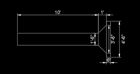
- Type the Command Rec and give the dimension as 4’6”x4’6”
- Now from the centre of the rectangle line give the offset of 6”.
- Rectangle of 3’6”x3’6” is drawn.
- Now from this rectangle line give the offset of 10” in the inner side.
- Rectangle of 1’6”x1’6” is drawn.
- Now come to the 3d view.
- Now move the second rectangle to 6” in +z direction.
- Now move the 3rd rectangle to 1’ in +z direction.
- Now from the lower rectangle (4’6”x4’6”) extrude it to 6” in +z direction.
- Join the 2nd and 3rd smaller rectangle from the edges.
- Type the command 3D face and select the planes join by 2nd and 3rd
- Use the Hide command and the hide the faces.
- From the centre of smaller rectangle draw a circle of 8” radius touching the smaller rectangle edges.
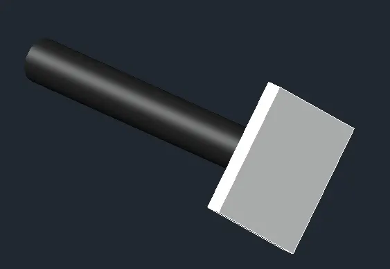
- Now extrude the circle to the 10’ units –x direction in the 3d view.
- Use the Command SOLID EDIT.
- Select the face option and then select the colour option.
- Give the colour to the required geometry.
- Do the dimensioning with the help of UCS command.
- Use the DIMLINEAR Command for dimensioning.
RESULT: Required geometry is made as per given.
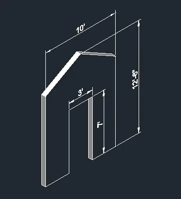
- Gable Wall
Procedure:
- Open the AutoCAD software and go to the 3D modelling space for creating the geometry
- Set the units to imperial units which will show feet and inches
- Type the Command UNITS and set the units to engineering units.
- Type the Command DIMSTYLE and set the primary units to engineering and precision to 0’00”
- Type the command line and give 3’ in +y direction.
- Again give the 7’ units in the +z direction.
- Again give the 3’ units in the +x direction.
- Again give the 7' units in the -z direction.
- Again give the 4’ units in the +y direction.
- Again give the 12’6” units in the +z direction.
- Again give the 12’6” units in the +z direction from the starting point.
- Again give the 7’7” units in the +z direction from the centre of 3’ line.
- Again give the 0.5’ units from the last line in the +x direction for top thickness.
- Giving the side thickness
- Again give the 1’ units in the -x direction from the top point of 12’6” line
- Again give the 12’6” units in the -z direction.
- Again give the 1’ unit in +x direction.
- Now type the command 3DFACE and select the planes which we want to hide.
- Now type the Command HIDE and select the 3D faces and click enter.
- Entire drawing is shown as a 3D Geometry.
- Type the Command UCS and take the UCS to the plane, where we have to do the dimensioning.
- Select the axis as per the planes on which we have to do the dimensioning.
- Do the dimensioning and go to the SHADED option.
RESULT: Geometry is drawn as 3D figure.