Creating various 3D Models like Furniture, Footing, Girder, Column drop with panel and Gable Wall in AutoCad
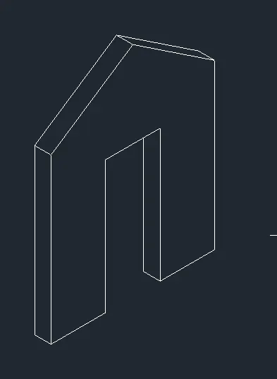
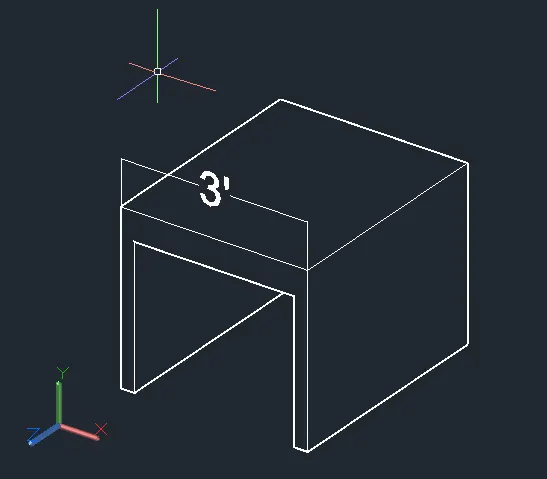
Q 1). Create a 3D Furniture element as shown in the Figure. Assume dimensions Which are missing.
Aim:- To create a 3D Furniture element as shown in the Figure.
Procedure:-
- open a new AutoCAD file> 3D Modeling.
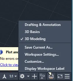
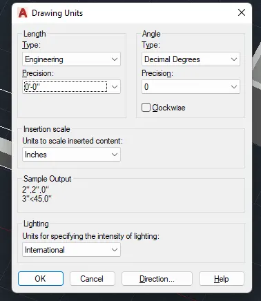
- let's change the units for that on the command prompt type units>engineering>inches>0"-0".
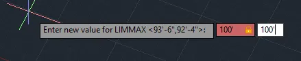
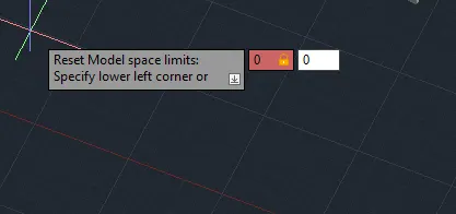
- set the limits, on command prompt type 'Limax' > 100',100'
- on the command prompt type 'Limits' > 0,0
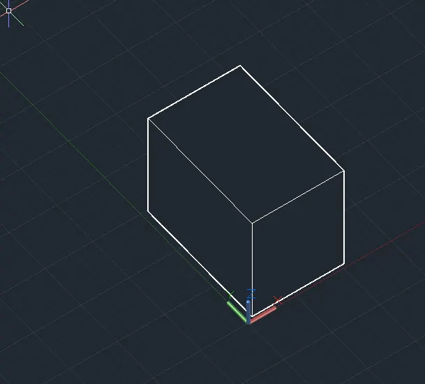
- now, by using the L command give the lines of dimensions 2',3' & 2;-6".
- after that extrude the rectangle by using Extrude command.
- now draw the inner rectangle by using the 'rec' command.
- To subtract the inner object use the subtract command.
Result:-
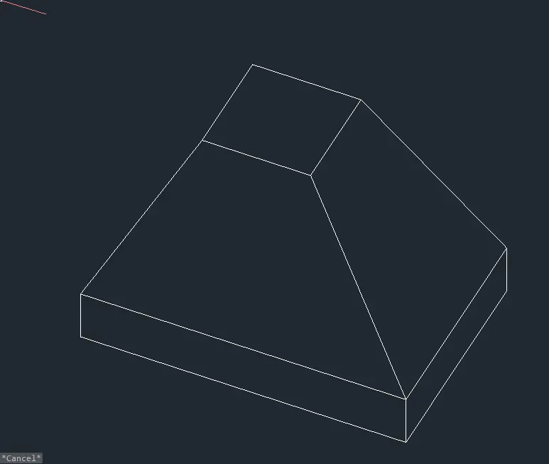
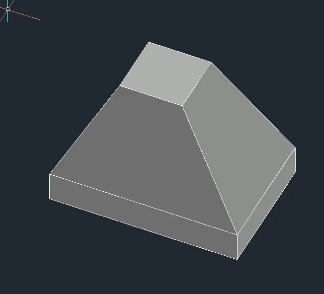
Q 2). Create the 3d Model of an Isolated footing as shown in Figure.
Aim:- To Create the 3D model of an Isolated footing.
Procedure:-
- open a new AutoCAD file> 3D Modeling
- let's change the units for that on the command prompt type units>engineering>inches>0"-0".
- set the limits, on the command prompt type 'Limax' > 100',100'
- on the command prompt type 'Limits' > 0,0
- by using the line command draw desired lines of dimensions 6",3',2'
- draw a rectangle of size 1' x 1'.
- by using the 3Dface command to give the surface.
Result:-
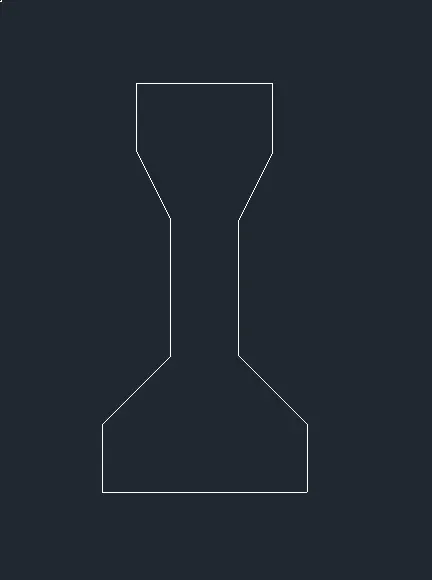
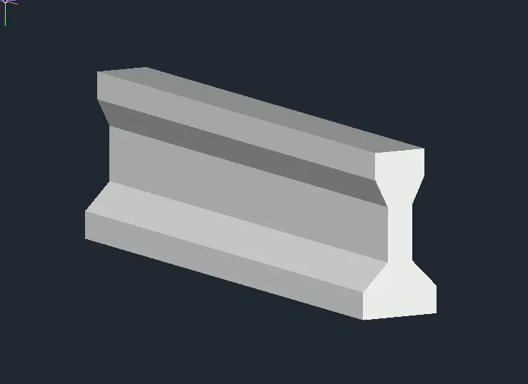
Q 3). Create the 3D view of the AASTHO Type Girder.
Aim:- To create the 3D view of the AASTHO-type girder in AUTOCAD 3D.
Procedure:-
- open a new AutoCAD file> 3D Modeling
- let's change the units for that on the command prompt type units>engineering>inches>0"-0".
- set the limits, on the command prompt type 'Limax' > 100',100'
- on the command prompt type 'Limits' > 0,0
- by using the L command to draw the desired lines at the SW view.
- again using the line command draw the line of distance 1'-6",6", 1'-6" and 1"
- now, extrude the object by using extrude command.
Result:-
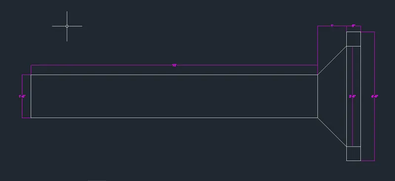
Q 4). Create a 3d Model of a drop column with the panel as shown in the section and isometric view.
Aim:- To create a 3D model of a drop column with the panel.
Procedure:-
- open a new AutoCAD file> 3D Modeling
- let's change the units for that on the command prompt type units>engineering>inches>0"-0".
- set the limits, on the command prompt type 'Limax' > 100',100'
- on the command prompt type 'Limits' > 0,0.
- by line command draw the desired lines of distance 10', 1'-6",6",3'-6",4'-6".
- draw a circle by using command C.
- extrude the object by using extrude command.
- with 3dorbit the 3D view is obtained.
Result:-
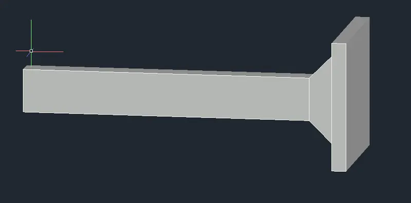
Q 5). Create the 3d model of a wall as shown in Figure. Consider wall thickness as 9”.
Aim:- To create the 3d model of a wall using Autocad.
Procedure:-
- open a new AutoCAD file> 3D Modeling
- let's change the units for that on the command prompt type units>engineering>inches>0"-0".
- set the limits, on the command prompt type 'Limax' > 100',100'
- on the command prompt type 'Limits' > 0,0.
- open drafting settings (ds) off "snap on" and off "grid on".
- select on isometric snap & turn on ortho mode (f8).
- in the command prompt type line
- specify the point or select a point
- press f5 for isodraft to get the line in desired diection, keeping the isodraft in left direction one side of the wall is drawn.
- changing the isodraft in the other direction thr next side of the wall is drawn.
- in the command prompt type the required distance.
Result:-