Creating a Floor plan, Footing detail and Isometric view using AutoCad
Challenge - 2
Q.5)
Procedure:-
Commands used in this challenge are
- Line 'L'
- Copy 'CO' or 'CP'
- PolyLine 'PL'
- Trim 'TR'
- Offset 'O'
- Isometric View
- Text
- Dimension 'DIM'
- Dimstyle 'D'
- MATCHPROP 'MA'
- Move 'M'
- Mirror 'MI'
- Fillet 'F'
- Erase 'E'
Q.1) Draw C-1 (C.S. OF LOAD BEARING WALL OVER SPREAD FOOTING )
Introduction:- This kind of foundation is used to support walls. This footing takes load from the walls of the structure and transfers the loads to the ground soil.
Procedure:-
- line command
- starting point 'a' ( 0, 0 )
- from 'a' 0.45 unit left till 'b'
- after that move 0.25 units to 'c'
- then 0.20 unit right at 'd'
- continue the line 0.40 unit up at 'e'
- 0.05 unit right 'f'
- 0.25 unit up at 'g'
- 0.15 unit up at 'h'
- 0.05 unit right at 'i'
- 0.60 unit up at 'j'
- 0.05 unit up at 'k'
- 1.0 unit up at 'l'
- 0.15 unit on right at 'm'
- esc
- select the entire line from point 'a' to 'm'
- (now by using mirror command ) 'MI' command, from 'm' and do 'no'
- esc
- line command, draw lines KM, JO, DP, IP
- esc
- line command
- again start from 'g'
- 1.15 unit in left side at 'w'
- then start drawing stair rise and run of 0.15 & 0.3 units till point 'y'
- esc
Result:- 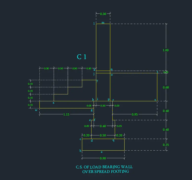
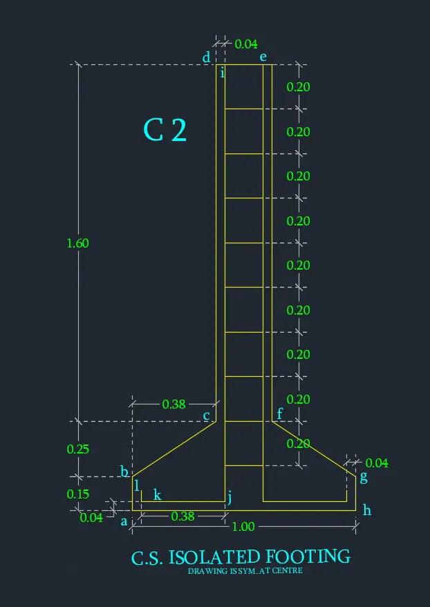
Q.2)
AIM:- Draw C-2 (C.S. ISOLATED FOOTING )
Introduction:- They are independent footing designed to support a single column. this footing has been used when columns are spaced in vast distances. For good Soil bearing capacity, this is used. Depending on the X-section of the column isolated footing shapes are square, rectangle, circular, etc.
Procedure:-
- line command
- starting point 'a' ( 0, 0 )
- b = 0, 0.15
- c = 0.38, 0.40
- d = 0.38, 2.0
- i = 0.42, 2
- j = 0.42, 0.04
- k = 0.04, 0.04
- l = 0.04, 0.09
- esc
- line command
- from 'i' 0.17 unit right at 'e'
- esc
- now select line IE
- by using the 'copy' command, copy line IE. select base point as 'i', scroll the cruser in downward and put the interval 0.20 unit and copy line IE nine-time
- esc
- now select line from a to I, by using mirror command mirror from a to i , to get e to h lines
- esc
- line command
- join a to h
- esc
Result:-
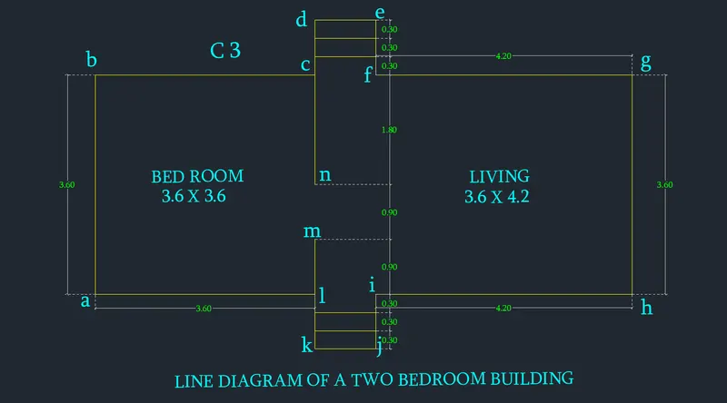
Q.3)
AIM:- Draw C-3 (C.S. Line diagram of a two-bedroom building )
Introduction: Line drawings are drawing with details of dimensions and components of the building. The two-bedroom building consists of a 1-Living room, 1-bedroom, and stairs in both directions.
Procedure:-
- new file
- line command
- starting point is 'a' ( 0, 0)
- b = 0, 3.60
- c = 3.60, 3.6
- d = 3.60, 4.50
- e = 4.60, 4.50
- f = 4.60, 3.60
- g = 8.80, 3.60
- h = 8.80, 0.0
- esc
- now, by using offset command 'O'. offset the line DE in downward direction at distance of 0.30.
- esc
- Select the entire portion from 'b' to 'g' and by using 'MI' command mirror it at point 'h' to 'a'
- esc
- line command
- from 'c' to 'n' 1.80 in downward
- from 'l' to 'm' 0.90 in upward
- esc
- by using 'DIM' command, given the dimension of all lines
- ecs
Result:-
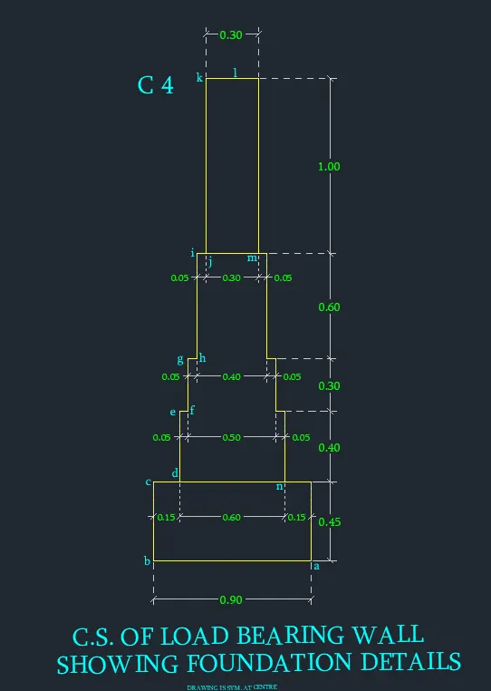
Q.4)
AIM:- To Draw C-4 (C.S. load-bearing wall showing foundation details )
Introduction: This type of foundation or load-bearing wall is a wall that takes loads from the columns, the beam, & the slab. And it used to transfer loads coming from those to the ground below.
Procedure:-
- open autocad
- new file
- 'rec' command
- draw a rectangular from point 'a' of length 0.9 & width 0.45
- ESC
- line command
- now start to draw a line from point 'd' to point 'l' as per the given dimension
- ESC
- now select the line from 'd' to 'l'. 'MI' command & mirror it at point 'l'
- esc
- line command
- join 'd' & 'n'
- enter
- join 'j' & 'm'
- esc
- 'DIM' given the dimension of every line
- esc
Result:-
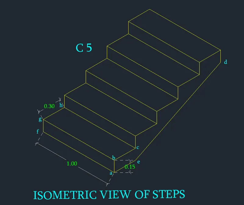
Q.5)
AIM:- To Draw C-5 Isometric view of staps
Introduction: Stairs are the important component of the building which used to join different floors at different heights. stairs have two components, one is vertical called rise & another is a horizontal called thread or run.
Procedure:-
- open a new file using the 'NEW' command
- turn on isometric view through the grid and snap settings
- use F5 to change the direction of the isometric view
- F8 to turn on orthomode
- 'rec' command, draw a rectangle 'abgf' of length 1.00 & width 0.15 in isometric view up direction
- esc
- 'L' enter
- start to draw line from 'b' and create run & rise of 0.03 & 0.15 in right and up direction till 'd'
- after that close it at 'a' through 'e'
- esc
- now by using the copy command copy the right side of the stair line to the left side
- esc
- ERASE the unrequired line through 'e' command
- esc
- 'L' enter, join point 'h' & 'c'. Like that join all other also
- esc
Result:-
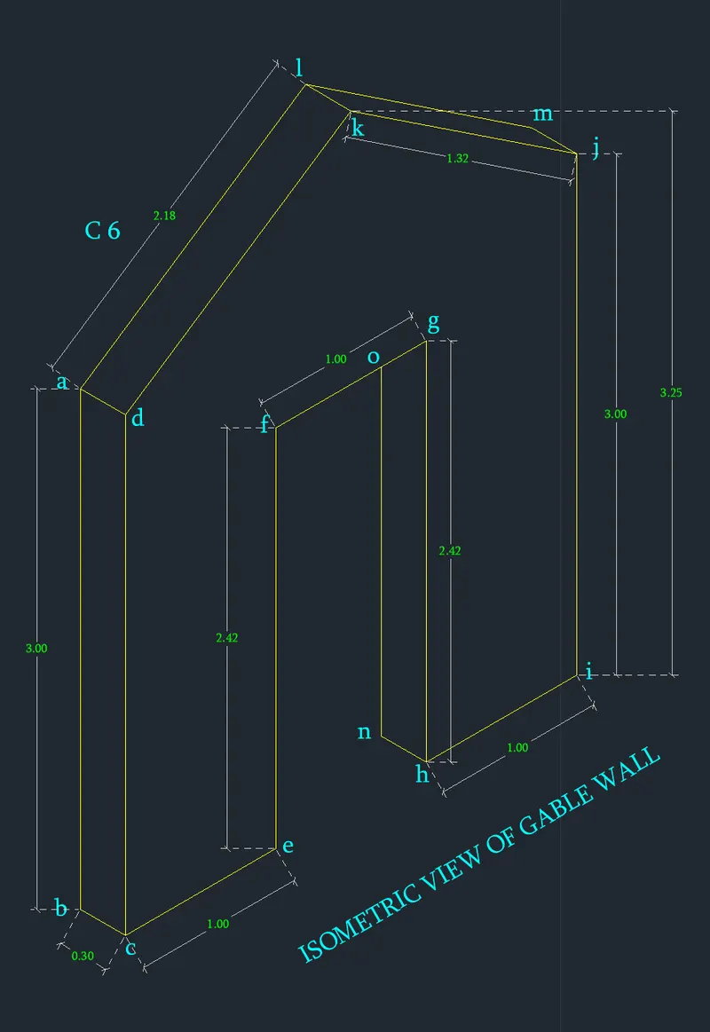
Q.6)
AIM:- To Draw C-6 Isometric view of Gable wall
Introduction: A wall with triangular portion between the intersecting edge of roof pitches is called Gable wall.
Procedure:-
- open a new file using the 'NEW' command
- turn on isometric view through the grid and snap settings
- use F5 to change the direction of the isometric view
- F8 to turn on orthomode
- 'rec' command draws a rectangle 'abcd' of 3.0 and 0.3 in upward firection from 'b'
- esc
- 'L' enter, start drawing line from 'c' to 'j' as per given dimension
- esc
- find the point 'k' and loin DK & KJ
- select dkj line copy it and to point 'a'
- after that join LK
- esc
Result:-