Creating various 3D Models like Furniture, Footing, Girder, Column drop with panel and Gable Wall in AutoCad
1):
Aim: To create a 3D Furniture element
Introduction: To create a 3D Furniture element. By using AutoCad
Procedure:
Step1:
- Frist change the autocad work space to the 3d modeling
- Now set the units and limit and zoom all z enter and A enter
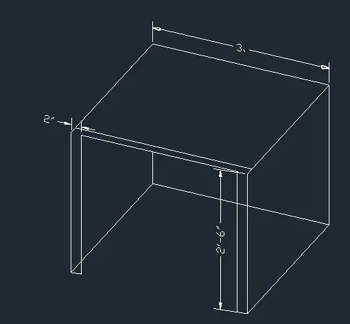
- Take a line command and draw a line in vertical in y axis with length of 2’6”
- Next continue to line command draw another line in x-y plan unit of 3’ continue the line command draw a rectangle
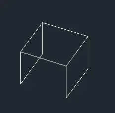
Stpe2:
- Now take the offset command and give the offset unit as 2” select the line for offset and give the offset direction
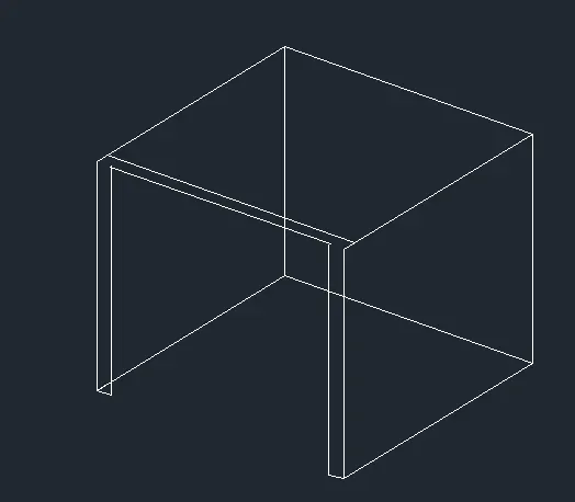
Step3:
- To provided the dimensions
- From the ribbon select the visualize select the ucs manages set the ucs coordinate at the edge of the object x axis and y and z axis
- Now take the command DIMLIN select the first point and second point and give the dimension position.
Result:
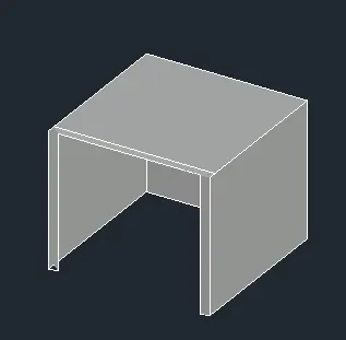
2):
Aim: To Create the 3d Model of an Isolated footing
Introduction: To Create the 3d Model of an Isolated footing. By using Autocad
Procedure:
Step1:
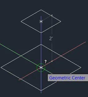
- Take a rec command and draw a rectangle of 2’
- Continue to rec command and draw a rectangle of 1’
- Place a rectangle of 1’ center of 2’ rectangle

Step2:
- Now take the move command and select the rectangle and move inn the z- axis with distance of 2’
Step3:
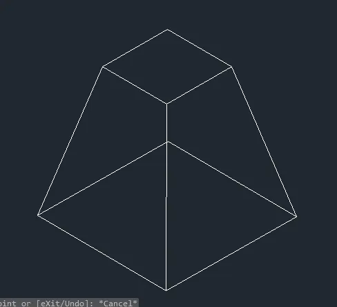
- Now take the line command and select the edge point of above rectangle and join the line to edge point of below rectangle as shown.
Step4:
- Now from the ribbon select the extrude option and select the object as bottom rectangle and give the value of 6”
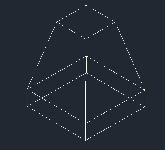
Result:
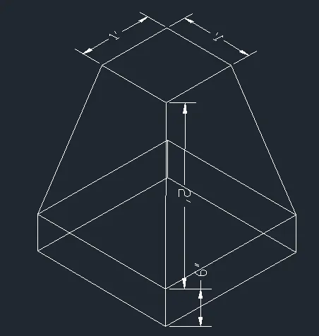
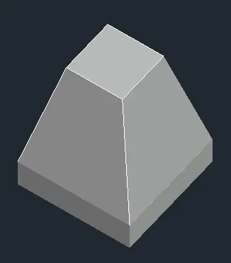
3):
Aim: To create the 3D view of the AASTHO Type Girder
Introduction: To create the 3D view of the AASTHO Type Girder. By using AutoCad
Procedure:
Step1:
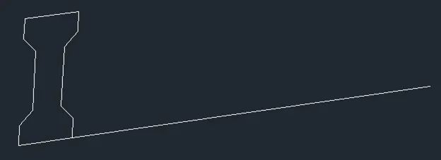
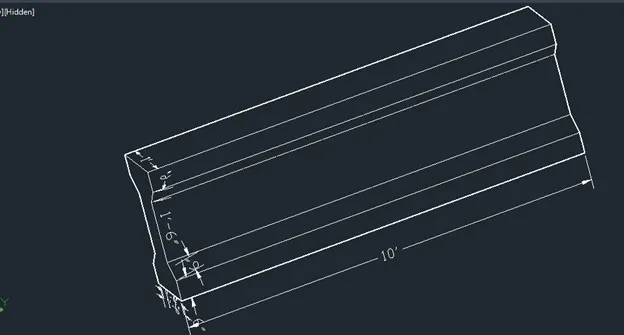
- Take a command line and a draw a line of 1’6” in x -axis and vertical line in y- axis 6” next draw a inclined line at 45 degree with length of 6”
- Now take the mi command and mirror it on other side
- Next take the line command and draw a line of 1’6” vertical in y-axis next draw a inclined line at 45 degree with length of 6”
- Continue to line command and draw a line of 1’ in x axis and join the remain part with above value of the lines
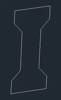
Step2:
- Now take the line command a draw a line of 10’ in Z- axis as shown
Step3:
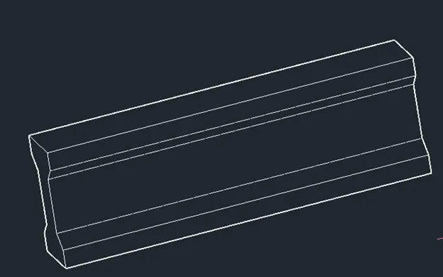
- Now take the “sweep” command
- Select the object to sweep enter and select the line
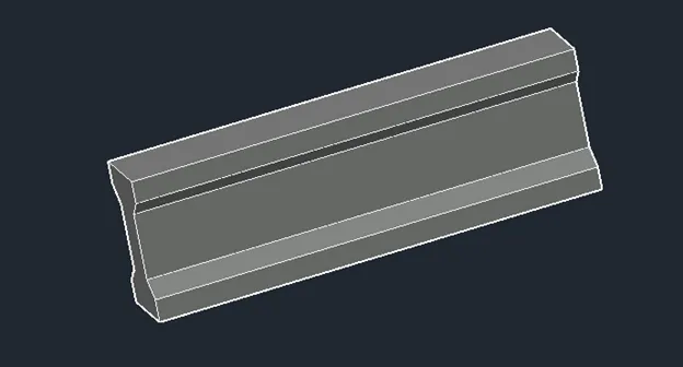
- From the visual style select the shade of grey option to view the object in solid frame
Result:
4):
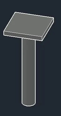
Aim: To create a 3d Model of a drop column with panel
Introduction: To create a 3d Model of a drop column with panel. By using Autocad
Procedure:
Step1:
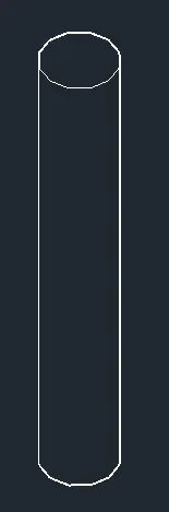
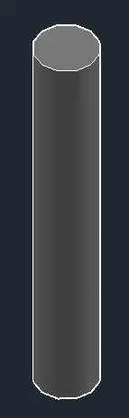
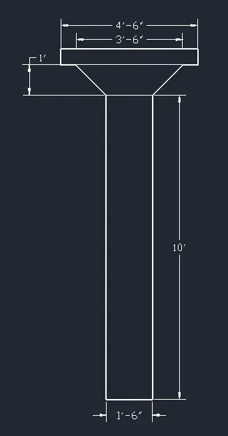
- Take a command circle and draw a circle with dia of 1’6”
- Next take from the ribbon select the extrude and give the height as 10’
Step2:
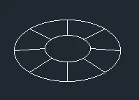
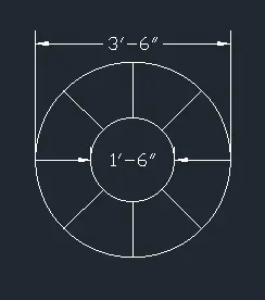
- Now from the toolbar take the cone with the base dia of 1’6” and top dia 3’6” and height is 1”
Step4:
- Now from the ribbon select the extrude option and give the height of 6”
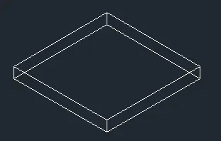
- Take a rec command and draw a rectangle of 4’6” and place it at the center of the circle
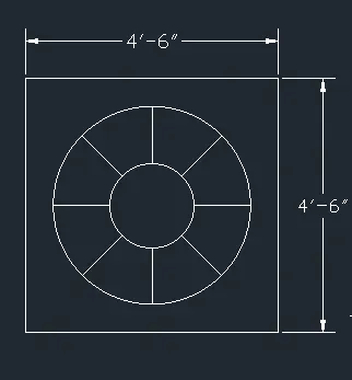
Step5:
- now take the isometric view from the view cube
- next from the visual style control select the hidden
- next from the toolbar select the solid union option and select the object for assign the property
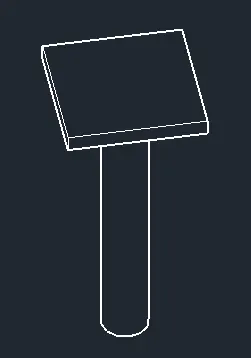
Result:
5):
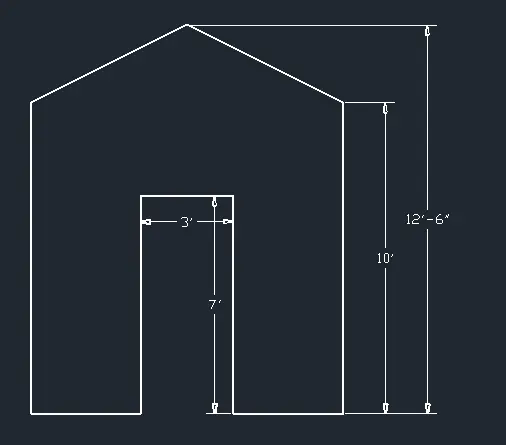
Aim: To create the 3d model of a wall
Introduction: To create the 3d model of a wall. By using AutoCad
Procedure:
Step1:
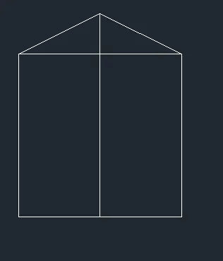
- From the view control set the front view
- Now take the rec command and draw a rectangle od 10’x10’
- Next take the line command draw a line of 12’6” from the mid od rectangle
- From top point of line draw a inclined line edge of both side
Step2:
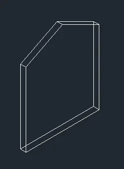
- Now trim the horizontal line and delete vertical line
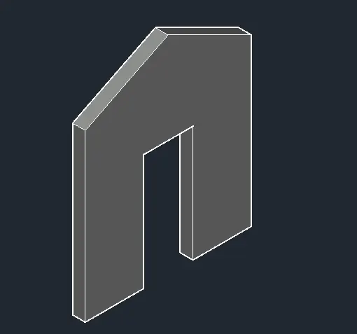
- Go to the isometric view from the view cube
- From the toolbar take “extrude” and give the value as 9”
Step3:
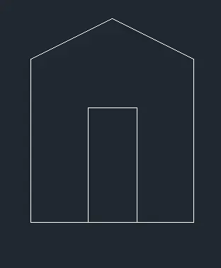
- Now draw another rectangle of 3’x7’
- From the toolbar take “extrude” and give the value as 9”
- Change the view control as front view and place the rectangle in the mid as shown
Step4:
- Go to the isometric view from the view cube
- From the visual style control set the hidden view
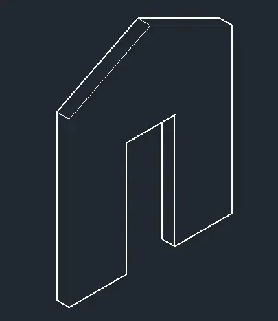
Result: