Creating various 3D Models like Furniture, Footing, Girder, Column drop with panel and Gable Wall in AutoCad
AIM : 1. Creating various 3D Models like Furniture, Footing, Girder, Column drop with panel and Gable Wall in AutoCad
Introduction: In this challenge i have draft the above meationed drawing i.e, Creating various 3D Models like Furniture, Footing, Girder, Column drop with panel and Gable Wall, using AutoCad. here in this challange i have attached all the drawings in a image format and with the proper procedure as possible.
The comman commands which are used in this challange are discussed below,
Selecting of Tools:
- Line: Ribbon< Home< Line, Command: Line or L, Home< Draw< Line.
- Polyline: Ribbon< Home< Polyine, Command: polyline or pl, Home< Draw< polyline.
- Rectangle: Ribbon< Home< rectangle, Command: rectangle or rec, Home< Draw< rectangle.
- Ploygon: Ribbon< Home< Ploygon, Command: Ploygon or pol, Home< Draw< Ploygon.
- Circle: Ribbon< Home< Circle, Command: Circle or C, Home< Draw< Circle.
- Fillet: Ribbon< Home< Fillet, Command: Fillet or F, Home< modify< Fillet.
- Chamfer: Ribbon< Home< Chamfer, Command: Chamfer or cha, Home< modify<Chamfer.
- Move: Ribbon< Home< move, Command: move or M, Home< modify<Move.
- Copy: Ribbon< Home< Copy, Command: Copy or co, Home< modify<Copy.
- TRIM: Ribbon< Home< trim, Command: TRIM or TR, Home< modify
- 3d Fillet: Ribbon< Home< Fillet, Command: Fillet or F, Home< modify< 3d Fillet.
- 3d Chamfer: Ribbon< Home< Chamfer, Command: Chamfer or 3d cha, Home< modify<3d Chamfer.
Question 1:
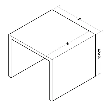
Create a 3D Furniture element as shown in the Figure. Assume dimensions which are missing.
ANS: Here i have attached the image which i have made in autocad 2019,
Procedure:
- Open auto cad 2019 icon change the work space setting as 3D modelling.
- Now change the setting to isometric view or by pressing the home button which is present at the top right corner.
- Go to the custom view and select parallel option.
- In order to create a 3D furniture element select a poly solid option which is present in solid panel.
- Select poly solid set a height of 2’ 6” and width as 2”.
- Now select a point drag in the x direction with a length of 3’ and move in the y direction with a length of 3’.
- Now come back to negative x direction with a length of 3’ press enter.
- This create a gable now draw a rectangle by using REC command at extreme top edges of the3D furniture element
- Now select press pull option which is present in the solid panel and press pull the rectangle in negative z direction with a thickness of 2’ press enter.
- Select union command which is present in the solid panel and select the 3D furniture element along with the rectangle union and press enter.
- This is how a 3D object of gable wall is created.
- In order to provide dimensions in the z direction type UCS press enter select face option now place that UCS in the Z face.
- Select the annotate option and provide the dimension where ever required.
Question 2:
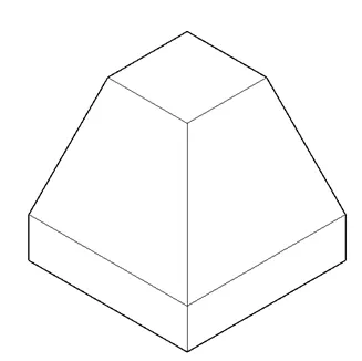
Create the 3d Model of an Isolated footing as shown in Figure.
ANS: Here i have attached the image which i have made in autocad 2019,
Procedure:
- Open auto cad 2019 icon change the work space setting as 3D modelling.
- Now change the setting to isometric view
- Or by pressing the home button which is present at the top right corner.
- Go to the custom view and select parallel option.
- Now in order to create a isolated footing create a rectangle of size 2’*2’.
- Use press pull option present in solid panel press pull the rectangle to 6”
- Now use pyramid option and select a point and give a base radius of 1’
- Select top radius option and give a radius of 6” and set a height of 2’.
- Select the created pyramid and copy at the top of created rectangle press enter.
- Select the union option present in the solid panel.
- Select both rectangle and pyramid and union it.
- This is how an isolated footing is created.
Question 3:
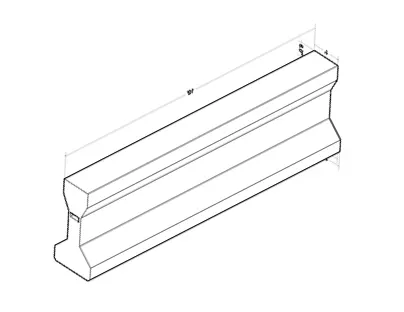
Create the 3D view of the AASTHO Type Girder.
ANS: Here i have attached the image which i have made in autocad 2019,
Procedure:
- Open auto cad 2019 icon change the work space setting as 3D modelling.
- Now change the setting to isometric view or by pressing the home button which is present at the top right corner.
- Go to the custom view and select parallel option.
- In order to create a AASTHO type girder select a poly solid option which is present in solid panel.
- Select poly solid set a height of 2’ 6” and width as 2”.
- Now select a point drag in the x direction with a length of 3’ and move in the y direction with a length of 3’.
- Now come back to negative x direction with a length of 3’ press enter.
- This create a gable now draw a rectangle by using REC command at extreme top edges of the AASTHO type girder.
- Now select press pull option which is present in the solid panel and press pull the rectangle in negative z direction
- with a thickness of 2’ press enter.
- Select union command which is present in the solid panel and select the AASTHO type girder along with the rectangle union
- and press enter.
- This is how a 3D object of gable wall is created.
- In order to provide dimensions in the z direction type UCS press enter select face option now place that UCS in the Z face.
- Select the annotate option and provide the dimension where ever required.
Question 4:
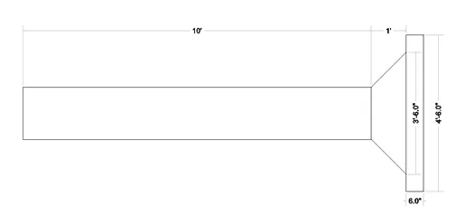
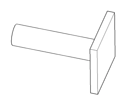
Create a 3d Model of a drop column with panel as shown in section and isometric view
ANS: Here i have attached the image which i have made in autocad 2019,
Procedure:
- Open auto cad 2019 icon change the work space setting as 3D modelling.
- Now change the setting to isometric view
- Or by pressing the home button which is present at the top right corner.
- Go to the custom view and select parallel option.
- Now in order to create a Drop column with panel create a rectangle of size 2’*2’.
- Use press pull option present in solid panel press pull the rectangle to 6”
- Now use pyramid option and select a point and give a base radius of 1’
- Select top radius option and give a radius of 6” and set a height of 2’.
- Select the created pyramid and copy at the top of created rectangle press enter.
- Select the union option present in the solid panel.
- Select both rectangle and pyramid and union it.
- This is how an Drop column with panel is created.
Procedure:
- Open auto cad 2019 icon change the work space setting as 3D modelling.
- Now change the setting to isometric view
- Or by pressing the home button which is present at the top right corner.
- Go to the custom view and select parallel option.
- Now in order to create a Drop column with panel create a rectangle of size 2’*2’.
- Use press pull option present in solid panel press pull the rectangle to 6”
- Now use pyramid option and select a point and give a base radius of 1’
- Select top radius option and give a radius of 6” and set a height of 2’.
- Select the created pyramid and copy at the top of created rectangle press enter.
- Select the union option present in the solid panel.
- Select both rectangle and pyramid and union it.
- This is how an Drop column with panel is created.
Question 5:
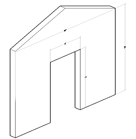
Create the 3d model of a wall as shown in Figure. Consider wall thickness as 9”.
ANS: Here i have attached the image which i have made in autocad 2019,
Procedure:
- Open auto cad 2019 icon change the work space setting as 3D modelling.
- Now change the setting to isometric view or by pressing the home button which is present at the top right corner.
- Go to the custom view and select parallel option.
- In order to create a gable wall select a poly solid option which is present in solid panel.
- Select poly solid set a height of 2’ 6” and width as 2”.
- Now select a point drag in the x direction with a length of 3’ and move in the y direction with a length of 3’.
- Now come back to negative x direction with a length of 3’ press enter.
- This create a gable now draw a rectangle by using REC command at extreme top edges of the gable wall.
- Now select press pull option which is present in the solid panel and press pull the rectangle in negative z direction
- with a thickness of 2’ press enter.
- Select union command which is present in the solid panel and select the gable wall along with the rectangle union and press enter.
- This is how a 3D object of gable wall is created.
- In order to provide dimensions in the z direction type UCS press enter select face option now place that UCS in the Z face.
- Select the annotate option and provide the dimension where ever required.