Creating various 3D Models like Furniture, Footing, Girder, Column drop with panel and Gable Wall in AutoCad
1.
AIM =
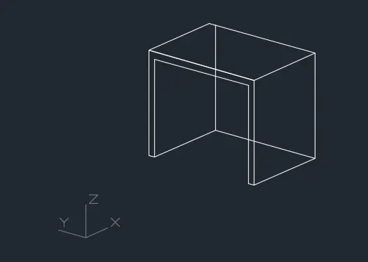
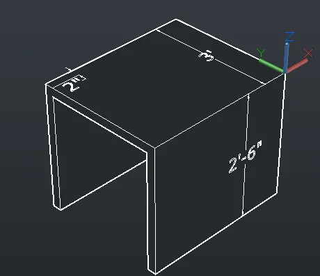
Create a 3D Furniture element as shown in the Figure
Procedure=
- Click on AutoCAD application and open this application
- Type QNEW in command bar and enter
- Select default setting as Imperial
- In default setting click on use a wizard and in that advance setting and set unit as Architectural and precision as 0’0” and press Next
- Set Angle as Decimal Degree and precision as 0 and click next
- Set Angle Measure as EAST and press NEXT
- Set Angle Direction as Counter-Clockwise and press NEXT
- Set Area by providing Length as 50’ and Width as 50’
- Press finish
- Keep ortho, Object snap >ON
- Keep Snap and Grid > Off
- Un+enter
- Type > Architectural, Precision > 0’0”
- Units to scale inserted content > Inches
- Enter
- Select workspace switching > 3D Modelling
- Select Visual style control > 2D Wireframe
- Take 3D Orbit command
- Select view such as the UCS direction is as shown below
- Take line command
- Select first point > Anywhere in the drawing
- Line specify next point > @0,0,2’6” > Enter
- Line specify next point > @0,3’,0> Enter
- Line specify next point > @0,0,-2’6” > Enter
- Line specify next point > @0,-2”,0 > Enter
- Line specify next point > @0,0,2’4” > Enter
- Line specify next point > @0,-2’8”,0 > Enter
- Line specify next point > @0,0,-2’4” > Enter
- Line specify next point > @0,-2”,0 > Enter
- It will shows the following result
- Take a rectangle command
- Specify first corner point > Click on top left corner point
- Click > Dimension
- Specify Length > 2’2”
- Specify width > 3’
- Use line command to connect the rectangle as shown below
- Take 3D face command
- Specify all the four point of the top rectangle
- Enter > Hide > Enter
- Similarly do the 3D face command to all the faces of the drawing
- Click on ANNOTATION tab
- Click on Dimension
- Click > Manage dimension style
- New
- Style name > 3D
- Set the characteristics of dimensions as
- Select the yellow colour for the dimension style and extension line
- Select arrowhead size as 4”
- Select the text as green colour
- Then select linear dimensions
- Provide the linear dimension
- It will shows the following result
Output =
2.
AIM =
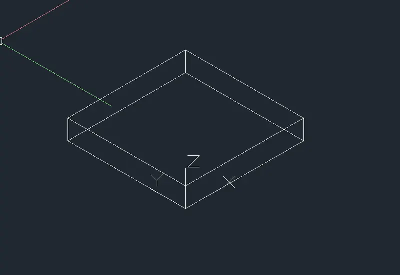
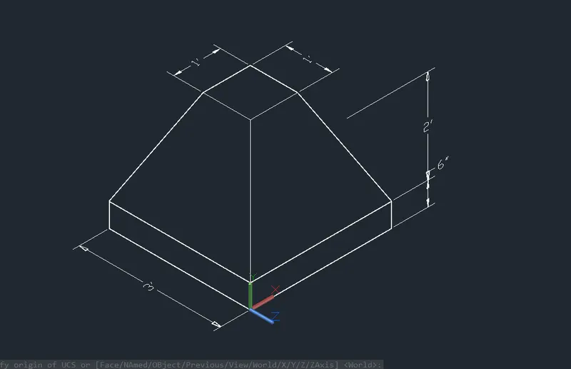
Create the 3d Model of an Isolated footing as shown in Figure.
Procedure =
- Click on AutoCAD application and open this application
- Type QNEW in command bar and enter
- Select default setting as Imperial
- In default setting click on use a wizard and in that advance setting and set unit as Architectural and precision as 0’0” and press Next
- Set Angle as Decimal Degree and precision as 0 and click next
- Set Angle Measure as EAST and press NEXT
- Set Angle Direction as Counter-Clockwise and press NEXT
- Set Area by providing Length as 5’ and Width as 5’
- Press finish
- Keep ortho, Object snap >ON
- Keep Snap and Grid > Off
- Un+enter
- Type > Architectural, Precision > 0’0”
- Units to scale inserted content > Inches
- Enter
- Select workspace switching > 3D Modelling
- Select Visual style control > 2D Wireframe
- Take 3D Orbit command
- Select view such as the UCS direction is as shown below
- Take rectangle command
- Specify corner point anyehere in the drawing
- Click > Dimension
- Specify Length > 3’
- Specify Width > 3’
- Enter
- Take rectangle command
- Specify corner point anyehere in the drawing
- Click > Dimension
- Specify Length > 1’
- Specify Width > 1’
- Enter
- By keeping object snap on
- Keep the small rectangle such as, both rectangle shows the same centre point
- Take move command
- Select object > Click on small rectangle
- Move it in a Z axis at a distance of 2’6”
- Take the line command
- Join all the corners of the both rectangle as shows below
- Take 3D face command
- Specify all the four point of the top rectangle
- Enter > Hide > Enter
- Similarly do the 3D face command to all the faces of the drawing
- Take the extrude command
- Select object > Click on the bottom rectangle
- Specify extrude height > 6”
- Enter
- Change the visual style control > Hidden
- Click on ANNOTATION tab
- Click on Dimension
- Click > Manage dimension style
- New
- Style name > 3D
- Set the characteristics of dimensions as
- Select the yellow colour for the dimension style and extension line
- Select arrowhead size as 4”
- Select the text as cyan colour
- Then select linear dimensions
- Provide the linear dimension
- It will shows the following result
Output =
3.
AIM =
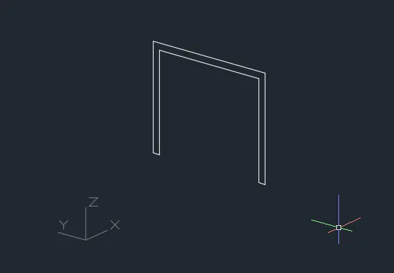
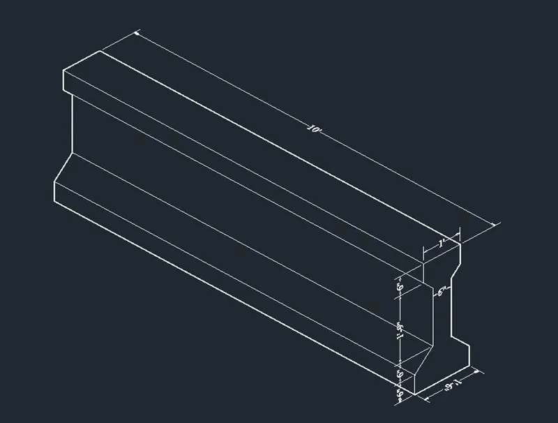
Create the 3D view of the AASTHO Type Girder.
Procedure:
- Type QNEW in command box, press enter, select the imperial as default setting and select ok.
- Type UN in command box, press enter, select the measuring unit engineering with the precision 0’-0”.
- From setting of status bar change setting from drafting and annotation to the 3D modelling.
- Type LIMAX in command box, press enter, specify max limit as 20’,20’ and press enter.
- Type Z in command box, press enter, type A in command box and press enter.
- Select the top view from viewport control.
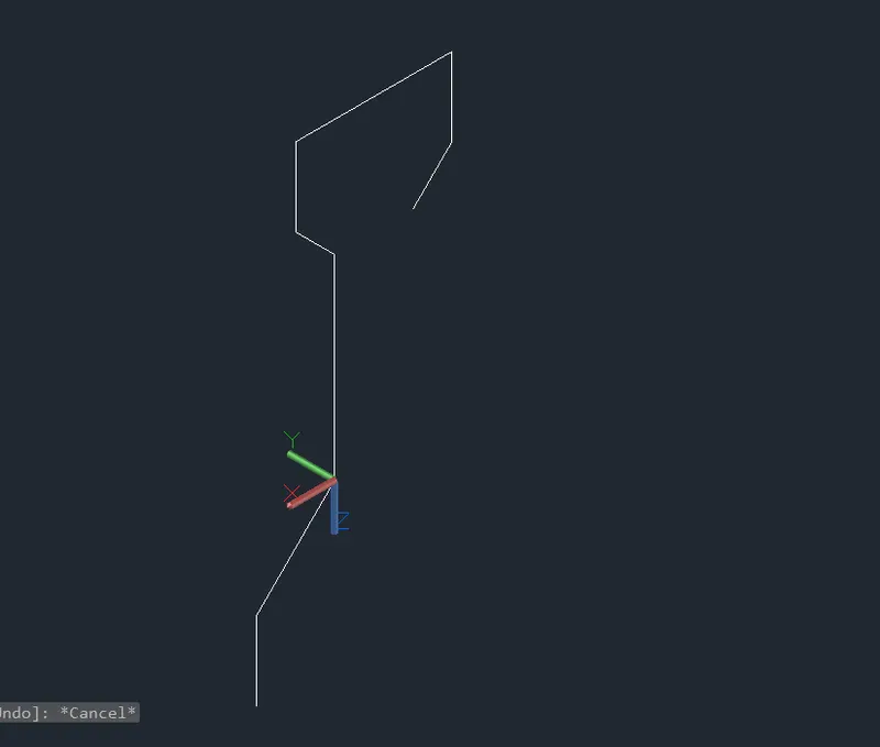
- Type 3P in command box, press enter and specify first point on the screen.
- Specify next point as @9”,0 and press enter.
- Specify next point as @0,6” and press enter.
- Specify next point as @-6”,6” and press enter.
- Specify next point as @0,1’-6” and press enter.
- Specify next point as @3”,3” and press enter.
- Specify next point as @0,6” and press enter.
- And, specify next point as @-6”,0 and press enter.
- Type MIR in command box, select the entire lines, specify first point on mirror line as first endpoint and second point on mirror line as second endpoint on the polyline and mirror it.
- Type JOIN in command box, press enter and select the entire geometry to create it as single object.
- Change the view to custom view from view box.
- Type L in command box, press enter.
- Select the first point and specify next point as @0,-10’, press enter and press escape.
- Type Sweep in command box, press enter, select the drawn object, press enter, select the path to sweep as drawn line of 10’ length.
- Type UCS in command box, press enter.
- Select the face option from command box, select the face on which dimensions are required and press enter.
- Type DIMLIN in command box, press enter and give the dimensions.
- From the viewport control change the custom visual style from 2D wireframe to HIDDEN to get the desired view.
Output =
4.
AIM =
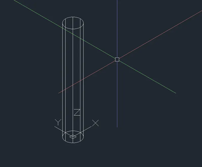
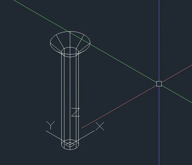
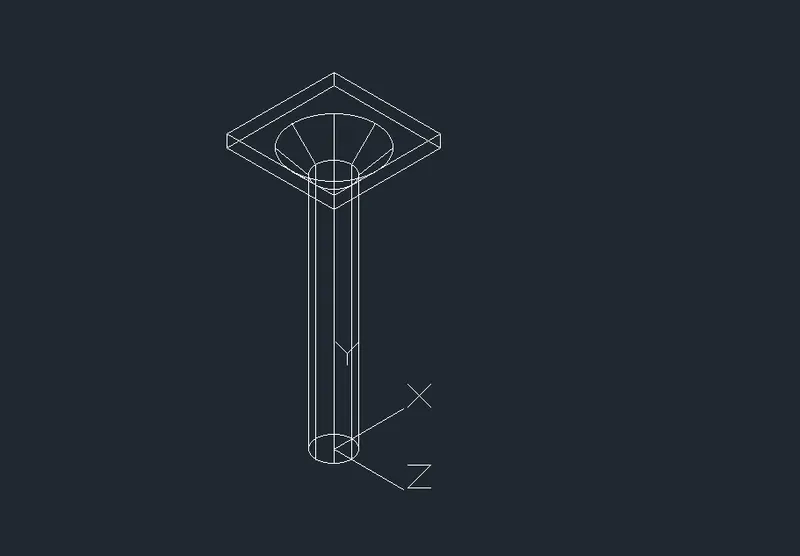
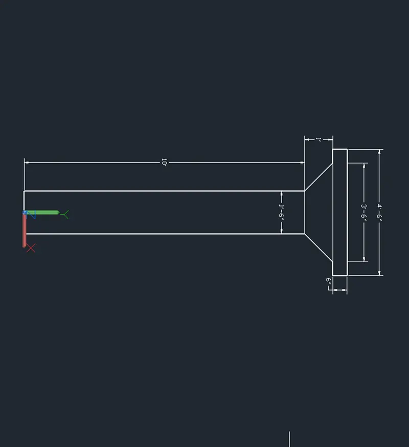
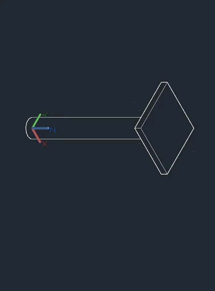
Create a 3d Model of a drop column with panel as shown in section and isometric view.
Procedure =
- Open Autocad software and open new drawing With imperial units.
- Set the units as engineering and precision as 0'-0''
- Switch the work space to 3D modeling and set the view as South-West isometric.
- Create a cylinder.
- Specify the center point of the cylinder as 0,0,0 and radius 9'' at a height of 10'
- Create a cone with specify the center point of the cone at center top of the cylinder.
- Specify the base radius as 9''
- Choose top radius option.
- Specify the to radius as 1'-9'' and specify the height as 1'
- Create rectangle, specify the first corner point at the top center of the cone.
- Specify the other corner point @4'6'',4'6'',0
- Use region command create a surface of the rectangle.
- Extrude the rectangle at a height of 6''
- Change the UCS and check the dimensions by creating dimensions in the model.
- Change to front view.
- Change the UCS select X and specify the rotation angle as 90 deg.
Output =
5.
AIM=
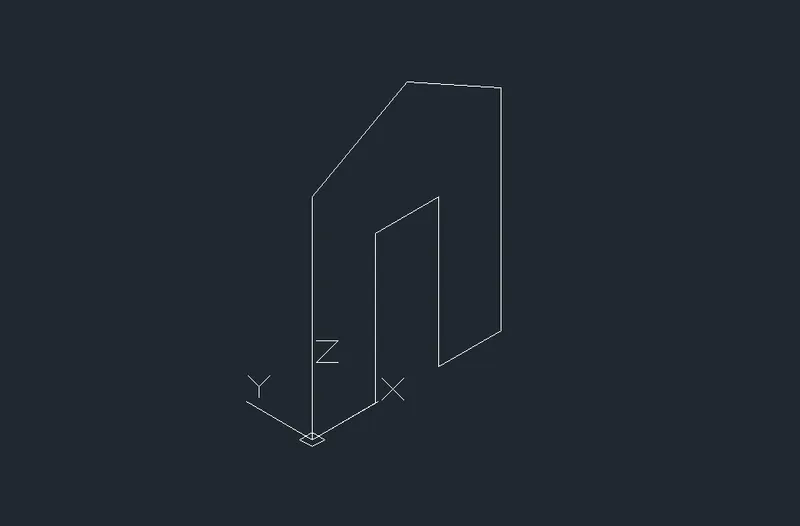
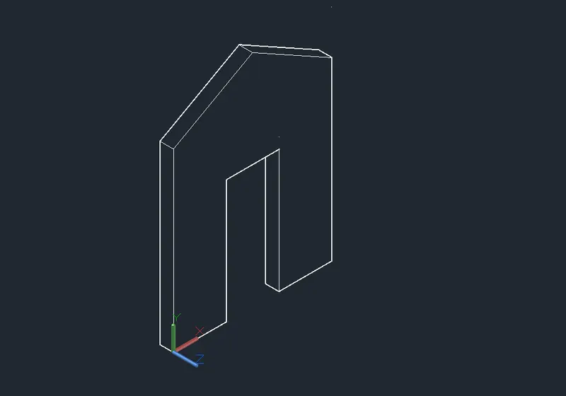
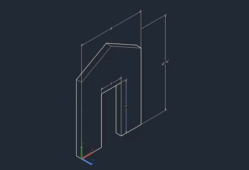
Create the 3d model of a wall as shown in Figure. Consider wall thickness as 9”.
Procedure:
- Open Autocad software and open new drawing With imperial units.
- Set the units as engineering and precision as 0'-0''
- Switch the work space to 3D modeling and set the view as South-West isometric.
- Use line tool to create a line, specify the first point of the line as 0,0,0
- Enter the next point of the line @3'4'',0,0
- Enter the following points to create the face profile of the wall.
- @0,0,7' @3',0,0 @0,0,-7' @3',0,0 and @0,0,10'
- Create a line, specify the first point as 0,0,0 and next point @0,0,10'
- Create a reference line to joint the top two end points of the profile.
- Create a line in the z-axis from the mid point of the created reference line at a distance of 2'6''. This is also a reference line.
- Create a line in the left top end point of the line and joint it to the end point of the reference line.
- Follow the same procedure to create a slope line in the other side.
- Erase the two reference line created.
- Use region command.
- Create surface as the created wall face.
- Type 'Region' in the command prompt.
- Select object in the command prompt and select the whole object.
- Switch the visual style to conceptual.
- Extrude the surface at a distance of 9'' in the Y-axis direction.
- Type 'Extrude' in the command prompt.
- Select the surface and enter the extrude distance as 9''
- Change the UCS and check the dimensions by creating dimensions in the model.
- Change to front view.
- Change the UCS select X and specify the rotation angle as 90 deg.
Output =