Creating various 3D Models like Furniture, Footing, Girder, Column drop with panel and Gable Wall in AutoCad
Q.1
Aim: -
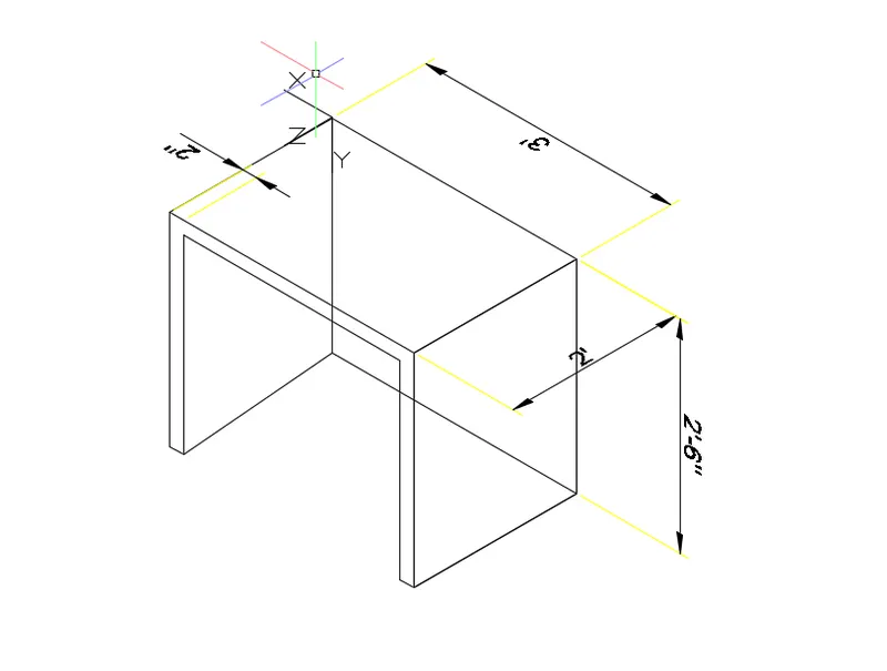
- To Create a 3D Furniture element Using Auto Cad
Procedure: -
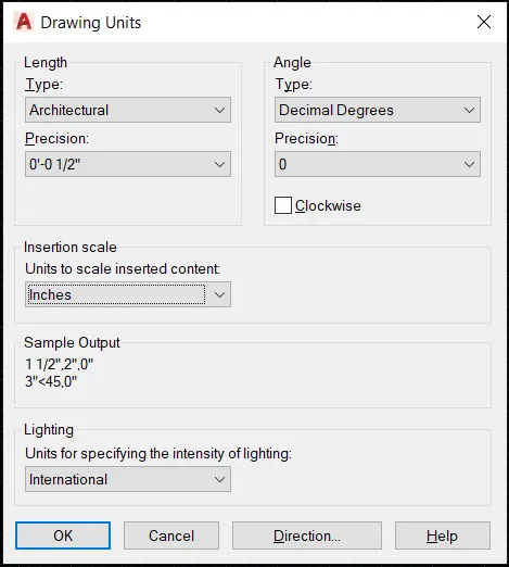
- Type Units in the Command Prompt and Press enter in the Unit Tab Select the Type as “architectural” and Insertion Scale as “Inches”
- Click Ok
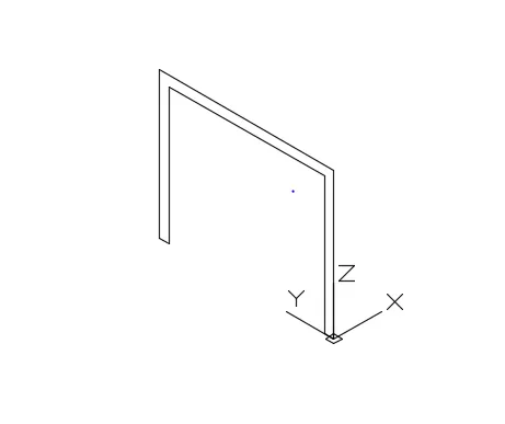
- Type Line in Command Bar and Press Enter
- Specify the Starting Point Using the Cursor
- Enter The Next Point as @0, 0, 2’.6” and Press Enter
- Enter The Next Point as @0, 3’,0and Press Enter
- Enter The Next Point as @0, 0, -2’.6” and Press Enter
- Enter The Next Point as @0, -2”, 0 and Press Enter
- Enter The Next Point as @0, 0, -2’4” and Press Enter
- Enter The Next Point as @0,2’8”,0 and Press Enter
- Enter The Next Point as @0, 0, -2’.4” and Press Enter
- Click Close From the Command Prompt
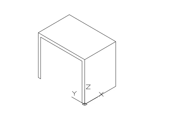
- Type Line in Command Bar and Press Enter
- Specify the Starting Point Using the Cursor
- Enter The Next Point as @2’ 0, 0 and Press Enter
- Enter The Next Point as @0,0,2’6” and Press Enter
- Enter The Next Point as @0,3’,0 and Press Enter
- Specify the Starting Point Using the Cursor
- Enter The Next Point as @-2’ 0, 0 and Press Enter
- Press Esc.,
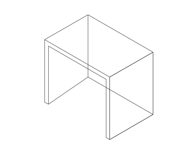
- Type 3D Face in the Command Prompt and Press Enter
- Specify the First Second Third and Fourth Point
- Press Enter
- Type Hide in the Command prompt and Press Enter
- Type 3D Orbit in the Command Prompt and Press Enter
- Click and Move the Cursor to Rotate the Work Space
- In the Ribbon Tab under the Co ordinate Select View From the Drop Down
- Type Dim linear Command prompt and Press Enter
- Specify the Starting and Ending Point to Display the Dimensions
Result: -
Q.2.
Aim: -
- To Create a 3D Model of Isolated Footing Using the Auto Cad
Procedure: -
- Type Units in the Command Prompt and Press enter in the Unit Tab Select the Type as “architectural” and Insertion Scale as “Inches”
- Click Ok
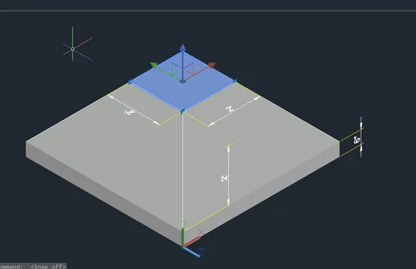
- Give the command of Rectangle Press Enter
- Specify the Starting Point Using Cursor
- Click the Dimensions from the Command prompt Enter the Length as 1’ and Breadth as 1’
- Press Esc.,
- Type Offset in the Command Prompt and Press Enter
- Enter the offset Distance as 2’
- Select the Rectangle to Offset
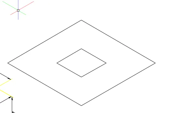
- Select the Extrude From the Ribbon tab and Select the previously Created Object
- Enter the Height to Extrude as 6” and Press enter
- Select the rectangle that was Created First and Type Move in the Command Prompt and Press Enter
- Select the object and Enter the Distance along Which the object ha to Be Moved
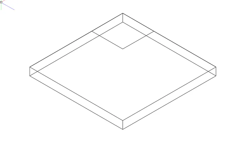
- In the Layer Properties Select the View as Solid
- Type 3d Face in the command Prompt and Press Enter
- Specify the 1st , 2nd , 3rd & 4th Point Press Enter
- Type Hide in the Command Prompt and Press Enter
- Type 3Dorbit in the Command Prompt and Press Enter
- Click ok and Move the Cursor to Rotate the Workspace
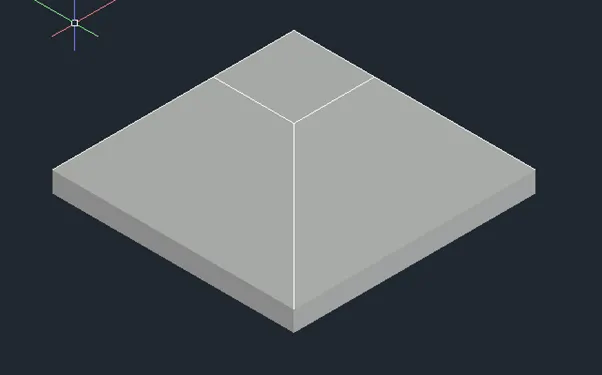
- In the Ribbon tab, Under the Co-Ordinate Select View From the drop Down
- Type Dim linear in the Command Prompt and Press Enter
- Specify the Staring and ending Point to Display the dimensions
Result: -
Q.3
Aim: -
- To Create 3D View of AASTHO type Girder Using Auto Cad
Procedure: -
- Type Units I he Command Prompt and Press Enter
- In the Unit tab Select the Type as “Architectural” and Insertion Scale as “ Inches”
- Click Ok
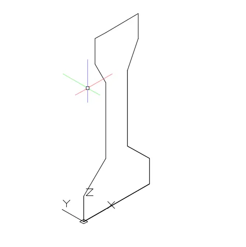
- Type Line in Command Bar and Press Enter
- Specify the Starting Point Using the Cursor
- Enter The Next Point as @0, 2”,0and Press Enter
- Enter The Next Point as @4”,0,6” and Press Enter
- Enter The Next Point as @0,0,1’6” and Press Enter
- Enter The Next Point as @-2”,0, 0 and Press Enter
- Enter The Next Point as @0, 0,0,6” and Press Enter
- Enter The Next Point as @-2’,0,0 and Press Enter
- Enter The Next Point as @0, 0,6” and Press Enter
- Enter The Next Point as @6”, 0, 0 and Press Enter
- Click Close From the Command Prompt
- Select the Created Object and type Mirror in the Command Prompt
- Select the Suitable Base Point
- Move the Cursor to Mirror the Object
- Select Line Tool From the Ribbon Tab
- Specify the Starting Point and Press Enter
- Enter the Next Point as @0,10’,0 and Press Enter
- Similarly Repeat the Same Method to Create the Line Projecting Backwards
- Press Esc.,
- Use Line tool from ribbon tab to Create required Object
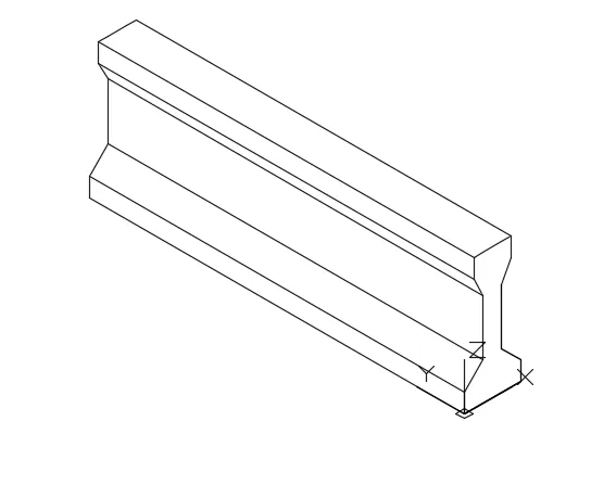
- Type 3DFace in the command Prompt and Press Enter
- Specify the 1st, 2nd, 3rd & 4th Point Press Enter
- Type Hide In the Command Prompt and Press Enter
- Type 3dorbit in the Command Prompt and Press Enter
- Click and Move the Cursor to Rotate the Workspace
- In the ribbon tab Under the Coordinate Select the View from the Drop down
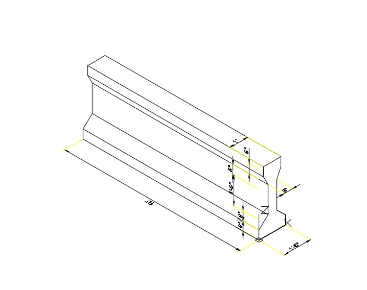
- Type Dim linear. in the Command Prompt and Press Enter
- Specify the Starting and ending Point to Display the Dimensions
Result: -
Q.4
Aim: -
- To Create 3d Model of drop Column with Panel Using Auto Cad
Procedure: -
- Type Units I he Command Prompt and Press Enter
- In the Unit tab Select the Type as “Architectural” and Insertion Scale as “Inches”
- Click Ok
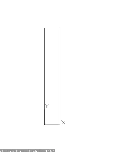
- Type Line in Command Bar and Press Enter
- Specify the Starting Point Using the Cursor
- Enter The Next Point as @0, 0,10’ and Press Enter
- Enter The Next Point as @1’6”,0,0and Press Enter
- Enter The Next Point as @0, 0, -10’ and Press Enter
- Enter The Next Point as @-1’6”,0, 0 and Press Enter
- Press Esc.,
- Type Line in Command Bar and Press Enter
- Specify the Starting Point Using the Cursor
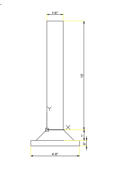
- Enter The Next Point as @-1’,0,1’ and Press Enter
- Enter The Next Point as @-1’0,0 and Press Enter
- Enter The Next Point as @0,6”,0 and Press Enter
- Enter The Next Point as @4’6”,0, 0 and Press Enter
- Enter The Next Point as @0,-6”,0 and Press Enter
- Enter The Next Point as @-1’0,0 and Press Enter
- Enter The Next Point as @-1’,0,-1’ and Press Enter
- Press Esc.,
- In the ribbon tab Under the Coordinate Select the View from the Drop down
- Type Dim linear. in the Command Prompt and Press Enter
- Specify the Starting and ending Point to Display the Dimensions
- Select the Top View from the Cube
- Select the rectangle tool From the ribbon tab
- Specify the starting Point and Press enter
- Select the Dimensions from the Ribbon tab
- Enter the Length and Breadth
- Press Esc.,
- Select Extrude the ribbon tab and Select the Circle Object
- Enter the Extrude Heights as -10’ and Press Enter
- Again now Select Rectangle Object and Click on extrude
- Enter the Extrude Height 6”
- In the Layer Properties Select the View as Solid
- Type 3d Face in the command Prompt and Press Enter
- Specify the 1st , 2nd , 3rd & 4th Point Press Enter
- Type Hide in the Command Prompt and Press Enter
- Type 3Dorbit in the Command Prompt and Press Enter
- Click ok and Move the Cursor to Rotate the Workspace
Result:-
Q.5
Aim: -
- To Create 3d Model of drop Column with Panel Using Auto Cad
Procedure: -
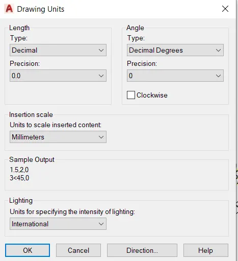
- Type Units I he Command Prompt and Press Enter
- In the Unit tab Select the Type as “Decimal” and Insertion Scale as “millimetrs”
- Click Ok
- Select Line Tool From the Ribbon tab
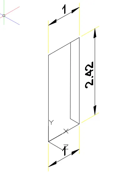
- Click on any Point and enter the Length as 1 keeping the Cursor in Y direction
- Enter the length as 2.42 and Click Keeping the Cursor in Y direction
- Enter the length as 1 and Click Keeping the Cursor in X direction
- Enter the length as 2.42 and Click Keeping the Cursor in -Y direction
- Enter the length as 0.3 and Click Keeping the Cursor in Z direction
- Press Esc.,
- Select Line Tool From the Ribbon tab
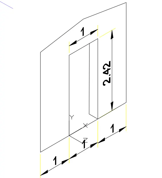
- Click on any Point and enter the Length as 1 keeping the Cursor in X direction
- Enter the length as 3 and Click Keeping the Cursor in Y direction
- Draw line of length of 0.3 unit Length From the midpoint of door Panel Connecting Previous Line
- From the Origin Draw a Line Using Line tool
- Enter the length as 3 and Click Keeping the Cursor in Y direction
- Draw and join the Line to the Midpoint Using Line Command
- Press Esc.,
- Select Line Tool From the Ribbon tab
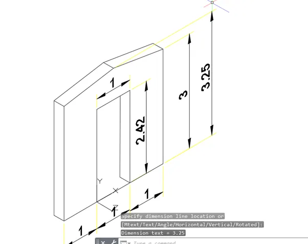
- From the Origin Draw Line Using Line Tool
- Click on any Point and enter the Length as 0.3 keeping the Cursor in-Z direction
- Enter the length as 3 and Click Keeping the Cursor in Y direction
- Enter the length as 1.5 and Click Keeping the Cursor in X direction
- Enter the length as 1.5 and Click Keeping the Cursor in X direction
- Press Esc.,
- Draw line of length of 0.3 unit Length From the midpoint of door Panel Connecting Previous Line
- Press Esc.,
Result:-