Creating various 3D Models like Furniture, Footing, Girder, Column drop with panel and Gable Wall in AutoCad
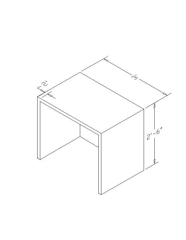
Q1. Create a 3D Furniture element as shown in the Figure. Assume dimensions which are missing.
AIM:-
To create a 3D furniture element as given in the figure and need to assume dimensions which are missing in the drawing.
INTRODUCTION:-
- The three-dimensional furniture element was drawn in the autocad using the different tools in the autocad
- 3D models are widely used anywhere in 3D graphics and CAD
- Their use predates the widespread use of 30 graphics on personal computers
- The 3d models are mainly preferable in thecivil engineering and When we design a building in the autocad then creating 3d models
COMMANDS USED:-
- Line command
- Rectangle command
- UCS command
- Dimlinear command
- Region command
- Extrude command
- Subtract command
- Box command
- Units command
- Dimstyle command
- 3Dface command
- 3D orbit command
- Hide command
- Explode command
- Move command
- Copy command
PROCEDURE:-
- Type UN and press enter
- Under Drawing Units, select Archetectural (feet and inches)
- Now the lower limit is set to 0', 0' and upper limit to 50', 50'
- Type Z enter to zoom and A enter to all.
- Now in settings selecting 3D Modelling and visual style control to 2D wireframe.
- A default layer for both dimension and lines was choosen with a colour .
- Type L and press enter
- Specify the first point as anywhere in the drawing.
- Line specify next point: @0,0,2'-6" and press enter.
- Line specify next point: @0,3',0 and press enter.
- Line specify next point: @0,0,-2'-6" and press enter.
- Line specify next point: @0,-2",0 and press enter.
- Line specify next point: @0,0,2'-4" and press enter.
- Line specify next point: @0,-3',0 and press enter.
- Line specify next point: @0,0,-2'-4", and press enter.
- Line specify next point: @0,-2",0 and press enter.
- Draw a rectangle at top of dimensions 2'-2" x3' and connect the rectangle corners as shown in figure.
- Type 3DFace command
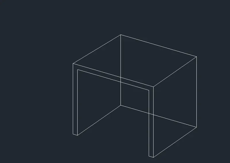
- Specify all the four point of the top rectangle and press enter followed by hide.
- Similarly do the 3DFace command to all the faces of the drawing
- The dimensions layers was made default now and using the DIMLIM command the required dimensions was marked.
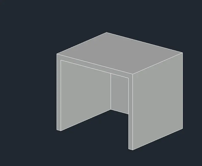
- Next click the custom visual styles at the top left corner of the drawing screen, and select the shaded option in the custom visual styles
RESULT:-
RESULT:-
Created the 3D model of the given furniture element with the proper dimensions by using the autocad.
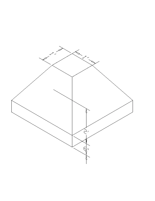
Q2. Create the 3d Model of an Isolated footing as shown in Figure.
AIM:-
To create the 3D model of an isolated footing in the autocad in detail
INTRODUCTION:-
- The three dimensional of isolated footing was drawn in the autocad using the different tools in the autocad
- 3D models are widely used anywhere in 3D graphics and CAD
- Their use predates the widespread use of 3D graphics on personal computers.
- The 3d models are mainly preferable in the civil engineering and when we design a building in the autocad then creating 3d models should be must
COMMANDS USED:-
- Line command
- Rectangle command
- UCS command
- Dimlinear command
- Region command
- Extrude command
- Substract command
- Box command
- Units command
- Dimstyle command
- 3Dface command
- 3Dorbit command
- Hide command
- Explode command
- Move command
- Copy command
PROCEDURE:-
- Type UN and press enter
- Under Drawing Units, select Archetectural (feet and inches)
- Now the lower limit is set to 0', 0' and upper limit to 50', 50'
- Type Z enter to zoom and A enter to all.
- Now in settings selecting 3D Modelling and visual style control to 2D wireframe.
- A default layer for both dimension and lines was choosen with a colour.
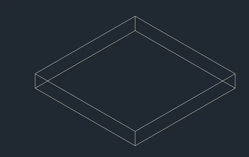
- Using the line command a square of size 1' was drawn.
- Type Region and press enter, and select the square created to convert it.
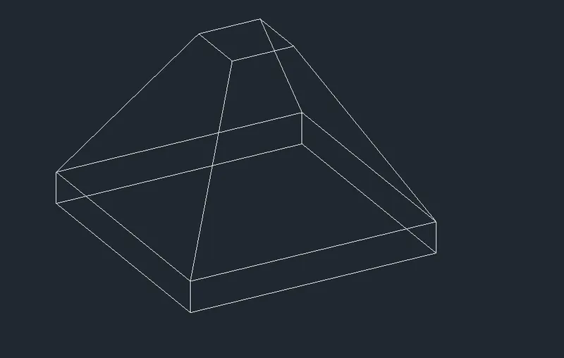
- Click on Extrude option in home tab and then select the object and click on Tamper, select the angle as b and and depth as 2".
- Type Region and press enter, and select the tampered rectangle created to convert it into a region.
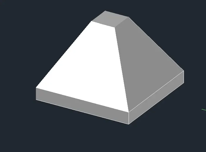
- Now extrude the rectangle at a depth of about 6".
- The visual style control was changed to hidden
- The dimensions layers was made default now and using the DIMLIM command the required dimensions was marked.
RESULT:-
RESULT:-
The given 3D model of the AASTHO Type Grider is drawn successfully by using the autocad.
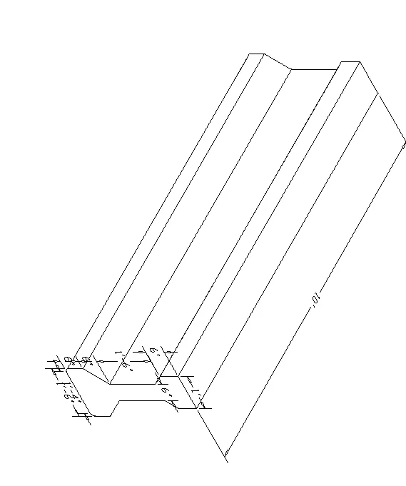
Q3. Create the 3D view of the AASTHO Type Girder.
AIM:-
To create the 3D model of AASTHO Type Grider in the autocad in detail
INTRODUCTION:-
- The three dimensional of AASTRO Type Grider was drown in the autocad using the different tools in the autocad
- 3D models are widely used anywhere in 3D graphics and CAD
- Their use predates the widespread use of 3D graphics on personal computers
- The 3d models are mainly preferable in the civil engineering and when we design a building in the autocad then creating 3d models should be must
COMMANDS USED:-
- Line command
- Rectangle command
- UCS command
- Dimlinear command
- Region command
- Extrude command
- Substract command
- Box command
- Units command
- Dimstyle command
- 3Dface command
- 3Dorbit command
- Hide command
- Explode command
- Move command
- Dist command
- Rulesurf command
- Plan command
PROCEDURE:-
- Type UN and press enter
- Under Drawing Units, select Archetectural (feet and inches)
- Now the lower limit is set to 0', 0' and upper limit to 50', 50'
- Type Z enter to zoom and A enter to all.
- Now in settings selecting 3D Modelling and visual style control to 2D wireframe.
- A default layer for both dimension and lines was choosen with a colour.
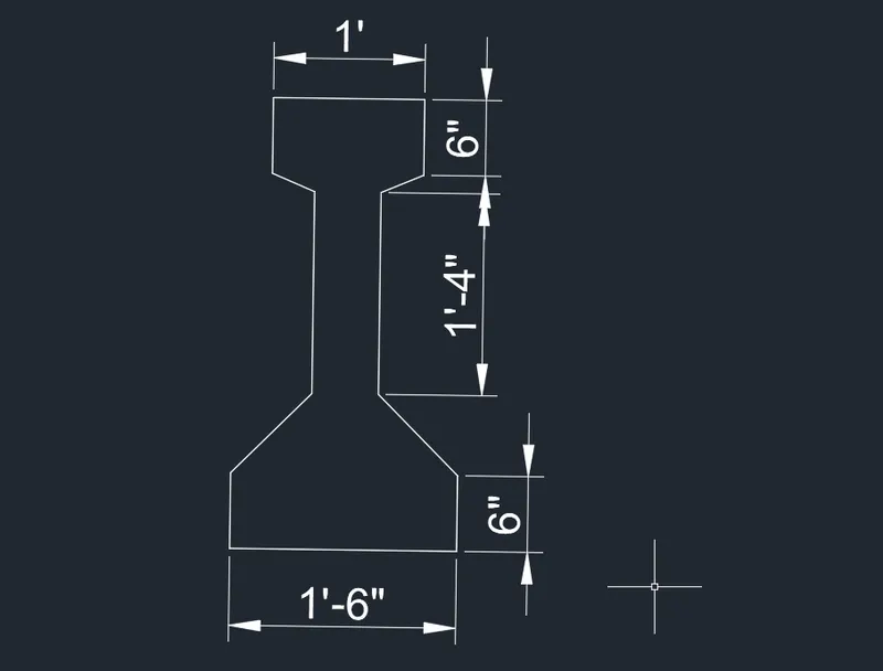
- Using the line command and given dimensions the points was plotted and the following image was obtained.
- Now using the Dimlim command the dimensions of the girder was made as shown.
- The dimensions layer was made hidden after this.
- Now Type Region and press enter, and select the Aastho type girder created to convert it into a region.
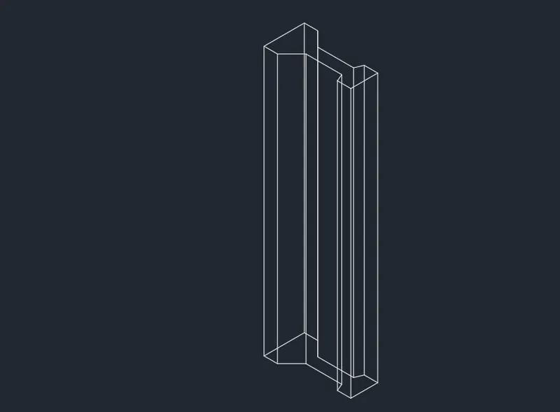
- Now extrude the Aastho type girder at a height of about 10".
- The visual style control was changed to hidden
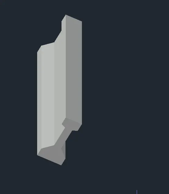
- The visual style control was changed to shaded with edges to obtain this view.
RESULT:-
RESULT:-
The given 3D model of the AASTHO Type Grider is drawn successfully by using the autocad.
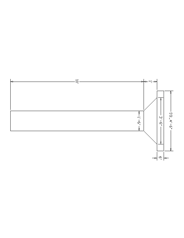
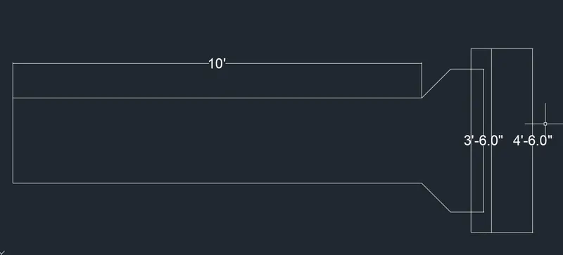
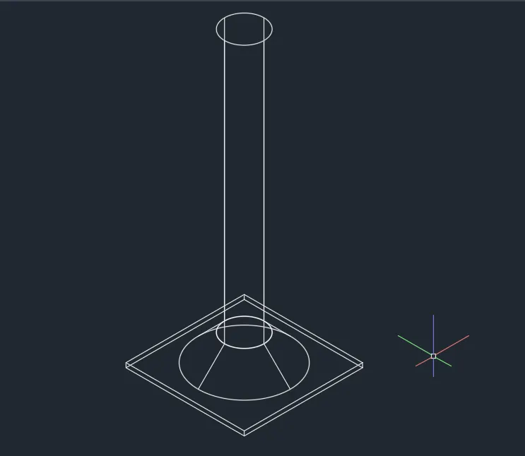
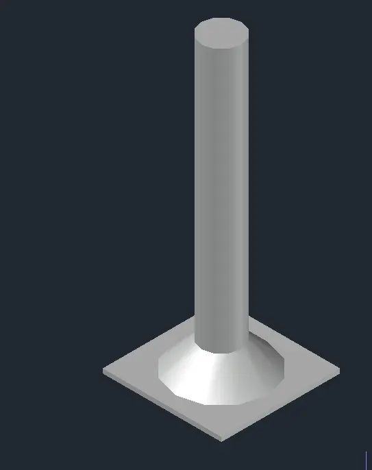
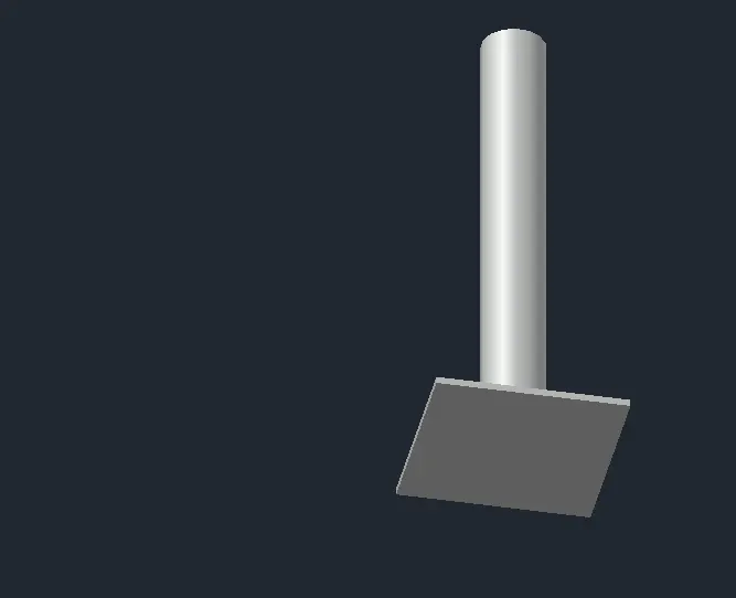
Q4. Create a 3d Model of a drop column with panel as shown in section and isometric view.
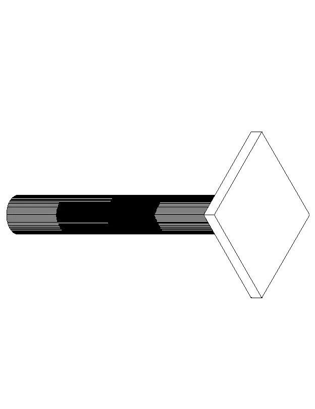
AIM:-
To create the 3D model of a drop column with panel in the autocad in detail
INTRODUCTION:-
- The three dimensional of Drop column with panel was drawn in the autocad using the different tools in the autocad
- 3D models are widely used anywhere in 3D graphics and CAD.
- Their use predates the widespread use of 3D graphics on personal computers
- The 3d models are mainly preferable in the civil engineering and When we design a building in the autocad then creating 3d models should be must
COMMANDS USED:-
- Line command
- Rectangle command
- UCS command
- Dimlinear command
- Region command
- Extrude command
- Substract command
- Box command
- Units command
- Dimstyle command
- 3Dfate command
- 3Dorbit command
- Hide command
- Explode command
- Move command
- Copy command
- Rulesurf command
- Plan command
PROCEDURE:-
- Under Drawing Units, select Archetectural (feet and inches)
- Now the lower limit is set to 0', 0' and upper limit to 50', 50'
- Type Z enter to zoom and A enter to all.
- Now in settings selecting 3D Modelling and visual style control to 2D wireframe.
- A default layer for both dimension and lines was choosen with a colour.
- sing the line command a square of size 4'-6" was drawn.
- Type Region and press enter, and select the square created to convert it.
- Click on Extrude option in home tab and then select the square and at a height of 2".
- Type hide to hide the portions of the surface
- Now a circle is drawn of diameter 3'-6" at the centre position of the rectangle.
- Type Region and press enter, and select the circle created to convert it.
- Click on Extrude option in home tab and then select the circle and click on Tamper, select the angle as 45 and and height as 2".
- Now explode the tampered circle and convert the top circle into a region.
- Click on Extrude option in home tab and then select the circle and at a height of 10'
- The visual style control was changed to hidden
- The visual style control was changed to shaded with edges to obtain this view.
RESULT:-
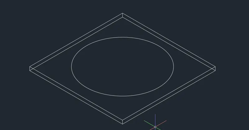
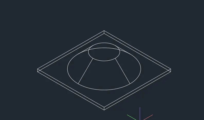
RESULT:-
The given 3D model of drop column with panel is drawn successfully by using the autocad.
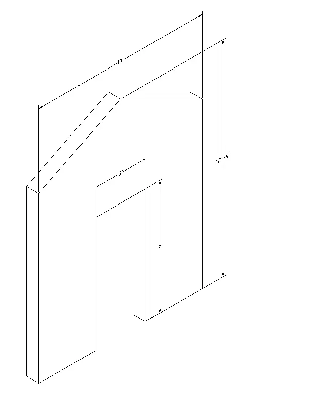
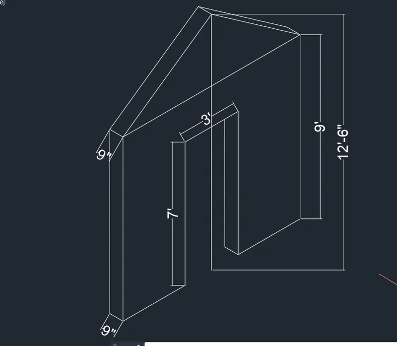
Q5. Create the 3d model of a wall as shown in Figure. Consider wall thickness as 9”.
AIM:-
To create the 3D model of a wall by aming the wall thickness as 9” in the autocad in detail
INTRODUCTION:-
- The three dimensional of a wall is drawn in the autocad using the different tools in the autocad
- 10 models are widely used anywhere in 30 graphics and CAD
- The se predates the widespread use of 30 graphics on personal computers The 3d models are mainly preferable in the civil engineering and When we designs a building in the autocad then creating 3d mode
COMMANDS USED:-
- Line command
- Rectangle command
- UCS command
- Dimlinear command
- Region command
- Extrude command
- Substract command
- 3Dorbit command
- Hide command
- Explode command
- Move command
- Copy command
- Dist command
- Plan command
PROCEDURE:-
- Type UN and press enter
- Under Drawing Units, select Archetectural (feet and inches)
- Now the lower limit is set to 0', 0' and upper limit to 50', 50'
- Type Z enter to zoom and A enter to all.
- Now in settings selecting 3D Modelling and visual style control to 2D wireframe.
- A default layer for both dimension and lines was choosen with a colour.
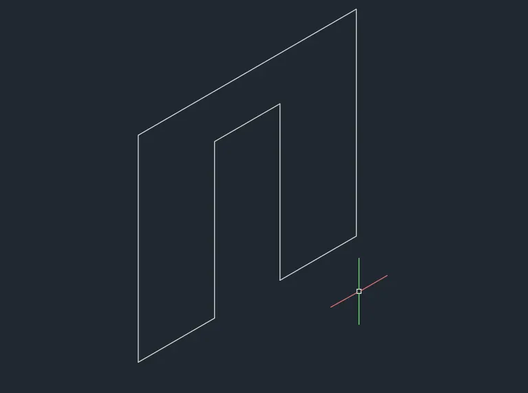
- Using the line command and given dimensions the points was plotted and the following image was obtained.
- Drafting was done in the same manner as done in Task 1.
- Draw a line of 10' in the X direction
- Specify the center of line 1'
- Draw a line of 1'5" in both directions with a height of 7' to draw the door of the wall
- The thickness of the wall is considered as 9"
- Draw the top of the wall on the distance of 12'6" from the bottom. offset 9" to draw the roof of the wall
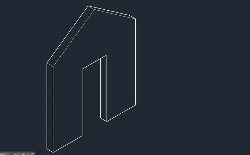
- Type Region and press enter, and select the model created to convert it.
- Click on Extrude option in home tab and then select the model and wall extrude 9".
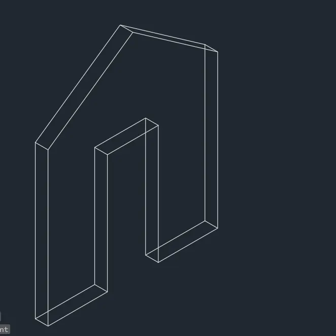
- The visual style control was changed to hidden
- The visual style control was changed to shaded with edges to obtain this view.
- Using the DIMLIM command the dimensioning
RESULT:-

RESULT:-
The given 3D model of a wall is drawn successfully By using the autocad.