Creating various 3D Models like Furniture, Footing, Girder, Column drop with panel and Gable Wall in AutoCad
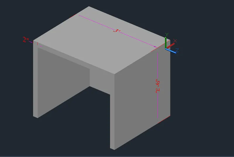
1. Create a 3D Furniture element as shown in the Figure. Assume dimensions which are missing.
AIM:
To create 3D model for a furniture element
INTRODUCTION:
- AutoCAD is a three-dimensional CAD software that is used widely for all tpye of projects
- AutoCAD offers an exclusive range of commands and functions both for 3D as well as 2D modeling and srawing with an various set of tools
- 3D is all about the third coordinates which is Z axis, While using 2D we only cares about X and Y axis and most of the times coordinates are used
- Whereas,while working with 3D the user uses all the coordinates which makes the work even more easier
- Three dimensional CAD is used for drafting our project relevsnt to the reality
- It is the process of creating a mathematical representation of any surface using a various tools
- An architectural 3D model is much more intresting and realistic then 2D model
- In 3D design, the user gets to know the physical dimensions of the objects and their distance in relation to other objects in the total layout. This feature helps enormously to see and modify arrangements of object based on their sizes.
COMMANDS USED:
- UCS
- Extrude (EXT)
- Box
- Union (UNI)
- Substract (SU)
- Presspull (PRESS)
- Intersection
- 3DMove (3M)
- 3DRotate (3R)
- 3d orbit (3DO)T
- Loft
- Polyline (3DPOLY)
- Sweep
- Cone
- Boundary
- Region
UCS:
To define your UCS manually, click two points to define the orientation of the X axis. To set your ucs based on the angle of an object in your drawing, such as polyline click that object as you move your cursor up or down a 90 degree line will extending from the object you selected
EXTRUDE:
The extrude command will extrude a 2D object into a 3D object
It creates a 3D solid form an object that encloses an area, or a 3D surface from an object with open ends. Objects can be extruded orthogonally from the plan of the source 2D object in a specified direction, or along a selected path
When using extrude command the original 2D object will be removed from the drawing
BOX:
The BOX command will allow you to create a 3D box by selecting 3 points i,e length, width and height
PRESSPULL:
The presspull command will extrude a 2D object into a 3D object, or extend a 3D surface
When using the presspull command with a 2D object, the 2D object will remainin the drawing
UNION:
The UNION command allows you to join the 2 or more objects into a singkle objects
Modify > solid editing > union
SUBTRACT:
This command is used to remove the objects present together
If two objectws are placed one above the another and if we want to remove one of them then we go with command SUB select the source object press enter then select the object that you want to remove
And a single new 3D solid object is created
3DMOVE:
The 3Dmove command allows you to move the objects in either X, Y or in Z-axis
Select the objects and subobject you want to move using the following methods - press and hold ctrl to select subobjects face, edges and vertices and release ctrl to select whole object
3D ORBIT:
Command 3DO to get 3D orbit cursor by this you can rotate the objects in all directions and see all sides with fixed axis
You can go with command or press shift + the whwwl of the mouse and then move the mouse you will jump into 3D orbit
BOUNDARY:
It creates a region or a polyline from enclosed areas
Command BO options are displayed, the interior point that you specify uses the surrounding and interior objects to create closed polyline and region.
Hometab > draw panel > click boundary or command boundary
REGION:
It converts objects that encloses an area into 2d region object, it basically a closed boundary that these objects that we've got in drawing are changes to a region
PROCEDURE:
STEP1
- Open autoCAD with imperial system as units , then command Unit set to engineering and precision - 0'-0''
- Set lower and upper limits by command LIMITS, then apply zoom-all enter
- And go to workspace manager and select 3D modeling
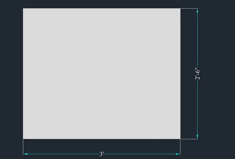
- Create a box by command BOX or by clicking on toolbar, in 2D wireframeclick on length as 3' and specify width as 2'6''. Then specify the height of the box as 2'6''
STEP2
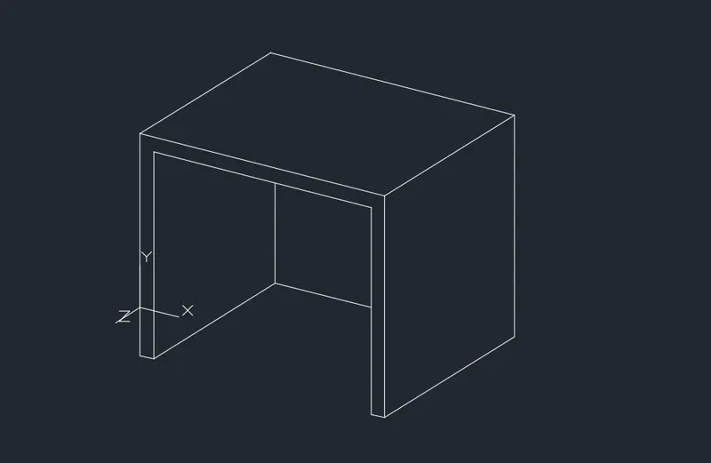
- Select the front face, command UCS give the x and y coordinated in the front face horizontally and vertically respectively or click on face and select the front face, Then type command PLAN so that the front face is aligned correctly.
- Then draw a line of 2'' from the right side of the front view. by rectangle command, draw a rectangle of dimension 32'' and 2'4'' as the thickness is given as 2''
- Move command is used to move the created rectange into a line 2'' line drawn earlier place over that line
- Delete the 2'' line that created and with 3DO orbit the object and select the rectangle
- Command EXT to extrude the rectangle to -z axis and give value as -2'4'' leaving 2'' thickness
- Now command SUB is used to subtract the smaller extruded rectangle in 2d wireframe model
STEP3
- Command DIMSTYLE and set the dimension style and font style and give the text height to 1'' and Arial font size to 1''
- By placing the ucs on required particular position the dimensions are measured and marked
- Then make the whole object to region using REG command and shaded is used
RESULT:
The 3D model of furniture element is created.
2. Create the 3d Model of an Isolated footing as shown in Figure.
AIM:
To create a three-dimensional model of a isolated footing
PROCEDURE:
STEP1
- Open autoCAD with imperial system as units , then command Unit set to engineering and precision - 0'-0''
- Set lower and upper limits by command LIMITS, then apply zoom-all enter
- And go to workspace manager and select 3D modeling
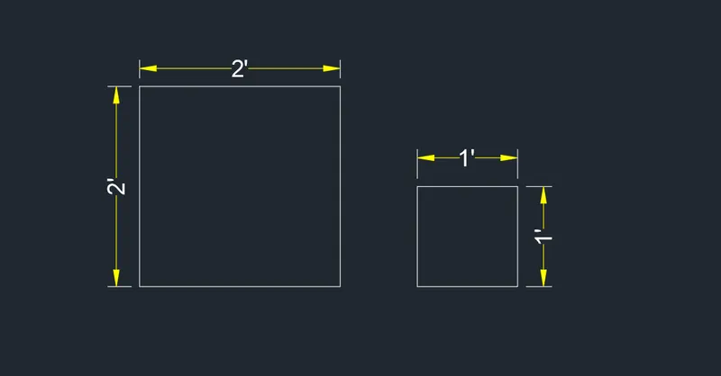
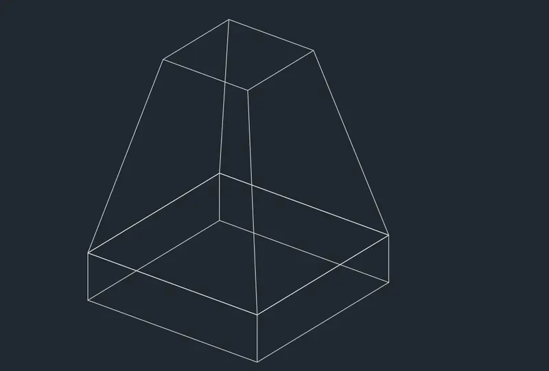
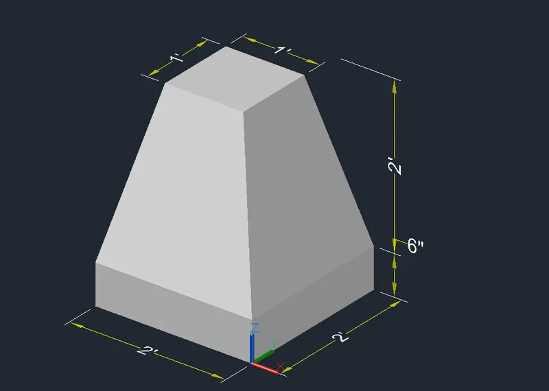
- Create a rectangle of dimensions 2' x 2' and and another rectangle of dimension 1' x 1' in the top view
STEP2
- By using command M, move the 1'x1' rectangle to a middle of the 2'x2' rectangle and from there move the smaller rectangle to 2' along in Z-directions
- By specifying the value as @0,0,2', keeping ortho on
- Click on the loft in toolbar or command loft and click the two rectangle created to loft
- Again go to top view and create rectangle on top of 2'x2' rectangle and give the extrude height value as -6'' as the direction of extrusion is in z-axis
- Command HIDE to hide the inner lines are used
- Then command DIMSTYLE and set the dimension height and text font as required the dimensons are made
RESULT:
The Three-dimensional model of isolated footing is created.
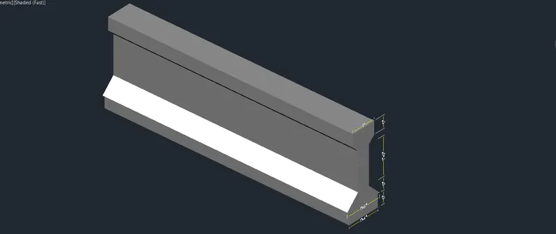
3. Create the 3D view of the AASTHO Type Girder.
AIM:
To create a three-dimensional view of AASTHO type girder using various drawing tools in 3D modeling
PROCEDURE:
STEP1
- Open autoCAD with imperial system as units , then command Unit set to engineering and precision - 0'-0''
- Set lower and upper limits by command LIMITS, then apply zoom-all enter
- And go to workspace manager and select 3D modeling
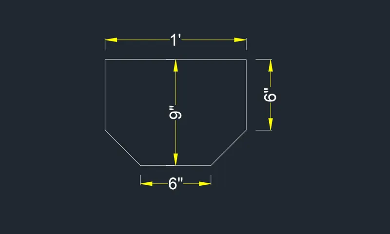
- Using line command the lines are created with keeping X and Y axis on front view
- Draw a line of 1' that is the top width of the girder then draw a 6'' towards downward
- With keeping snap on draw a line of 1' and offset 3'' on both side such that the width of web becomes 6''
- Give the tapper distance and join the web and the flange. Mirror the same on the other side
STEP2
- The web is drawn with the height of 1'6'', offset the distance 1'6'' from the end of tapering of the flange portion 1'' .Delete the center line for the offset and also trim off the extra line in flange.
- Extend the web to the offset line. Again offset 6'' from the last line and tapper the side. Mirror the tapered portion to the other side.
- The side should be tapered such that the bottom should be 1'6'', draw a center line and offset 9'' on both sides, then join the tapper.
- Offset 6'' downwards from the bottom horizontal line to define the height. To draw the taper at bottom 1'4'' from the center draw a line and offset to 8'' on both sides
- Extend the 6'' offseted line and trim the rest of the lines. Draw the vertical line downwards and tapering also.

STEP3
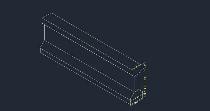
- The view is changed to top by using 3DO command and by using REG command the girder is said to region
- Then using "EXT" command the girder gets extruded y axis
- Then by using DIMSTYLE command the dimension settings are done and values are measured
RESULT:
The Three-dimension model of AASTHO type girder is created using various AutoCAD tools.
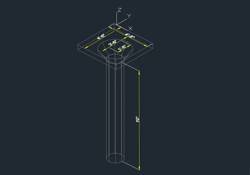
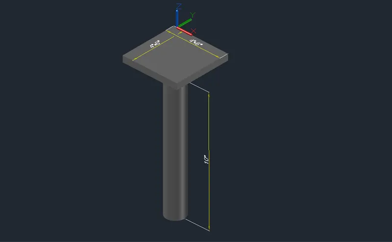
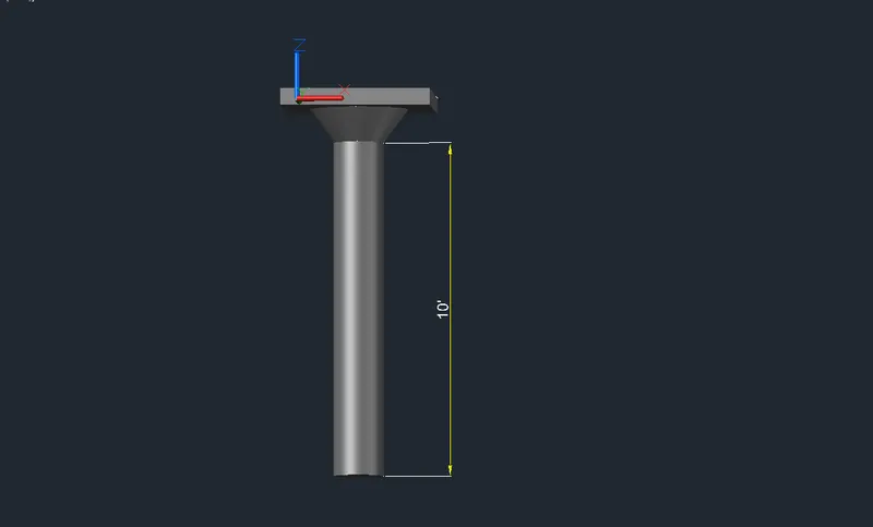
4. Create a 3d Model of a drop column with panel as shown in section and isometric view.
AIM:
To draw a 3D model of a drop column with panel section and show its isometric view.
PROCEDURE:
STEP1
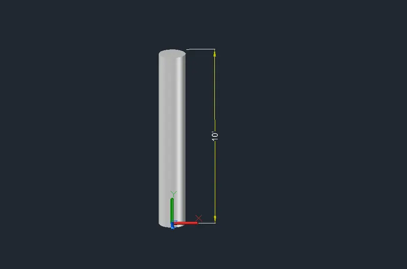
- Create a circle of diameter 1'6'' in the top view, create a region of this circle and by using extrude command the circle is extruded to a distance of -10' in -z axis
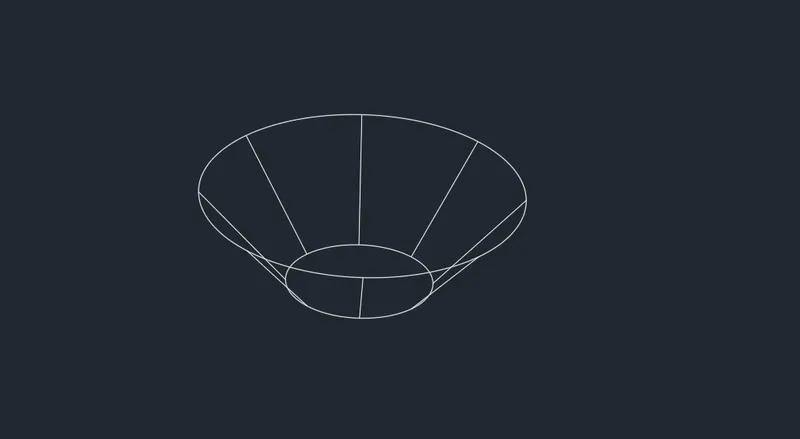
- Create a cone by using cone command or in toolbar- cone, create a circle by clicking diameter and give the base diameter of about 1'6''
- Then click on top radius and give the value of 1'6'' and give the height of the cone as 1'.
- By using REG command the region is created over the cone
STEP2
- Place the frustum of cone on the top of the extruded circle, the column in the front view, with snap option place the center of two object coincide, also place the center of frustum with center of column in the top view
- Then create a rectangle of of size 4'6'' x 4'6'' and make as region then extrude the rectangle to a height of 6'' in -z direction
- By 3do command the side view of rectangle is shown
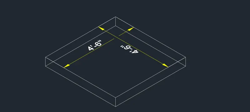
- Move the rectangle drawn over the cone in top view place the rectangle at the center of cone and also adjuss in the front view or give move command and give coordinates as @0,10',0 as the rectangle is at bottom in the front view
- Then the dimensions are made using DIMLIN command
RESULT:
The 3D model of a drop column with panel has been drawn section and isometric view is also shown
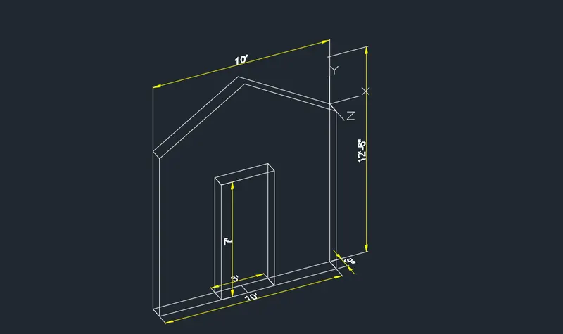
5. Create the 3d model of a wall as shown in Figure. Consider wall thickness as 9”.
AIM:
To draw a 3D model of wall.
PROCEDURE:
STEP1
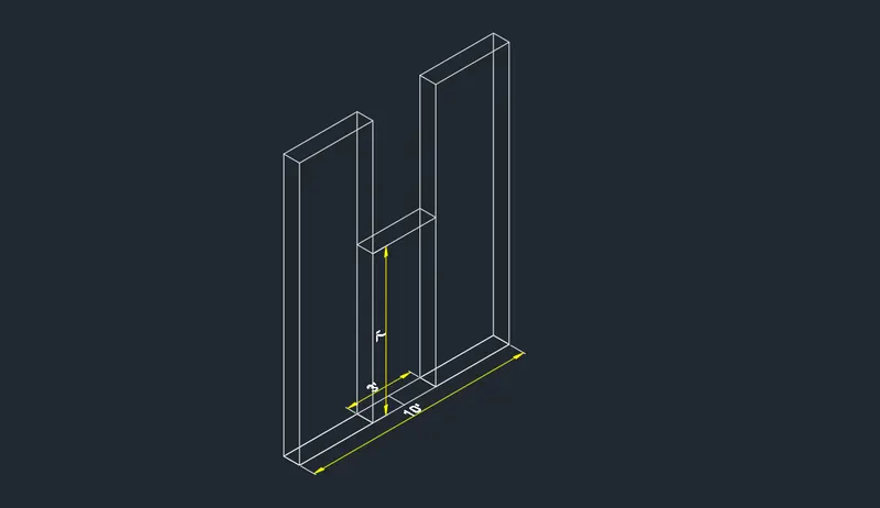
- Draw a rectangle of 10'x9'' create a line in the center and offset 1.6''. on both side as 3'' is the width of door opening
- Use the command "BO" to make a boundary and create a region on either sides
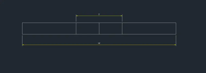
- Using EXT command extrude the region to a height of 12'6'' as total height of the door
- Create a rectangle in place of door in the top view. Move the rectangle in z axis at a height of 7' from the bottom, to create a door size.
- The door size of 3' x 7' is now created
- Go to front view and draw a line from the center of the moved line of door. Draw slanting line from the total height from the center line intersecting the edge.
- Mirror the line to a another side draw a horizontal line to join
- Trim off the excess line at the center line and join the triangle with join command, Create a region by using reg command in triangle created.
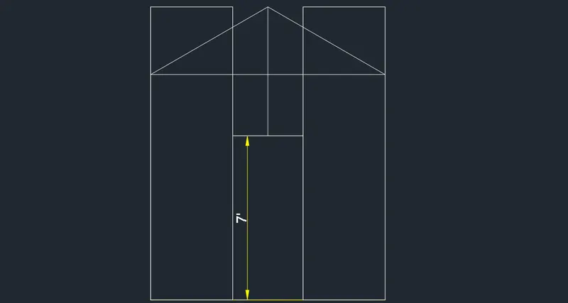
- Select the extruded rectangle and with the help of grip bring it down to the level of triangle base on both sides. Extrude the rectangle of door to a height equal to base of triangle
- By using DIMLIN comand and Ucs command dimensions are made by palcing ucs on each required positions
RESULT:
THE 3D model of wall with door is drawn.
OVERALL RESULT:
- 3D model of furniture element is created.
- 3D model of isolated footing is drawn
- 3D model of AASTHO type girder is drawn
- 3D model of Drop column with panel has drawn
- 3D model of wall door is created