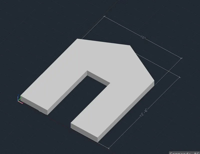
Creating various 3D Models like Furniture, Footing, Girder, Column drop with panel and Gable Wall in AutoCad
1.
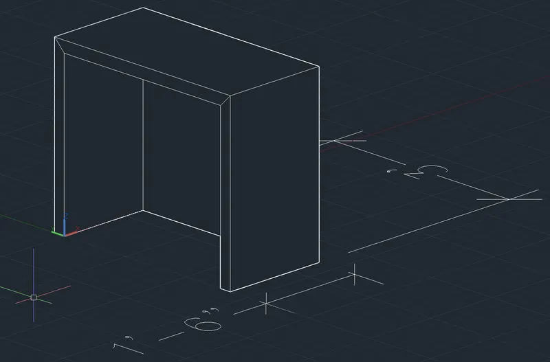
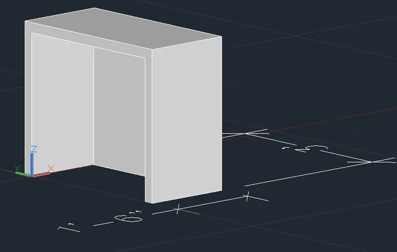
AIM:- Create a 3D Furniture element as shown in the Figure. Assume dimensions which are missing.
PROCEDURE:-
- Select the 3D modeling tool from the bottom.
- Now, for lines specify the first point and then start drawing the full furniture shape in 3D view.
- Now put the points of the shape and draw the shape.
- The cordinates entered are as follows, {(@1'4",0,0), (@0,-2'8",0), (@-1'4",0,0), (@0,-2",0), (@1'6",0,0), (@0,3',0), (@0,-1'6",0) }.
- Now draw the Eight vertical lines, of which inner four lines are of (2'4") height, and outer four lines are of (2'6") height.
- Now join all the vertical lines and form a furniture table like structure.
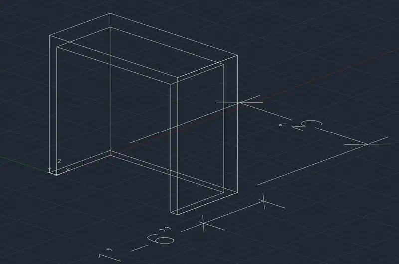
- Now Enter the command "3Dface" to create a face on the furniture lines.
- For face select the four points of the drawing to which face is to be applied and then press enter and the face is applies.
- For seeing the face select "Hidden Lines" or "Shaded" from the top left corner of the autocad page.
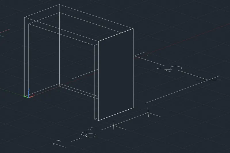
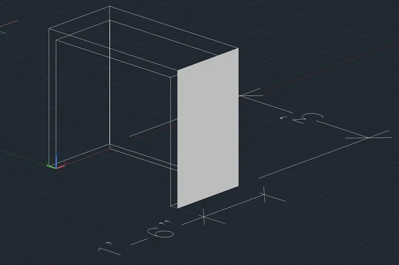
- Now do the same for the rest of the faces and create a perfect furniture element.
- The final drawing is as below.
--------------------------------------------------------------------------------------------------------------------------------------
2.
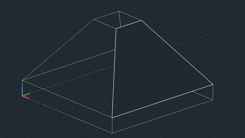
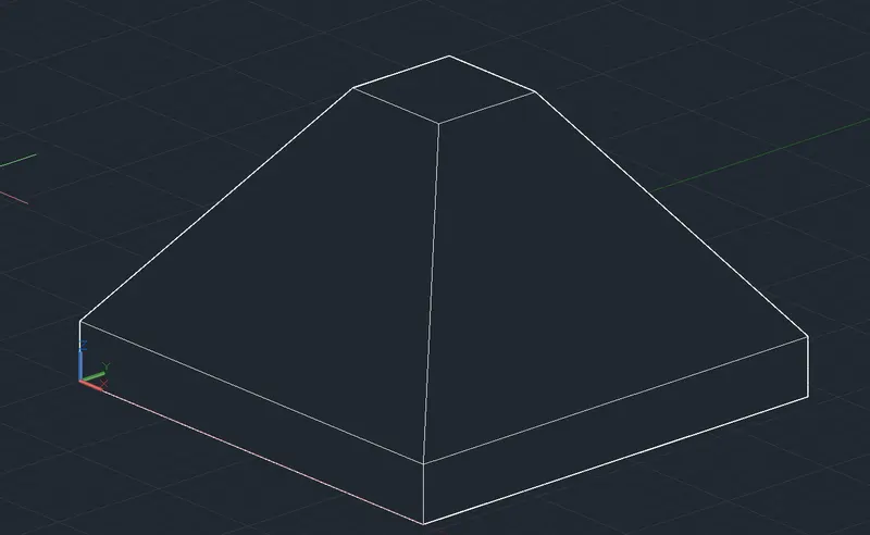
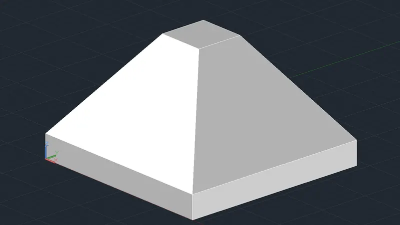
AIM:- Create the 3d Model of an Isolated footing as shown in Figure.
PROCEDURE:-
- Draw a rectangle of "4'X4'".
- Now select the rectangle and copy to the point (@0,0,6")
- Now join all the corners of both the rectangles in such a way that it forms a slab.
- Now give the offset of 3' to the upper rectangle and then move the newwly created rectangle with the help of offset command to the (@0,0,2').
- Now join all the corners and create a trapezoidal shape.
- Now Enter the command "3Dface" to create a face on the foundation.
- For face select the four points of the drawing to which face is to be applied and then press enter and the face is applies.
- For seeing the face select "Hidden Lines" or "Shaded" from the top left corner of the autocad page.
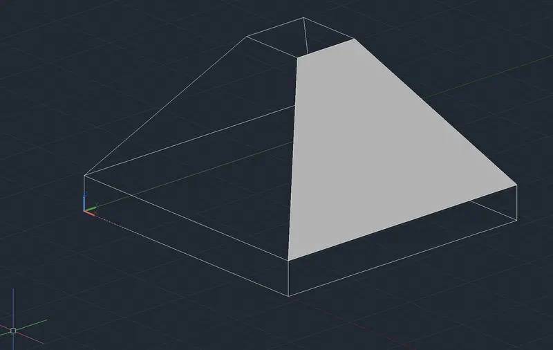
- Now do the same for the rest of the faces and create a perfect foundation drawing.
- The final drawing is as below.
-----------------------------------------------------------------------------------------------------------------------------------------
3.
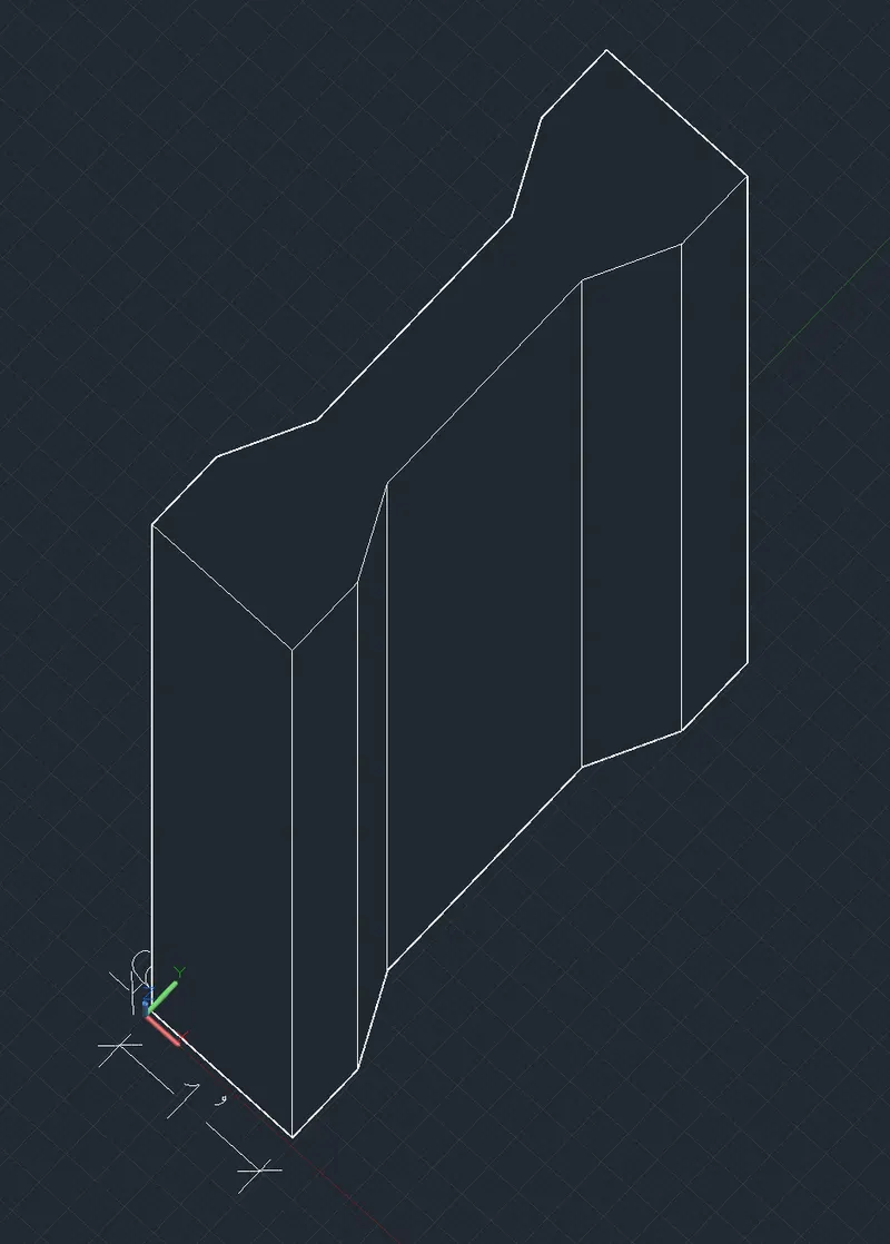
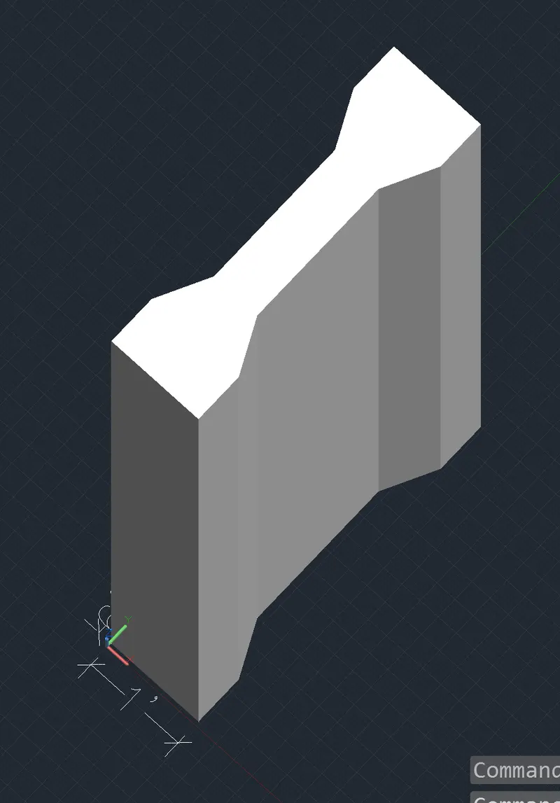
AIM:- Create the 3D view of the AASTHO Type Girder.
PROCEDURE:-
- For the AASTHO type girder following process is followed.
- Now for the AASTHO girder put the top plane and draw the shape.
- Now enter the line command and then specify the first point and then follow the respective co-ordinates. { (@0,6",0), (@3",6",0), (@0,1'6",0), (@-3",6",0), (@0,6",0), (@1',0,0), (@0,-6",0), (@0,6",0), (@-3",-6",0), (@0,-1'6",0), (@3",-6",0), (@0,-6",0), Close the shape.}
- now select the shape and enter the Join command to ensure the shape remains closed.
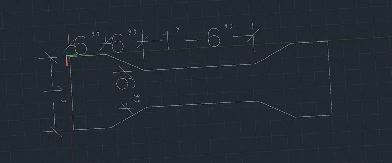
- Now select the extrude tool and then select the shape and then press enter and then put the corsur in the desired direction and enter the value for the height of the exturtion.
---------------------------------------------------------------------------------------------------------------------------------------
4.
AIM:- Create a 3d Model of a drop column with panel as shown in section and isometric view.
PROCEDURE:-
- for the drop column start from the base.
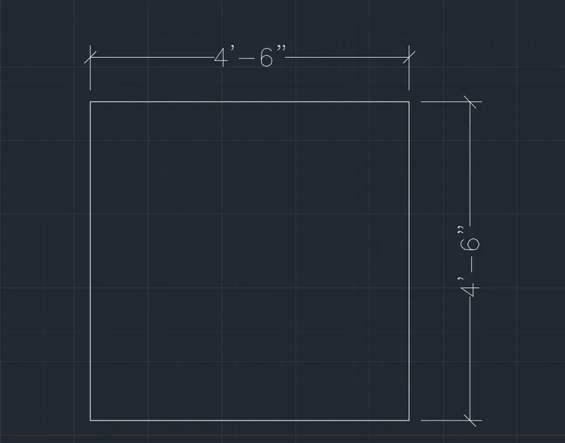
- For base enter the rectangle command then specify the start point and create a rectangle of (4'6" x 4'6").
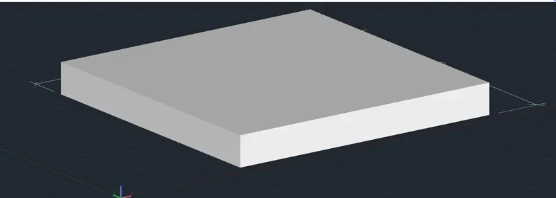
- Then select the extrude and then select the square and then enter the exturtion height of 6".
- Now select the centroid of the top rectangle and and then draw a circle of diameter (3'6").
- Now draw a circle of diameter (1'6") with the same centre point.
- Now move the smaller circle to the (@0,0,1').
- Now come in the front view and draw one line joining the quardents of both the circle.
- Now draw a straight line joining the centres of the circles.
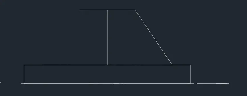
- Now enter the revolve command and then select the trapezoidal line as the line to be revolved and then select the centre line as the axis through which the other line is going to revolve.
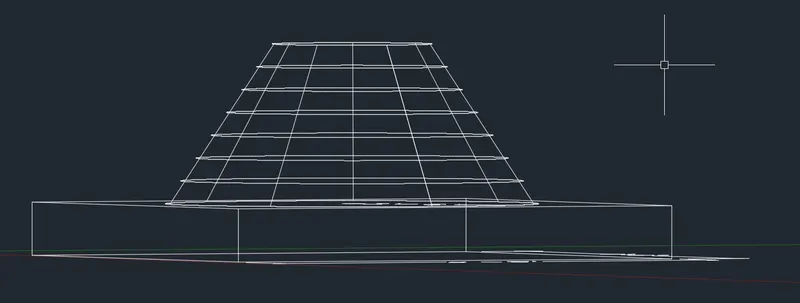
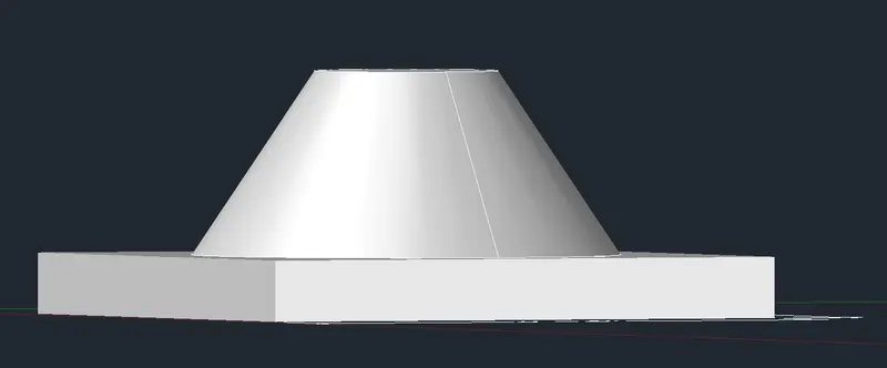
- Now draw a circle at the top of diameter (1'6").
- Now select the extrude tool and then select the circle and then put the height of the (10').
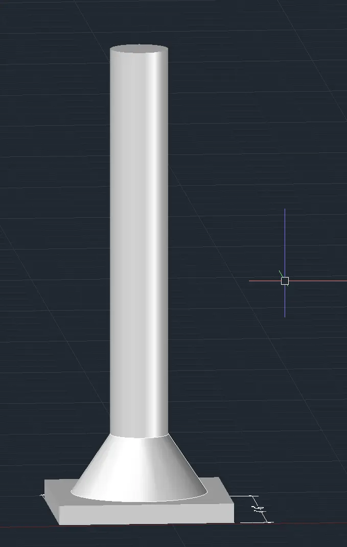
-------------------------------------------------------------------------------------------------------------------------------------
5.
AIM:- Create the 3d model of a wall as shown in Figure. Consider wall thickness as 9”.
PROCEDURE:-
- Draw the given shape with the help of line.
- Specify the start point for the line and then enter the following co-ordinates to finish the drawing. {(@0,10',0), (@5',2'6",0), (@5',-2'6",0), (@0,-10',0), (@3'6",0,0), (@0,7',0), (@-3',0,0), (@0,-7',0), close the shape.}
- Now select the whole shape and then enter the command "join" to ensure that the shape is closed.
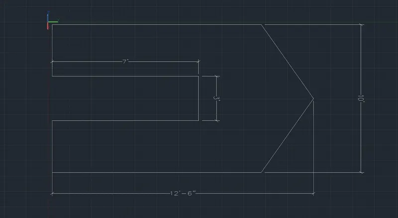
- Now select the extrude option and then select the drawn wall.
- Then enter the value of height of extrution as (9") to show the wall.