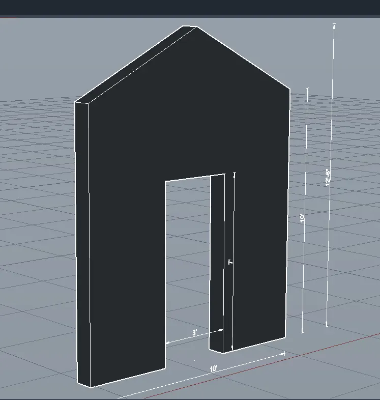
Creating various 3D Models like Furniture, Footing, Girder, Column drop with panel and Gable Wall in AutoCad
1.
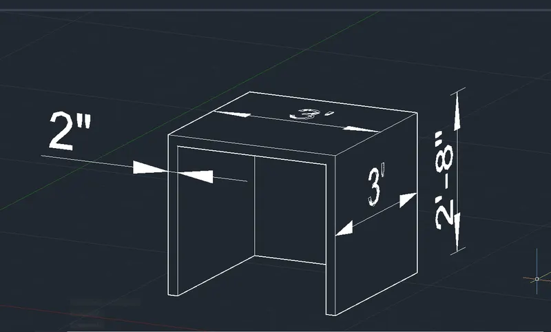
AIM: To Create a 3D Furniture element
PROCEDURE:
1. First change the unit to engineering and inches
2. Then create a plan for the table with the help of the polyline command
3. Then turn it into REGION with the help of the region command
4. With the help of EXTRUDE command extrude it in the z-axis as per the given height
5. Then create another cube of the same size but with a 2" depth Place it on the top of the table
6. Convert it into the region
7. Then with the help of the UNION command make it a single entity
RESULT:
2.
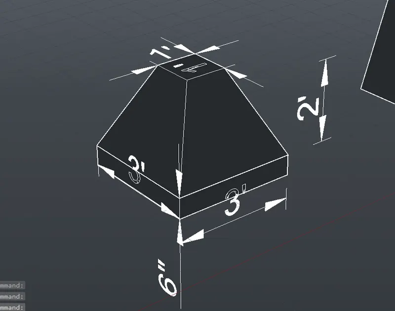
AIM: To Create the 3d Model of an Isolated footing
PROCEDURE:
1. First create a box of size 3'x3'x6" with the help of the BOX command
2. Then convert it into the region
3. Then with the help of The PYRAMID command create a pyramid and convert it into a region
4. After that use the UNION command to convert it into a single entity
5. With the help of the DIMLINEAR command determine the dimension of the geometry.
RESULT:
3.
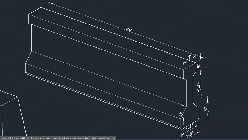
AIM: To Create the 3D view of the AASTHO Type Girder.
PROCEDURE:
1. With the help of the POLYLINE command create the face of the grider. As per the given dimension
2. Use the UCS command to determine the face of the geometry
3. After creating it Convert it into a region
4. Use the SWEEP command to enlarge it to 10'
5. Then use the DIMLINEAR command to determine the dimension of the geometry
RESULT:
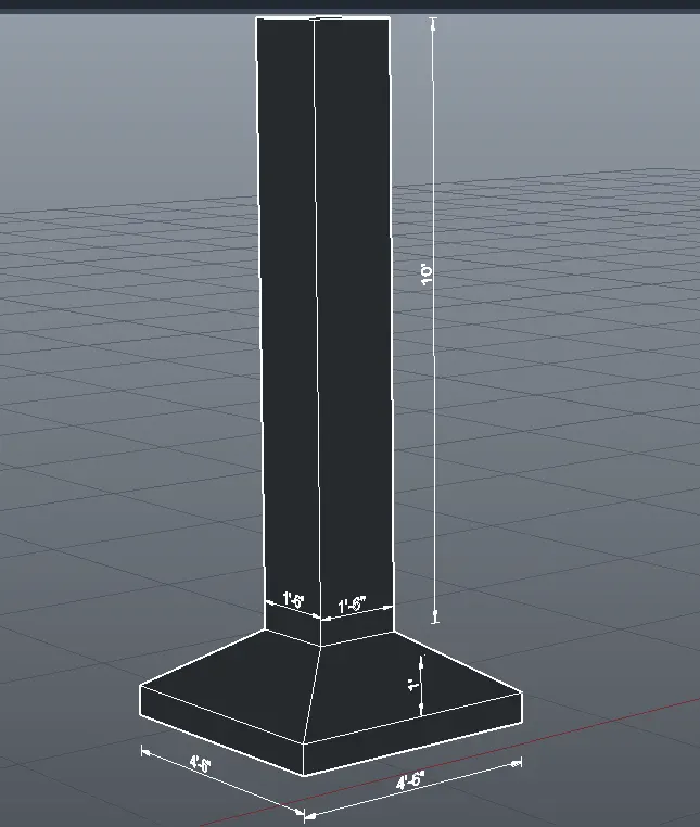
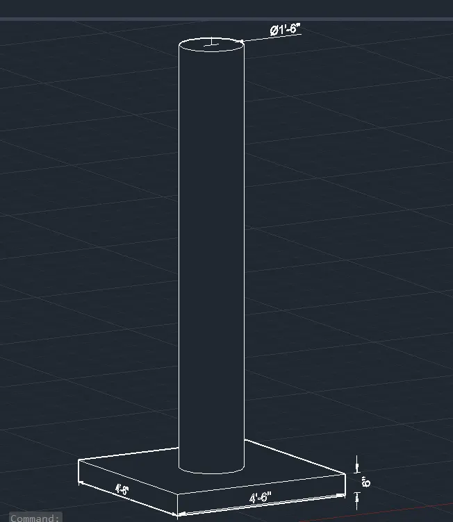
4. AIM: To Create a 3d Model of a drop column with the panel
PROCEDURE:
1. First create a box of size 4'6"x4'6"x6"
2. Make it a region
3. At the center of a box create a steep portion with the help of the PYRAMID command
4. Then create a column with help of BOx Command ( And use CYLINDER Command to create a circular column)
5. With the help of the UNION command Convert it into a single entity
6. Then use the DIMLINEAR command to determine the dimension of the geometry
RESULT:
1. Rectangular shape column
2. Circular shape column
5.
AIM: To Create the 3d model of a wall
PROCEDURE:
1. Create a plane for a wall of thickness 9"
2. Determine the wall position inside the wall
3. Convert it into a region
4. Drage it in z-axis With the extruded command
5. Subtract the wall dimension with the help of SUBTRACT Command to provide an opening
6. For a pitched roof determine the center point of the wall Give it a thickness of 9"
7. Join it with the wall end-to-end vertex and then make it a region
8. With the help of the SWEEP command determine the thickness
9. With the help of the UNION command convert it into single entity
9. Then use the DIMLINEAR command to determine the dimension of the geometry
RESULT: