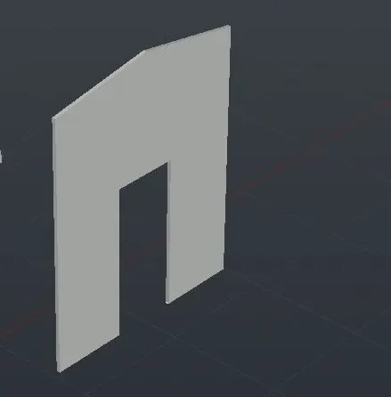
Creating various 3D Models like Furniture, Footing, Girder, Column drop with panel and Gable Wall in AutoCad
1) AIM:- To create a 3D Furniture element as shown in the Figure.
procedure :-
- open cad file and make sure unit is in inches. change the settings to 3D modelling.
- take top view and draw a line of 2" in vertical direction, 3" in horizontal direction and 2" in vertical direction .
- offset the lines by 2" inwards and close the lines.
- type region and select the area drawn. select extrude option and select the area .
- give the extrude height as 2'6"
- take the recatngle option and draw on the top of the extruded figure.make it into a region and extrude the rectangle by 2" downwards.
- take union option and select the two figures to make it into a single figure.
- the resulting figure is given as below.
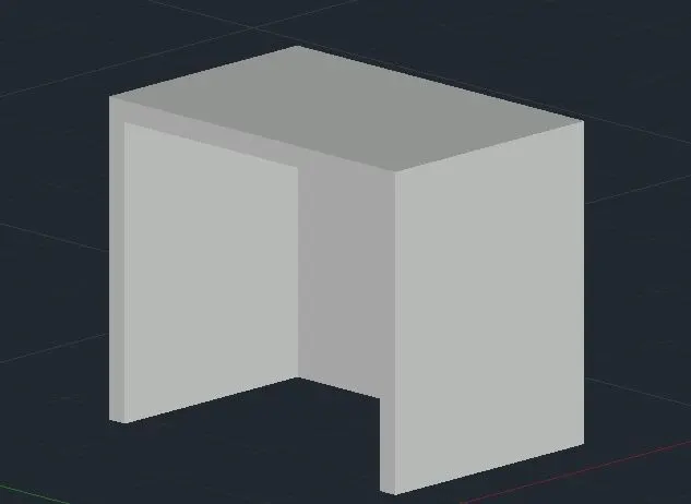
2) AIM:- To create the 3d Model of an Isolated footing as shown in Figure
procedure :-
- open cad file and make sure unit is in inches. change the settings to 3D modelling.
- take top view and draw a square of size 4'x4' . draw another square of size 1'x1' at its centre .change the view to 3D view.
- copy the 4'x4' square to 6". move the smaller square to a height of 2'. take loft option and select the smalle square and the larger square
- now using region option, make the lower square into region and using extrude option, extrude the square by a height of 6".
- using union option , select the two figures so that it is made into a single figure.
- the resulting figure is as given below.
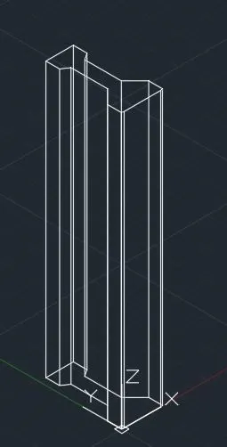
3) AIM:- To create the 3D view of the AASTHO Type Girder.
procedure :-
- open cad file and make sure unit is in inches. change the settings to 3D modelling.
- take top view and draw the plan of the cross section of AASTHO girder.
- using region option select plan drawn and make it into a region.
- using extrude option, extrud ethe region to the required height
- the resulting drawing is a s given below
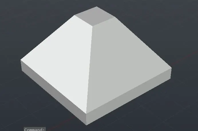
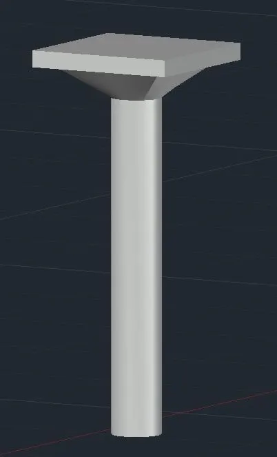
4) AIM:- To create the 3D view of the AASTHO Type Girder.
procedure :-
- open cad file and make sure unit is in inches. change the settings to 3D modelling.
- take top view and draw square of 4'6" and a second square of 3'6" in the middle of the first square.
- draw a circlr of diameter 1'6" and place it in the middle of the smaller square.
- move the rectangle upto a height of 11'6". move the smaller square uoto a height of 11' and circle to a height of 10'.
- using region option, make the larger square into a region and extrude it down a height of 6"
- using loft option, select the smaller square and circle and press enter.
- make a circle of the same diameter and using region and extrude option, extrude it to a height required.
- move this extruded cylinder and place it at the centre of the circle
- using union option select the three figures and press enter to make it into a single figure
- the resulting drawing is as shown below.
5) AIM:- To create the 3d model of a wall as shown in Figure. Consider wall thickness as 9
procedure :-
- open cad file and make sure unit is in inches. change the settings to 3D modelling.
- take the top view and draw a rectangle of thickness 9" and length 10'. draw a smaller for the door.
- take region option and make the rectangle drawn for the door into a region and extrude it to a height of 7'.
- take front view and draw the rest of the elevation of teh house and make it into a region.
- extrude this region by 9".
- taking option subsrtact, select the drawing that has to remain, press enter and then the rectangle extruded for the door and press enter.
- the resulting figure is as given below.