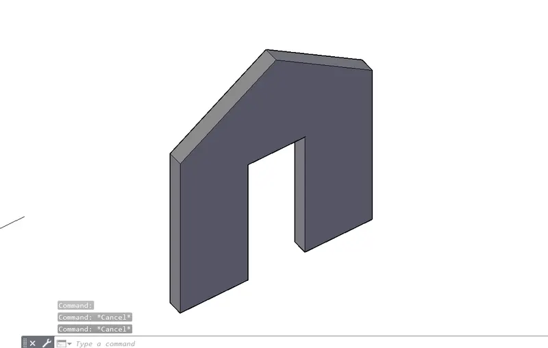
Creating various 3D Models like Furniture, Footing, Girder, Column drop with panel and Gable Wall in AutoCad
QUESTION NO -01
ANSWER :
AIM: IN THIS QUESTION WE HAVE TO DRAW THE 3D FURNITURE ELEMENT SHOWN IN THE FIGURE: IF ANY DIMENSIONS ARE MISSING WE CAN ASSUME.
INTRODUCTION: IN THIS CHALLENGE WE HAVE TO DRAW THE 3D MODELLING OG GIVEN FURNITURE WITH THE USE OF AUTOCAD 3D
START THIS DRAWING FIRST OF ALL WE HAVE TO DO SOME SETTINGS ACCORDING TO THE DRAWING -
SOFTWARE SETTINGS
DRAWING-LINK:
https://web.autocad.com/acad/me/sid/shares/drawings/6591ada6-002c-43e1-816b-94a1375b6e14/editor
SETTINGS - OPEN AUTOCAD
- SET DEFAULT SETTINGS - IMPERIAL UNIT (FEET AND INCHES )
- SELECT A TEMPLATE - ACCORDING TO DRAWINGS
- SELECT A WIZARD - ADVANCED SETUP
- UNITS - DECIMAL
- ANGLE - DECIMAL DEGREES
- ANGLE MEASURE - ACCORDING TO THE PLAN
- ANGLE DIRECTION - COUNTER-CLOCKWISE
- AREA - ACCORDING TO THE PLAN
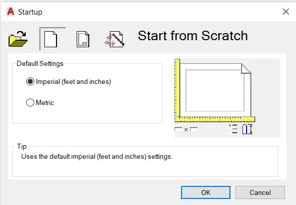
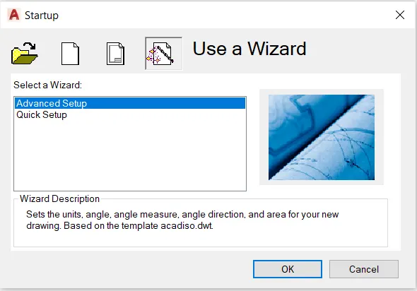
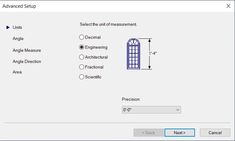
After this enter "D" for the dimension unit and set primary unit ARCHITECTURAL set precision 0'-0"
GO TO WORKSPACE SWITCHING - SELECT 3D MODELLING 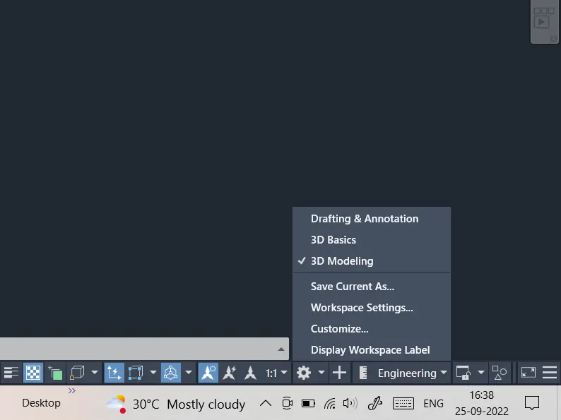
MODES -
- GRID ON BY F7 'CONTROL+G'
- USE ORTHO MODE FOR STRAIGHT 90-DEGREE ACCORDING TO NEED(F8)
- ON POLAR TRACKING (F10) SET ANGLE (15,30,45)
- OBJET SNAP TRACKING (F11)
- OBJECT SNAP (F3)
- TRANPARANCY ON WHEN YOU NEED
OTHER DATA:
- HEIGHT OF THE FURNITURE: 2'-6"
- LENGHT OF THE FURNITURE : 3'
- WIDTH OF THE FURNITURE WOOD: 2"
- ASSUMED WIDTH OF FURNITURE: 2'
PROCEDURE: TO DRAW THE LAYOUT PLAN WE FOLLOW THE FOLLOWING STEPS: -
PROCEDURE: TO DRAW THE LAYOUT PLAN WE FOLLOW THE FOLLOWING STEPS: -
STEP-1
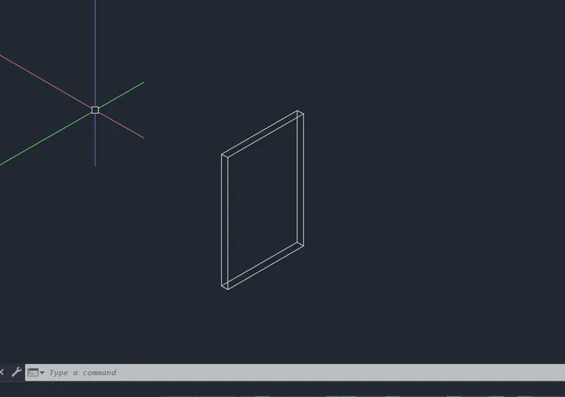
- To draw the furniture first of all we have to take the box command
- And draw the box with a length of 2' width 2" and height of 2'-6".
STEP-2
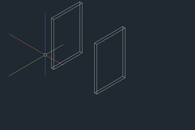
- Now Take copy command copy this object and put it with a distance of 3' width same plan.
STEP-3
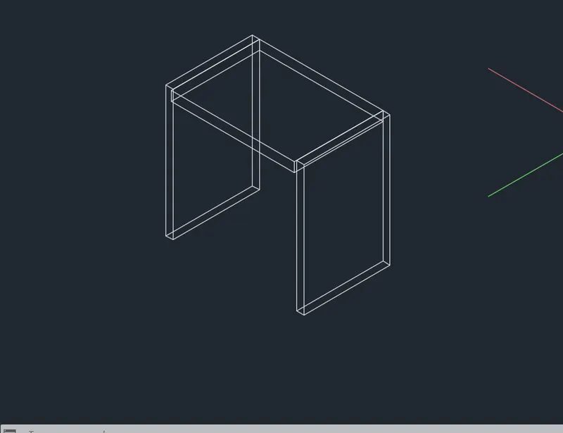
- Again Take the box command and draw the box with a horizontal plane.
- And start this width 2' length = 3' and height of upper wood is 2"
STEP-4
Now Go to again box command and draw a box-back side in the furniture width 2" width.
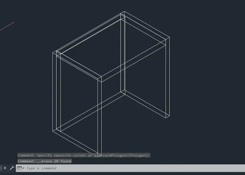
STEP-5
VISUAL STYLE CONTROL
- Go to visual style control and select the shade option.
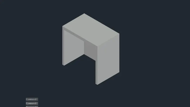
STEP-6
- GO to layout command and set the different layout.
HIDDEN
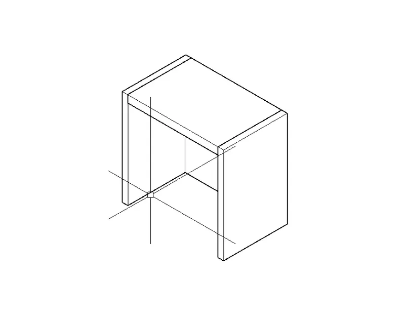
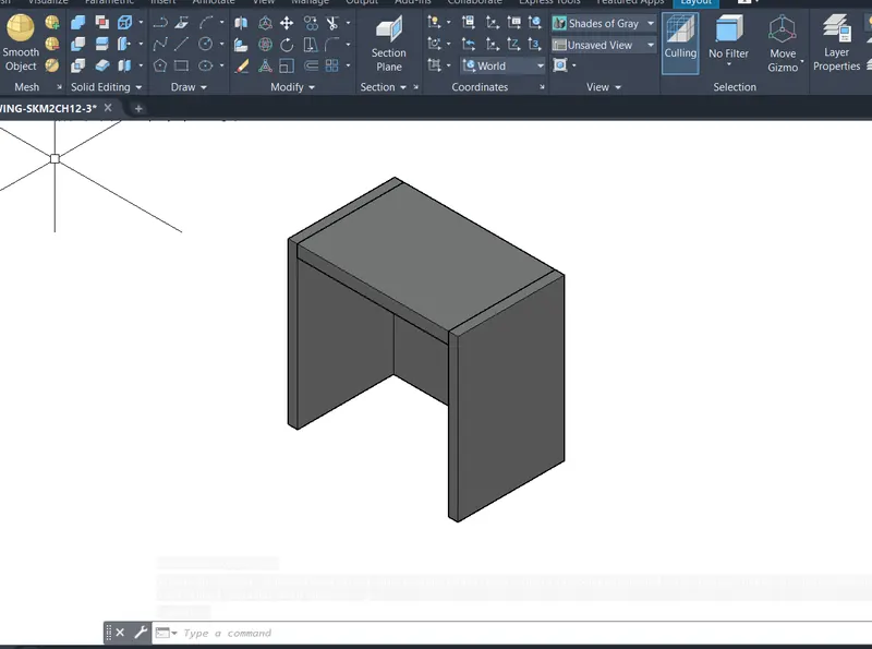
RESULT:THE GIVEN DRAWING ARE COMPLETED WITH THE GIVEN FIGUE .AFTER MAKING THE DRAWING FINAL DRAWING SCREENSHOTS ARE ATTACHED WITH RESULTENT DRAWING .THE LINK OF THE DRAWING OF AUTOCAD IS ALSO ATTACHED FOR REFRENCE.
AUTOCADE DRAWING FILE LINK:
https://web.autocad.com/acad/me/sid/shares/drawings/6591ada6-002c-43e1-816b-94a1375b6e14/editor
https://web.autocad.com/acad/me/sid/shares/drawings/6591ada6-002c-43e1-816b-94a1375b6e14/editor
RESULTANT DRAWING:
QUESTION NO -02
ANSWER :
AIM: CREATE THE 3DMODEL OF AN ISOLATED FOOTINGS A SHOWN IN FIGURE.
INTRODUCTION: IN THIS CHALLENGE WE HAVE TO DRAW THE 3D MODELLING OF ISOLATED FOOTING WITH THE USE OF AUTOCAD 3D COMMANDS.
START THIS DRAWING FIRST OF ALL WE HAVE TO DO SOME SETTINGS ACCORDING TO THE DRAWING -
SOFTWARE SETTINGS
DRAWING-LINL:
https://web.autocad.com/acad/me/sid/shares/drawings/26916e47-41cd-42d7-916a-ef5b42b1859c/editor
SETTINGS - OPEN AUTOCAD
- SET DEFAULT SETTINGS - IMPERIAL UNIT ( FEET AND INCHES )
- SELECT A TEMPLATE - ACCORDING TO DRAWINGS
- SELECT A WIZARD - ADVANCED SETUP
- UNITS - DECIMAL
- ANGLE - DECIMAL DEGREES
- ANGLE MEASURE - ACCORDING TO THE PLAN
- ANGLE DIRECTION - COUNTER-CLOCKWISE
- AREA - ACCORDING TO THE PLAN
After this enter "D" for The dimension unit and set primary unit ARCHITECTURAL set precision 0'-0"
GO TO WORKSPACE SWITCHING - SELECT 3D MODELLING
MODES -
- GRID ON BY F7 'CONTROL+G'
- USE ORTHO MODE FOR STRAIGHT 90-DEGREE ACCORDING TO THE NEED(F8)
- ON POLAR TRACKING (F10) SET ANGLE (15,30,45)
- OBJET SNAP TRACKING (F11)
- OBJECT SNAP (F3)
- TRANPARANCY ON WHEN YOU NEED
PROCEDURE: TO DRAW THE LAYOUT PLAN WE FOLLOW THE FOLLOWING STEPS: -
STEP-1
- To draw this pyramid take rec command with a thickness of 6"
- Put the length of rectangle 3' and width of rectangle 3'
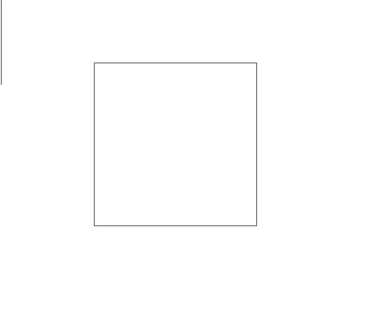
STEP-2
- now go to navigation Part and set navigation.
- Again take rec command without thickness
- put the length and width 1'x1'
- it is drawn with the same geometric centre as the previous rectangle.
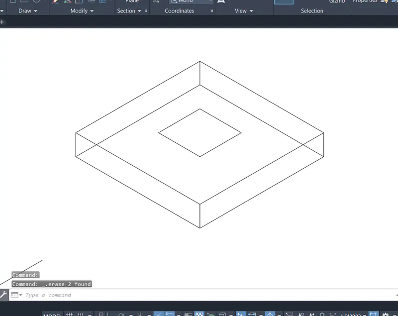
STEP-3
- Now select the internal rectangle and move this in the Z direction width of 2'-6"
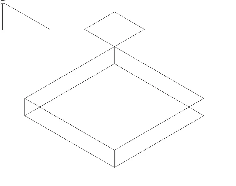
STEP-4
- Width the help of line command connect the corner point of the both rectangle as shown in the figure.
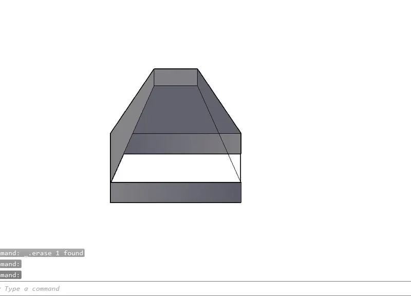
STEP-5
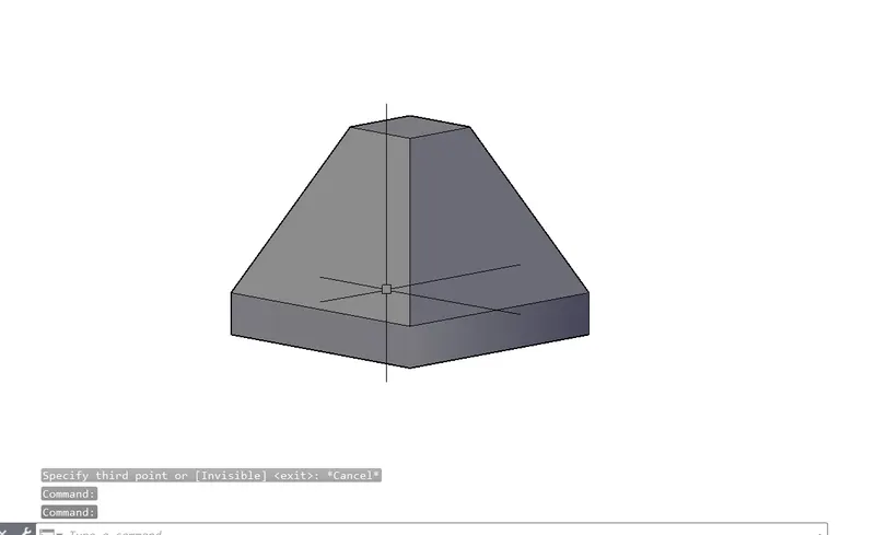
3DFACE OF THE OBJECT
- Now start the 3dface process.
- For this enter 3DFACE in the command bar and press enter
- select the face point of the object and select four points to create one face.
- All the faces are done with the 3DFACE command.
STEP-6
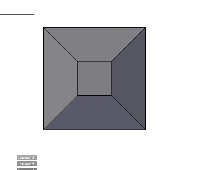
TOP VIEW OF THE OBJECCT
RESULT:THE GIVEN DRAWING ARE COMPLETED WITH THE GIVEN FIGUE .AFTER MAKING THE DRAWING FINAL DRAWING SCREENSHOTS ARE ATTACHED WITH RESULTENT DRAWING .THE LINK OF THE DRAWING OF AUTOCAD IS ALSO ATTACHED FOR REFRENCE.
AUTOCADE DRAWING FILE LINK:
https://web.autocad.com/acad/me/sid/shares/drawings/26916e47-41cd-42d7-916a-ef5b42b1859c/editor
https://web.autocad.com/acad/me/sid/shares/drawings/26916e47-41cd-42d7-916a-ef5b42b1859c/editor
RESULTANT DRAWING:
QUESTION NO -03
ANSWER :
AIM:CREATE A 3DVIEW OF THE AASTHO TYPE GIRDER VIEW.
INTRODUCTION: IN THIS CHALLENGE WE HAVE TO DRAW THE 3D MODELLING OF GIRDER WITH HELP OF AUTOCAD 3D COMMANDS.
START THIS DRAWING FIRST OF ALL WE HAVE TO DO SOME SETTINGS ACCORDING TO THE DRAWING -
SOFTWARE SETTINGS
DRAWING-LINK:
https://web.autocad.com/acad/me/sid/shares/drawings/3321c5ae-7e8a-4dd6-836a-db0aecd791f2/editor
SETTINGS - OPEN AUTOCAD
- SET DEFAULT SETTINGS - IMPERIAL UNIT (FEET AND INCHES )
- SELECT A TEMPLATE - ACCORDING TO DRAWINGS
- SELECT A WIZARD - ADVANCED SETUP
- UNITS - DECIMAL
- ANGLE - DECIMAL DEGREES
- ANGLE MEASURE - ACCORDING TO THE PLAN
- ANGLE DIRECTION - COUNTER-CLOCKWISE
- AREA - ACCORDING TO THE PLAN
After this enter "D" for the dimension unit and set primary unit ARCHITECTURAL set precision 0'-0"
GO TO WORKSPACE SWITCHING - SELECT 3D MODELLING
MODES -
- GRID ON BY F7 'CONTROL+G'
- USE ORTHO MODE FOR STRAIGHT 90-DEGREE ACCORDING TO NEED(F8)
- ON POLAR TRACKING (F10) SET ANGLE (15,30,45)
- OBJET SNAP TRACKING (F11)
- OBJECT SNAP (F3)
- TRANPARANCY ON WHEN YOU NEED
PROCEDURE: TO DRAW THE LAYOUT PLAN WE FOLLOW THE FOLLOWING STEPS: -
STEP-1
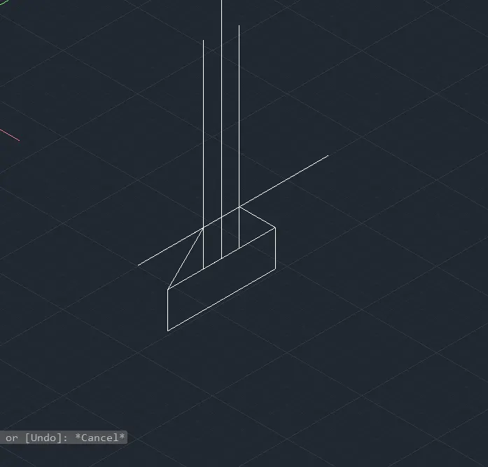
- First of all go to the Y-Z plan and create the front face of the object.
- for this take line of 1'-6" horizontally
- now take 6" vertically on both sides.
- again take 6" on both sides
- take internal 3" on both sides and 1-'6" vertically in the Z direction.
- again take 6" vertically
- and 1' from the top horizontally.
STEP-2
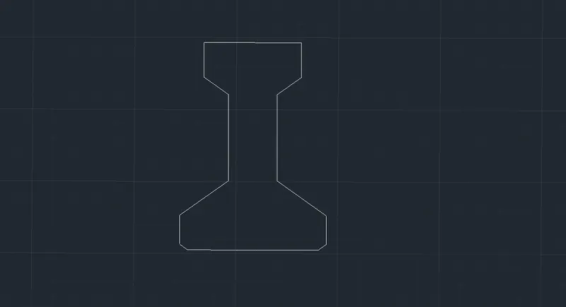
- after this making we get this face.
- Take copy command and copy this object in the -X direction with a distance of 10'
STEP-3
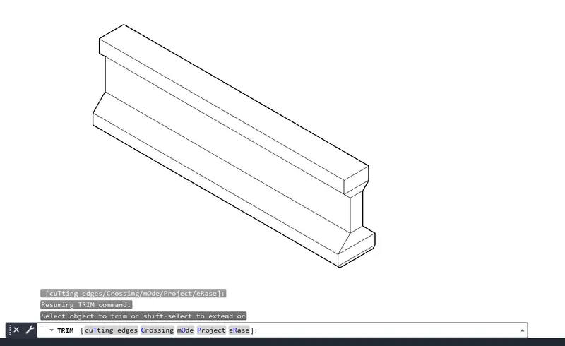
- After taking copy command connect all the corner points of the girder.
- Connect the all point in same the PLANE.
STEP-4
3DFACE OF THE OBJECT
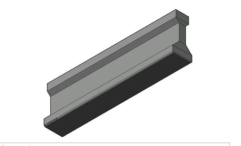
- Now start the 3dface process.
- For this enter 3DFACE in the command bar and press enter
- select the face point of the object and select four points to create one face.
- All the faces are done with the 3DFACE command.
STEP-5
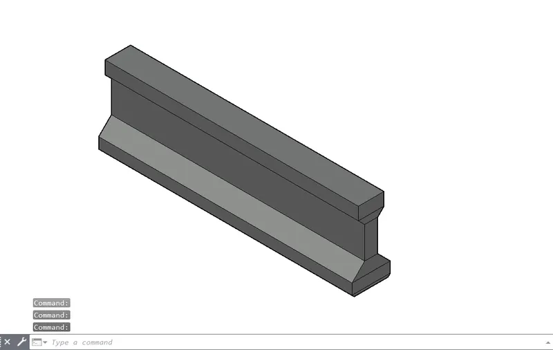
- HIDDEN
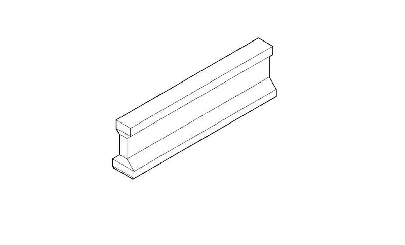
- TOP VIEW:
RESULT:THE GIVEN DRAWING ARE COMPLETED WITH THE GIVEN FIGUE .AFTER MAKING THE DRAWING FINAL DRAWING SCREENSHOTS ARE ATTACHED WITH RESULTENT DRAWING .THE LINK OF THE DRAWING OF AUTOCAD IS ALSO ATTACHED FOR REFRENCE.
AUTOCADE DRAWING FILE LINK:
https://web.autocad.com/acad/me/sid/shares/drawings/3321c5ae-7e8a-4dd6-836a-db0aecd791f2/editor
https://web.autocad.com/acad/me/sid/shares/drawings/3321c5ae-7e8a-4dd6-836a-db0aecd791f2/editor
RESULTANT DRAWING:
QUESTION NO -04
ANSWER :
AIM:CREATE A 3D MODEL OF A DROP COLUMN WITH PANEL AS SHOWN N SECTION AND ISOMETRIC VIEW.
INTRODUCTION: IN THIS CHALLENGE WE HAVE TO DRAW THE 3D MODELLING OF DROP COLUM AND ALOS GIVE THE ISOMETRIC VEIW WITH THE HEKP OF AUTOCAD 3D COMMANDS.
START THIS DRAWING FIRST OF ALL WE HAVE TO DO SOME SETTINGS ACCORDING TO THE DRAWING -
SOFTWARE SETTINGS
DRAWING-LINK:
https://web.autocad.com/acad/me/sid/shares/drawings/de3b1d2b-849c-429d-b545-41a924879984/editor
SETTINGS - OPEN AUTOCAD
- SET DEFAULT SETTINGS - IMPERIAL UNIT (FEET AND INCHES )
- SELECT A TEMPLATE - ACCORDING TO DRAWINGS
- SELECT A WIZARD - ADVANCED SETUP
- UNITS - DECIMAL
- ANGLE - DECIMAL DEGREES
- ANGLE MEASURE - ACCORDING TO THE PLAN
- ANGLE DIRECTION - COUNTER-CLOCKWISE
- AREA - ACCORDING TO THE PLAN
After this enter "D" for the dimension unit and set primary unit ARCHITECTURAL set precision 0'-0"
GO TO WORKSPACE SWITCHING - SELECT 3D MODELLING
MODES -
- GRID ON BY F7 'CONTROL+G'
- USE ORTHO MODE FOR STRAIGHT 90-DEGREE ACCORDING TO NEED(F8)
- ON POLAR TRACKING (F10) SET ANGLE (15,30,45)
- OBJET SNAP TRACKING (F11)
- OBJECT SNAP (F3)
- TRANPARANCY ON WHEN YOU NEED
PROCEDURE: TO DRAW THE LAYOUT PLAN WE FOLLOW THE FOLLOWING STEPS: -
STEP-1
- Now start the to creating the column.
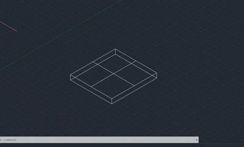
- Take box command and put the dimension the 4'-6' x4'-6" and height of the box the 6".
- Now take line command to give center of the box
- this box is create in the horizontal plan.
STEP-2
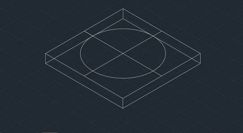
- Now Take circle command to create the circle. with 3"from edges
- Again take circle command and creat circle with Diameter of 1'6"
- now select this and put this vertically 1' from bottom to +z directon.
STEP-3
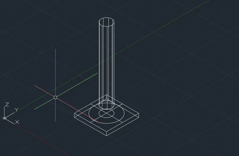
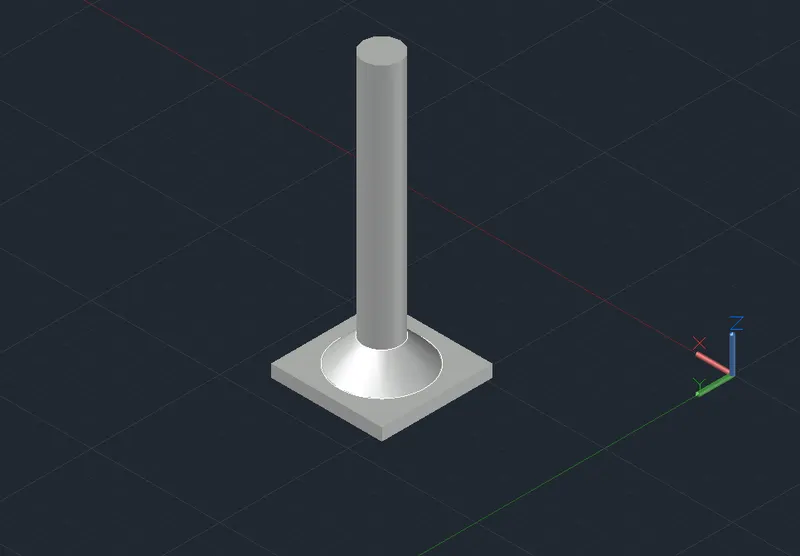
- Now Take pressed full command and press the circle 10' in the Z direction.
- And Take cone command to create the bottom of the column
- create a cone with a diameter of 3'6" and an upper diameter is 1'
STEP-4
DIFFREFNT VIEW:
SHADE:
STEP-5
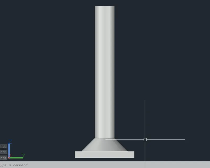
FRONT VIEW:
STEP-6
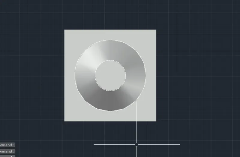
TOP - VIEW:
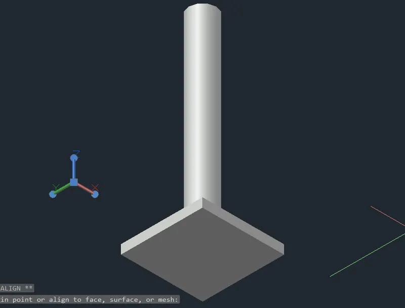
BOTTOM SIDE VIEW:
RESULT:THE GIVEN DRAWING ARE COMPLETED WITH THE GIVEN FIGUE .AFTER MAKING THE DRAWING FINAL DRAWING SCREENSHOTS ARE ATTACHED WITH RESULTENT DRAWING .THE LINK OF THE DRAWING OF AUTOCAD IS ALSO ATTACHED FOR REFRENCE.
AUTOCADE DRAWING FILE LINK:
https://web.autocad.com/acad/me/sid/shares/drawings/de3b1d2b-849c-429d-b545-41a924879984/editor
https://web.autocad.com/acad/me/sid/shares/drawings/de3b1d2b-849c-429d-b545-41a924879984/editor
RESULTANT DRAWING:
QUESTION NO -05
ANSWER :
AIM:CREATE THE 3D MODEL OF A WALL AS SHOWN IN FIGURE: CONSIDER WALL THICKNESS AS 9".
INTRODUCTION: IN THIS CHALLENGE WE HAVE TO DRAW THE 3D MODELLING OF GIVEN WALL WITH THE THICKNESS OF 9" IN AUTOCAD 3D WITH USE OF 3D COMMANDS
START THIS DRAWING FIRST OF ALL WE HAVE TO DO SOME SETTINGS ACCORDING TO THE DRAWING -
SOFTWARE SETTINGS
DRAWING-LINK:
SETTINGS - OPEN AUTOCAD
- SET DEFAULT SETTINGS - IMPERIAL UNIT (FEAET AND INCHES )
- SELECT A TEMPLATE - ACCORDING TO DRAWINGS
- SELECT A WIZARD - ADVANCED SETUP
- UNITS - DECIMAL
- ANGLE - DECIMAL DEGREES
- ANGLE MEASURE - ACCORDING TO THE PLAN
- ANGLE DIRECTION - COUNTER-CLOCKWISE
- AREA - ACCORDING TO THE PLAN
After this enter "D" for the dimension unit and set primary unit ARCHITECTURAL set precision 0'-0"
GO TO WORKSPACE SWITCHING - SELECT 3D MODELLING
MODES -
- GRID ON BY F7 'CONTROL+G'
- USE ORTHO MODE FOR STRAIGHT 90-DEGREE ACCORDING TO THE NEED(F8)
- ON POLAR TRACKING (F10) SET ANGLE (15,30,45)
- OBJET SNAP TRACKING (F11)
- OBJECT SNAP (F3)
- TRANPARANCY ON WHEN YOU NEED
OTHER DATA:
- HEIGHT OF THE DOOR : 7'
- WIDTH OF THE WALL : 9"
PROCEDURE: TO DRAW THE LAYOUT PLAN WE FOLLOW THE FOLLOWING STEPS: -
STEP-1
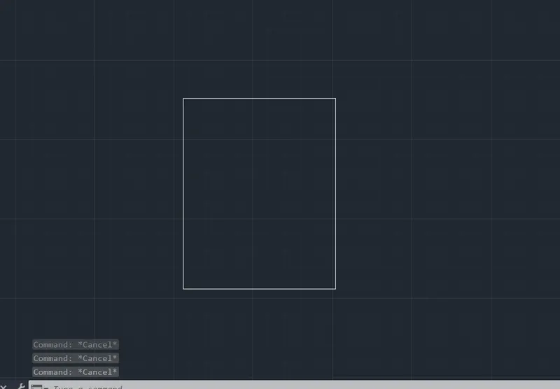
VIEW-CONTROLS:
- To draw the wall go to view control and put the front view
- Take rectangle command draw rectangle dimension of 10'x12'6"
- for wall
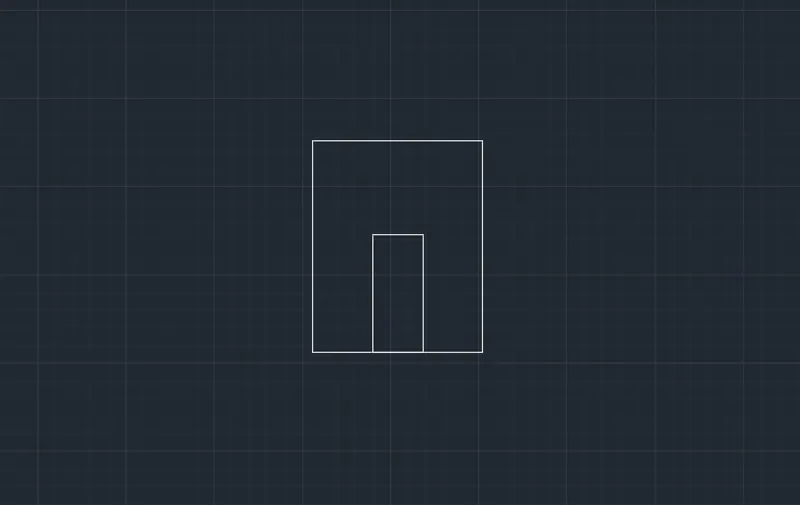
STEP-2
- Again take the rectangle command and draw the rectangle for door with 3'width and 7' of height.
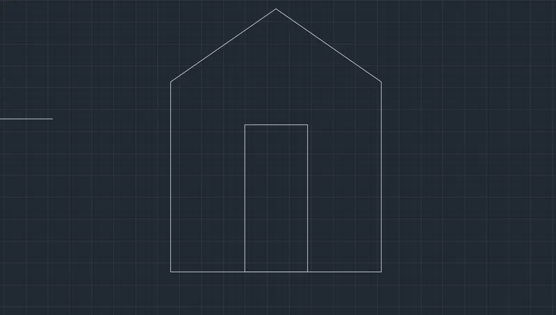
STEP-3
- Now we get this .go to press pull command and select wall object and press it in the upper direction with a thickness of 9"
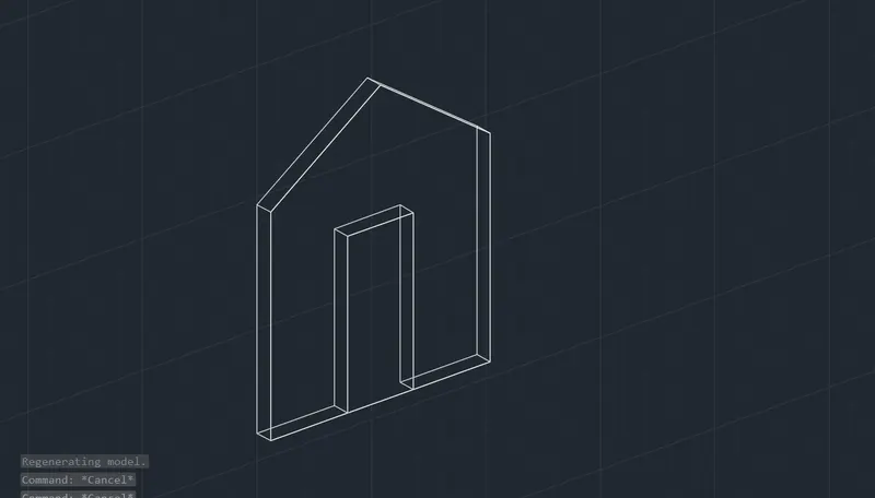
STEP-4
- Now set the view isometric.
STEP-5
- Go to shade command and shade this object or you can go with realistic or conceptual.
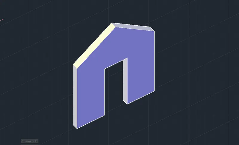
RESULT:THE GIVEN DRAWING ARE COMPLETED WITH THE GIVEN FIGUE .AFTER MAKING THE DRAWING FINAL DRAWING SCREENSHOTS ARE ATTACHED WITH RESULTENT DRAWING .THE LINK OF THE DRAWING OF AUTOCAD IS ALSO ATTACHED FOR REFRENCE.
AUTOCADE DRAWING FILE LINK:
https://web.autocad.com/acad/me/sid/shares/drawings/a82de148-e801-403f-a2f2-940bb864d6b6/editor
https://web.autocad.com/acad/me/sid/shares/drawings/a82de148-e801-403f-a2f2-940bb864d6b6/editor
RESULTANT DRAWING: