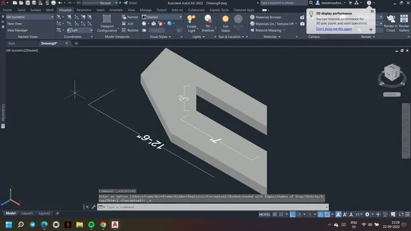
Creating various 3D Models like Furniture, Footing, Girder, Column drop with panel and Gable Wall in AutoCad
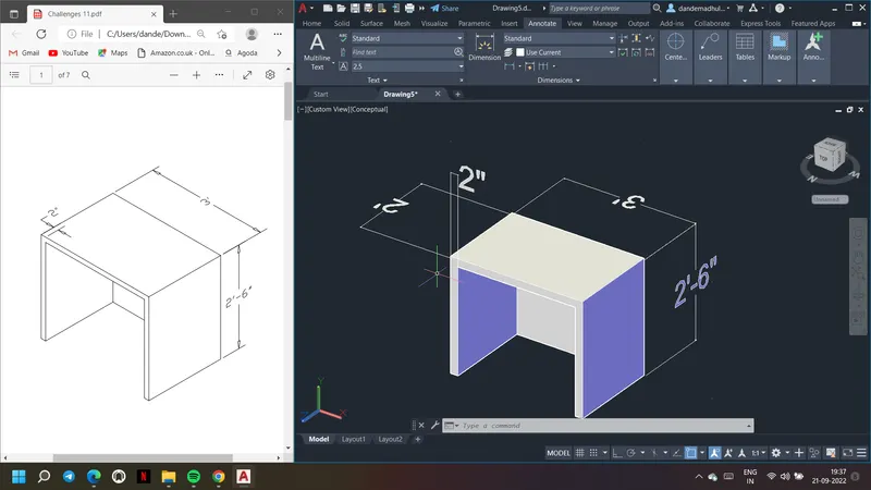
Aim & Introduction: Need to create given 3D furniture element. Dimesnsions are assumed whichever are missing. Solidedit command is used to obtain the given 3D furniture element. Dimlinear is used to insert dimensions, also UCS command is used to shift the axes wherever required for measuring the distances.
Procedure:
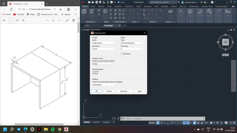
1. First open the new drawing and choose units as engineering by giving units command
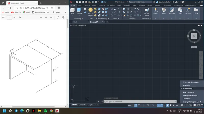
2. Select the 3D Modelling option as shown below
3. First draw a rectangle with dimensions 3' and 2'
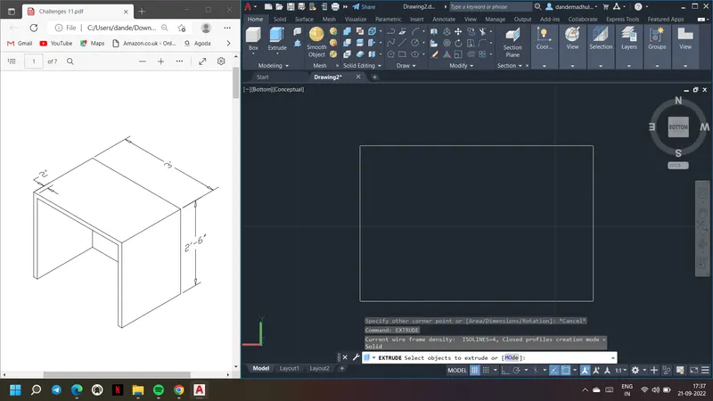
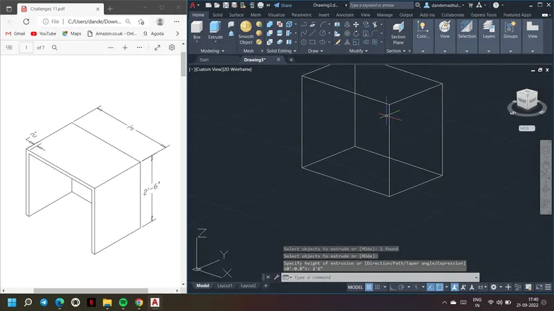
4. Then by using extrude command, select the rectangle and extrude it to height of 2'6"
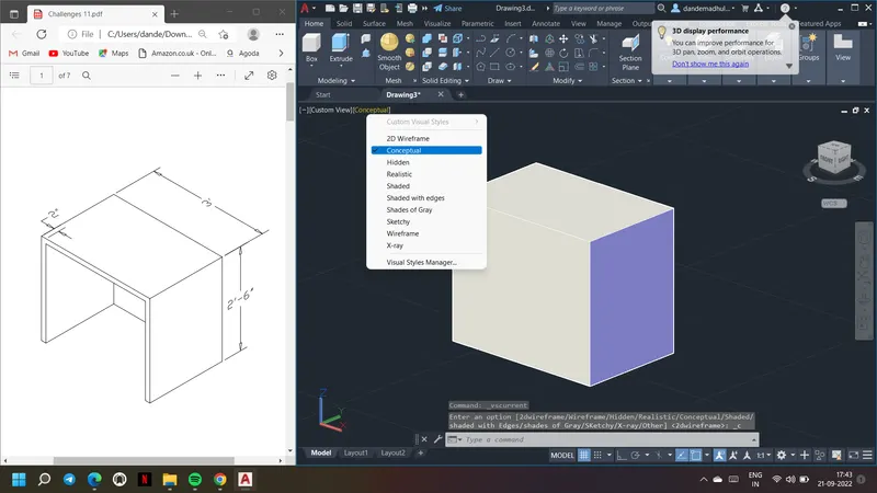
5. Then in visualize we can choose conceptual to get the solid object
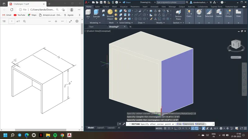
6. Then shift the axis to the corner as shown and draw a rectangle on one face of object
7. Choose first point of rectangle as 0,2,0 and dimensions as 2'8" and 2' 4" to form rectangle with 2" offset as shown
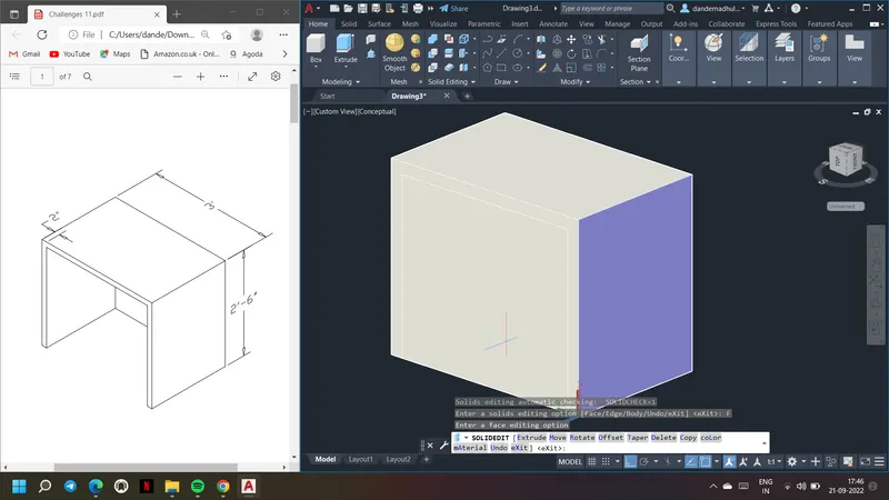
8. Open wireframe view and go to solidedit and then choose body
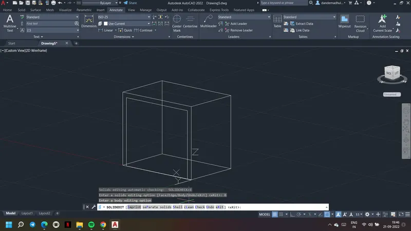
9. In body choose imprint option and select the body and the rectangle drawn to form the surface for the drawn rectangle
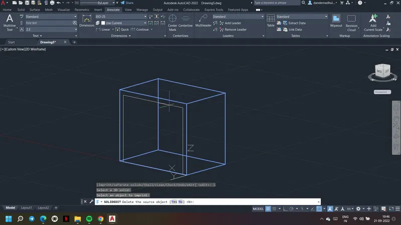
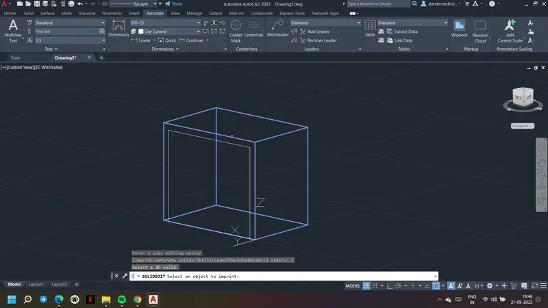
10. Now go to solidedit and choose face option and choose offset mode
11. Then select the surface as shown give offset distance as -1'
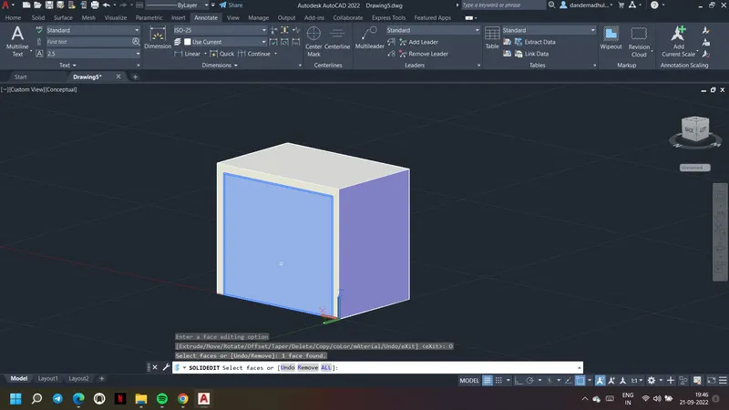
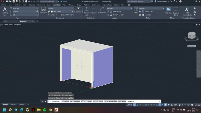
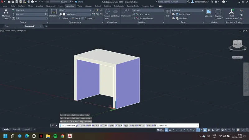
12. Again go to solidedit and choose face and select the surface.
13. Offset it to -11" to form the object as shown
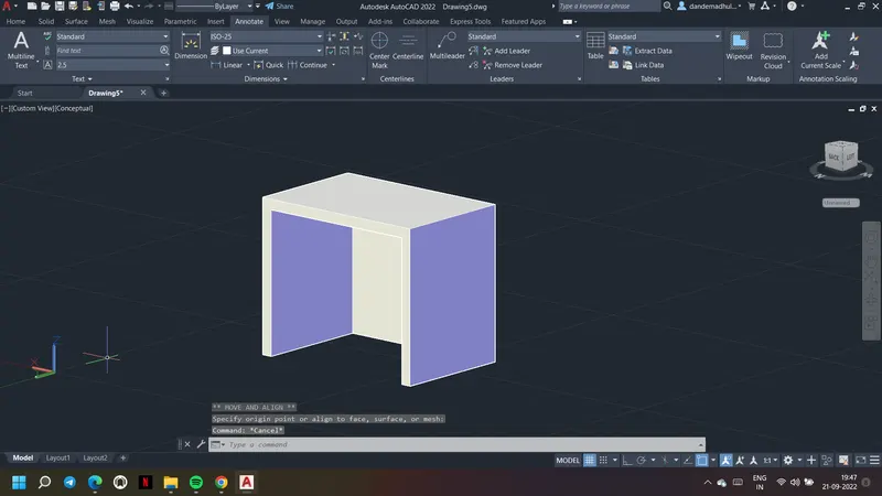
14. Give dimlinear and measure the dimensions
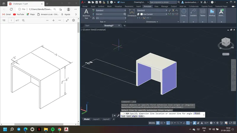
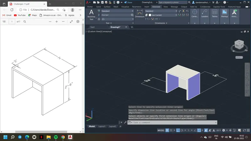
16. Move the dimensions as required using move command
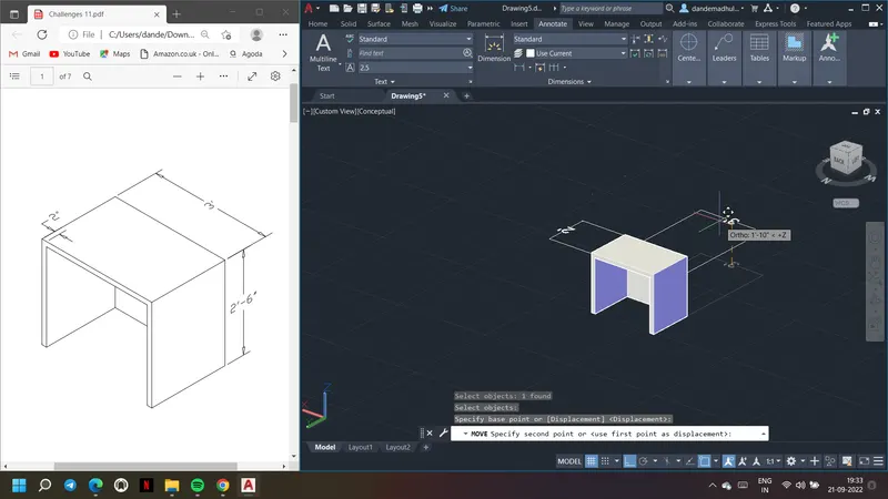
16. Use UCS command to shift the axes accordingly to measure the dimensions
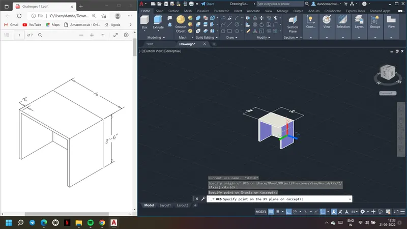
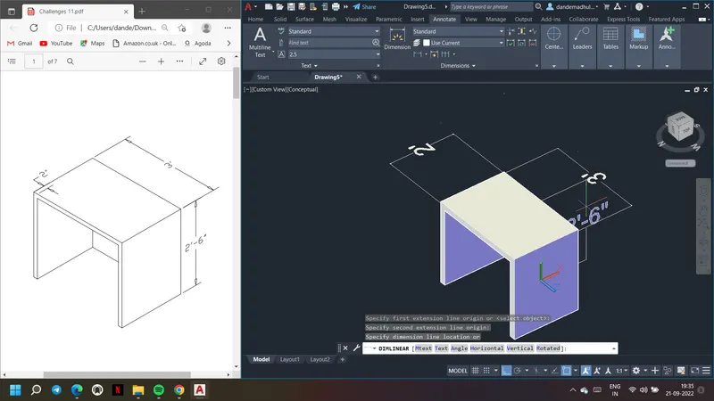
Result: Given 3D furniture element
Aim & Introduction: Creation of 3d Model of an Isolated footing. Pyramid command is used. Solidedit command is used to form the given 3d model of an islated footing.
Procedure:
1. First open the new drawing and choose units as engineering by giving units command
2. Select the 3d modelling
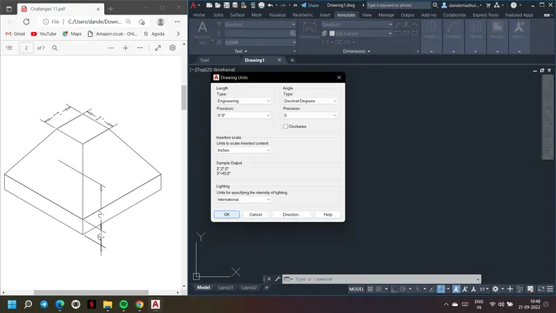
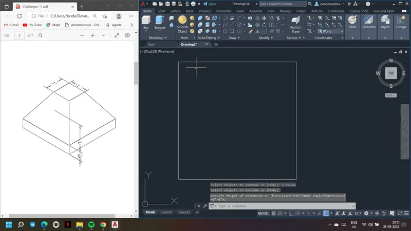
3. Draw a rectangle using rectangle ocmamnd with 2' x 2' dimensions
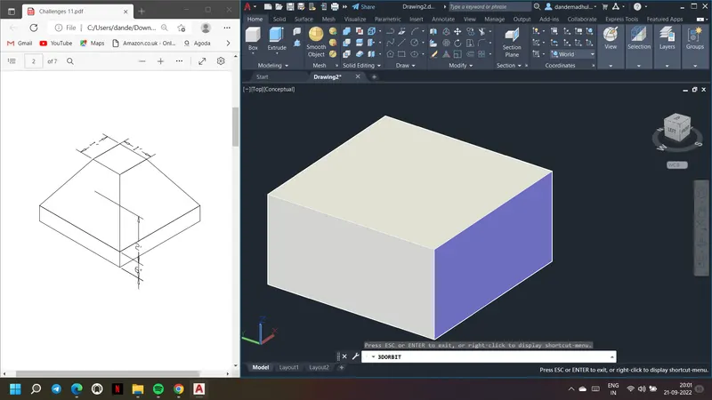
4. Select it and extrude it to 6" height using extrude command
5. Go to conceptual view to form the solid like shown
6. Give pyramid command , using the drawn rectangle as bottom of pyramid
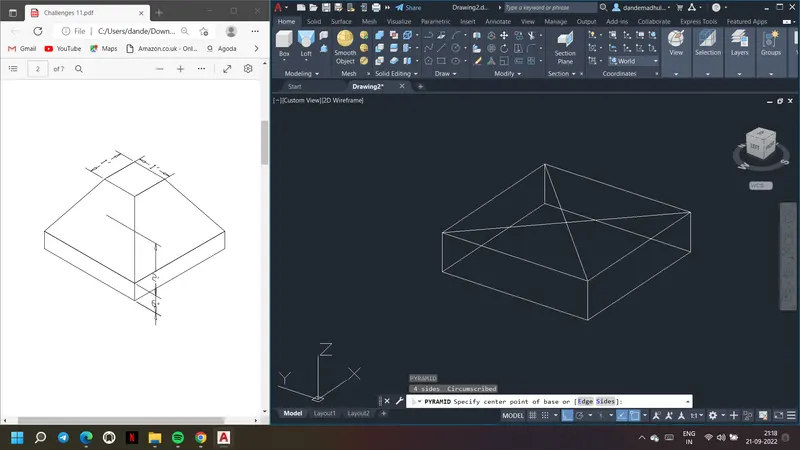
7. Give top radius of pyramid as 1' and height as 2' to form a pyramid as shown below
8. Give command dimlinear and use UCS command to get dimensions of total object
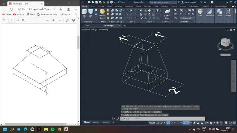
Result: 3D Model of an Isolated footing

Aim & Introduction: Creation of the 3D view of the AASTHO Type Girde. Use solidedit comamnd wherver required. Dimlinear is used to insert the dimensions. Extrude option is used to extrude the object.
Procedure:
1. First open the new drawing and choose units as engineering by giving units command
2. Select the 3d modelling
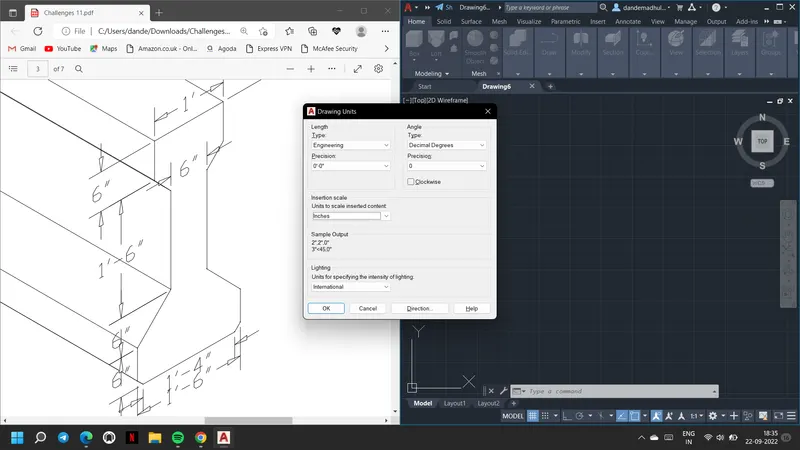
3.Draw a line with line command and 1'6" length and 1'4" length. Use trim option and trim 1' 6" lineafter connected the two lines as shown
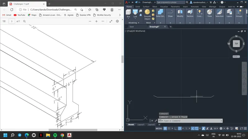
4. Then draw a vertical line of height 1' both sides and draw a inclined line with 45 degree angle at 6" to 6" distance
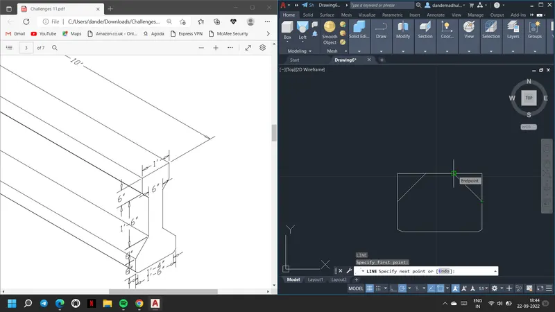
5. Draw a vertical line of 1'6" height and then with angle 45 degree draw line as shown
6. The top line dimension wpuld be 1'. Use trim option to trim the unnecessary lines
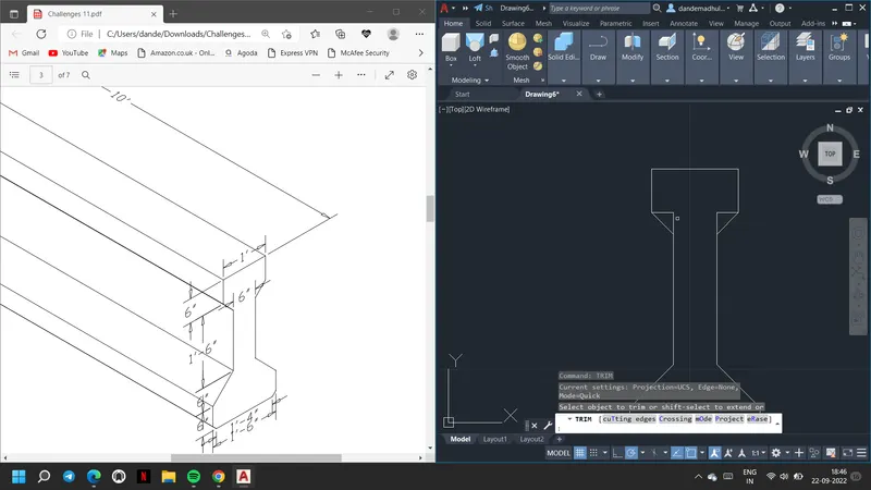
7. The required object is formed then we need to extrude it to form the solid
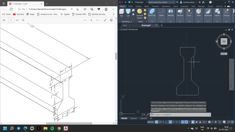
8. Join it to form as one entity and give command extrude and extrude the object.
9. Height of extrusion is 10' as shown below
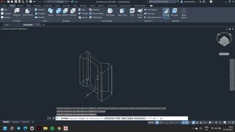
10. Then use the dimlinear and UCS commands to inser the dimensions as shown
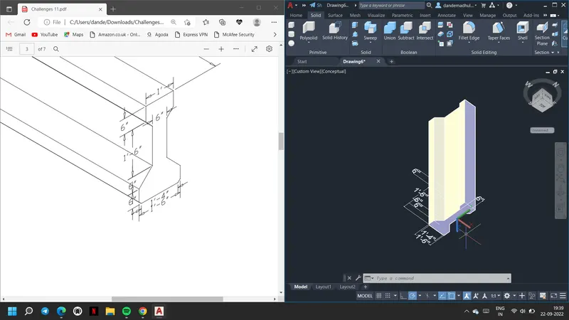
Result: 3D view of the AASTHO Type Girde
Aim & Introduction: Creation of a 3d Model of a rop column with panel in section and also its isometric view. Solidedit command is used wherver required to extrude, imprint the drawn objects. In visualize the views are arranged as required.
Procedure:
1. First open the new drawing and choose units as engineering by giving units command
2. Select the 3d modelling
3. The rectangle is drawn with dimensions 4'6" x 4'6"
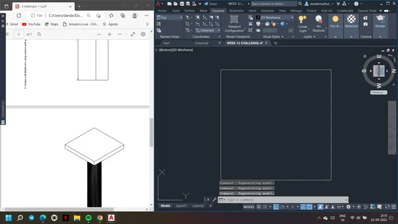
4. A circle of diameter 1'6" is drawn at a height of 1' to the rectangle
5. Then pyramid command is used and using the base of pyramid as 3'6" x 3'6" rectangle pyramid is drawn
6. Top radius and height is choosen as zero as shown
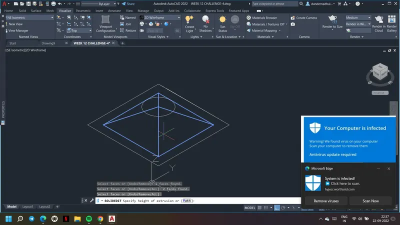

7. Then the initially drawn rectangle is extruded using extrude command with 6" height
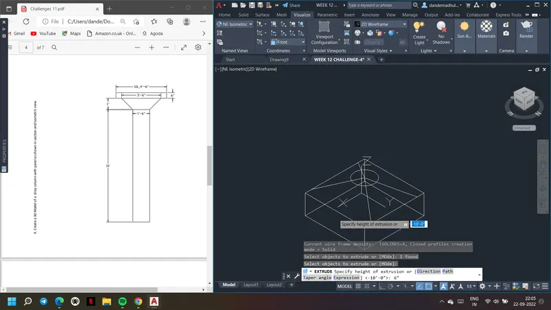
8. Use solidedit command and extrude the pyramid with height being 1'
9. Also extrude the circle with height 10' as given
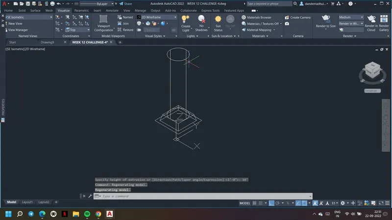
10. The extrusion of the drawn objects is drawn as shown
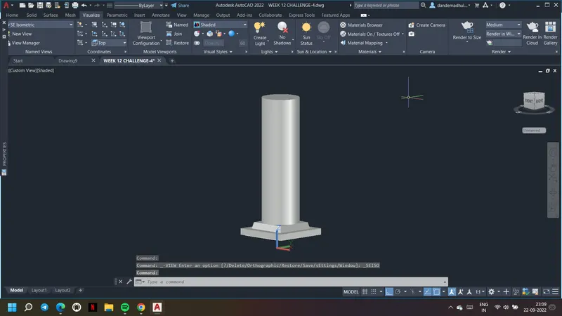
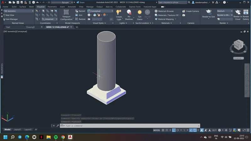
11. Go to isometric view to check the drawn 3d Model of a rop column with panel in isometric view
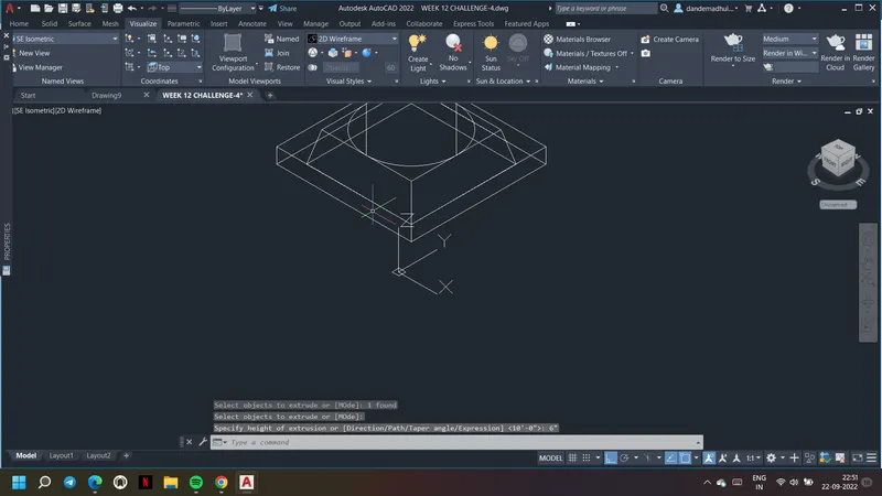
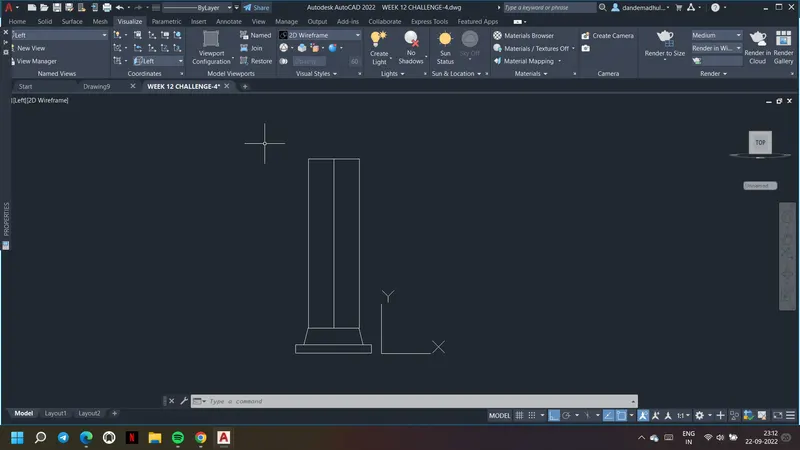
12. Change the view to check the section view of 3d Model of a rop column with panel
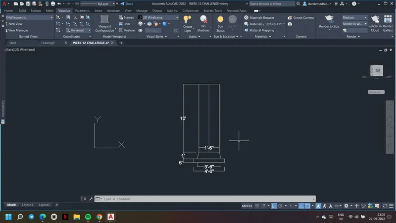
13. Use dimlinear command and UCS commands to insert the dimensions at required places
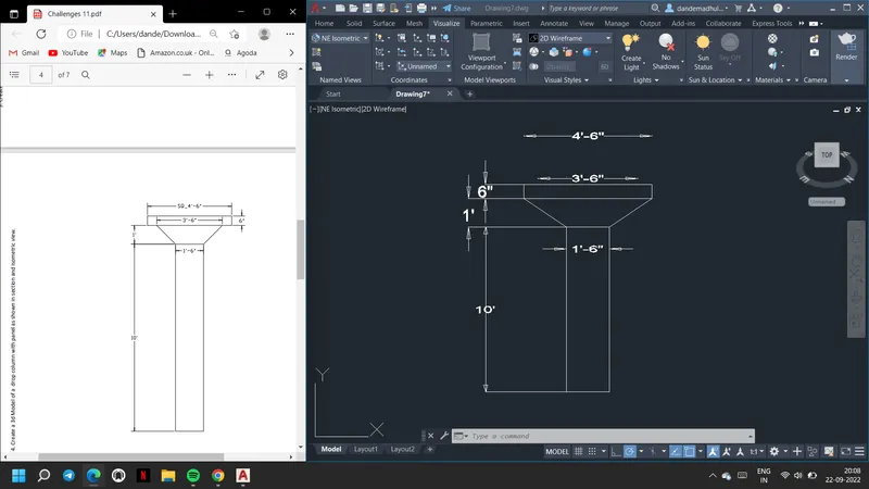
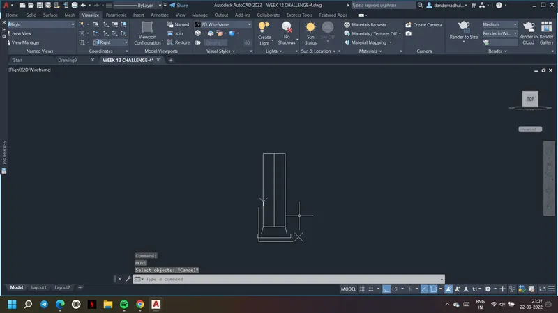
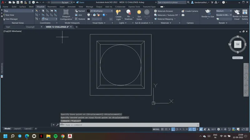
14. The isometric view of 3d Model of a rop column with panel
15. The sectional view of 3d Model of a rop column with panel
16. Can also colour the column as required as shown
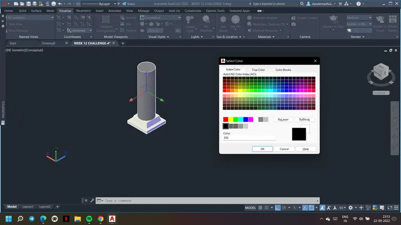
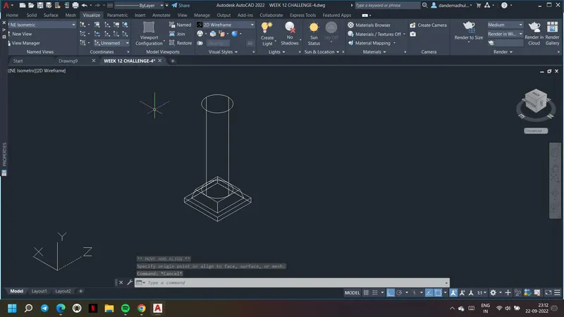
Result:
The sectional view of 3d Model of a rop column with panel
The isometric view of 3d Model of a rop column with panel
Aim & Introduction: Creation of the given 3d model of a wall. The wall thickness is taken as 9”. Soliedit comamnd is used to edit the drawn solid as required. Dimlinear and UCS commands are used to insert dimensions wherever required.
Procedure:
1. First open the new drawing and choose units as engineering by giving units command
2. Select the 3d modelling
3. First draw a vertical line using line command with height 12'6"
4. Draw a horizontal line of length 10' as shown
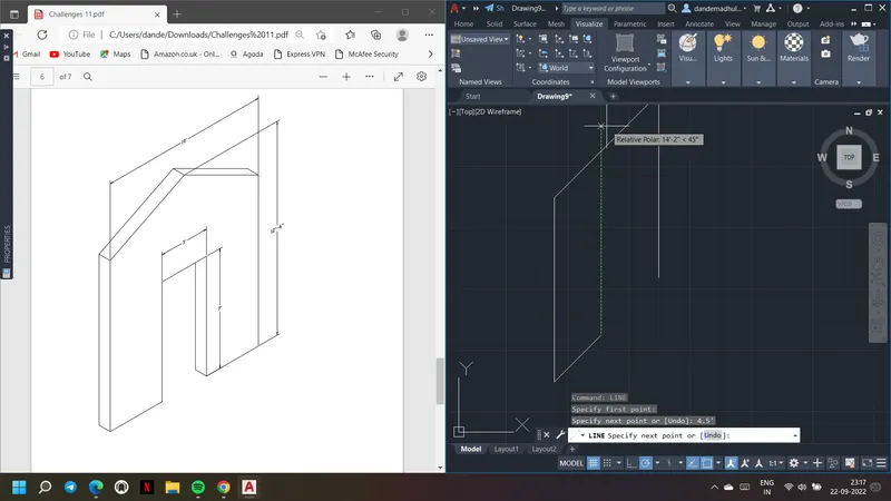
5. Taking 4.5' as length drawn the bottom line and leave 3' distance for the door
6. Draw door with height 7' with line command as shown
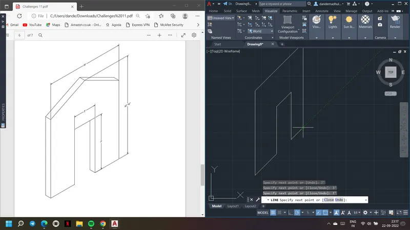
7. Taking top line mid point as center draw the inclined lines as shown. Take the wall height as 9'6" to form obkect as shown
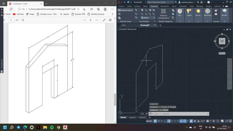
8. Use join or group command and make the object as an entity
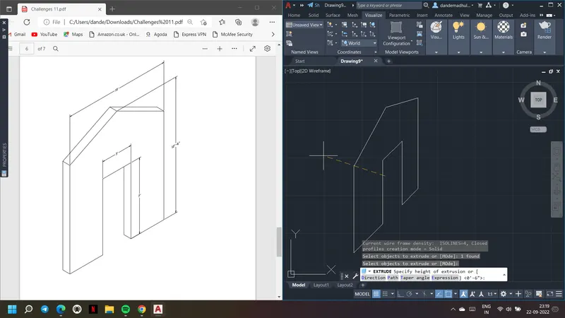
9. Use solidedit command and extrude option to extrude the object with 9" thickness
10. Use dimlinear and UCS commands to insert the dimensions wherever required as shown/
11. Move the dimensions if required using move command
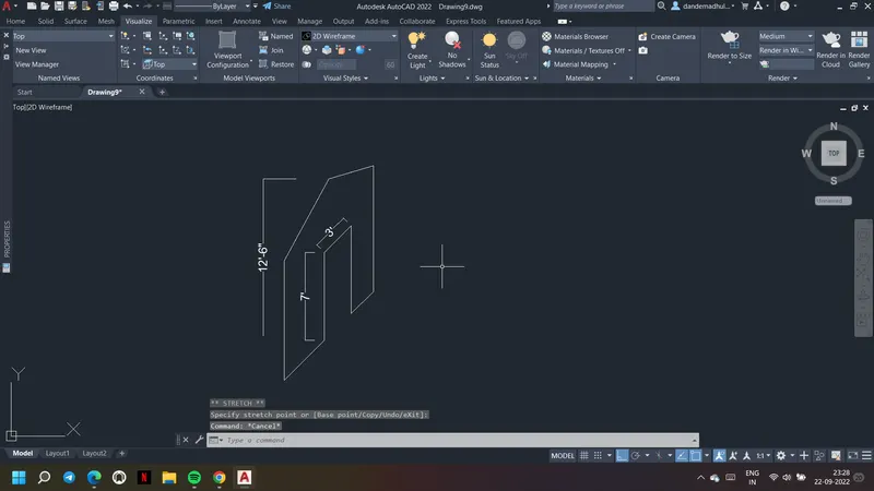
12. Chnage the view in visualization if required for better view and go to conceptual or shaded view to get solid object
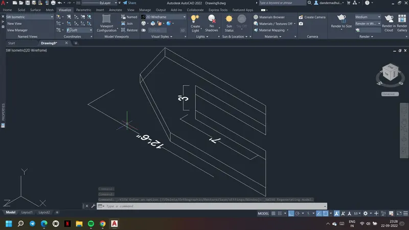
Result: 3D Model of given wall