Creating various 3D Models like Furniture, Footing, Girder, Column drop with panel and Gable Wall in AutoCad
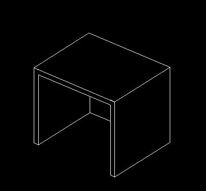
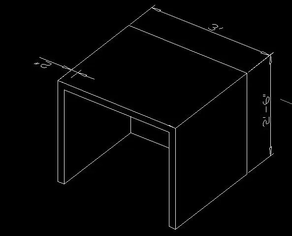
Aim: To Create a 3D Furniture element .
Software that i used : ATOCAD
Yools that i have used :
box
trim
line
rectangle
extrude
procedure:
go to 3d modelling workspace.
put the visual style in the 2d wireframe.
Take box specify the length as 3' , width as 2'6" and height as 2'6".
put ucs in the front face .
take line command draw the line with offset of 2" from top and sides.
take rectangle command make that 2"line in to rectangle.
make that rectangle in to region by using reg command.
go to extrude command extrude the rectangle inside with 2'4".
take subtract tool first select the source and next select remove solid.(2" )
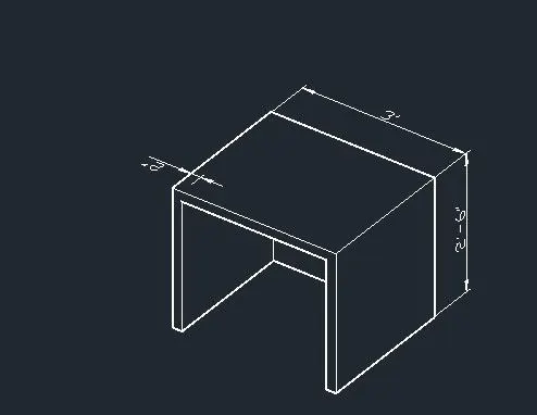
provide dimensions to it.
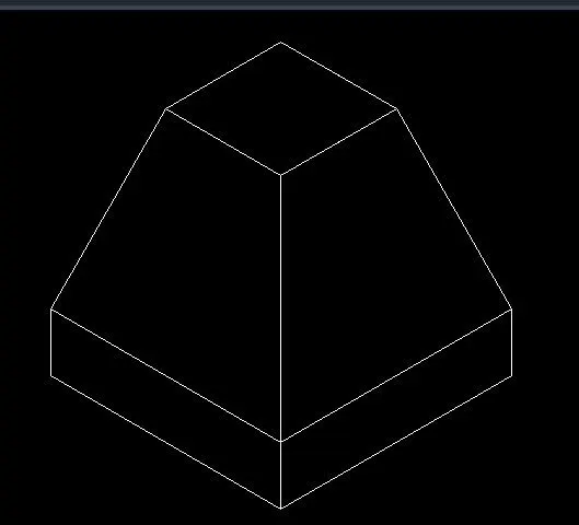
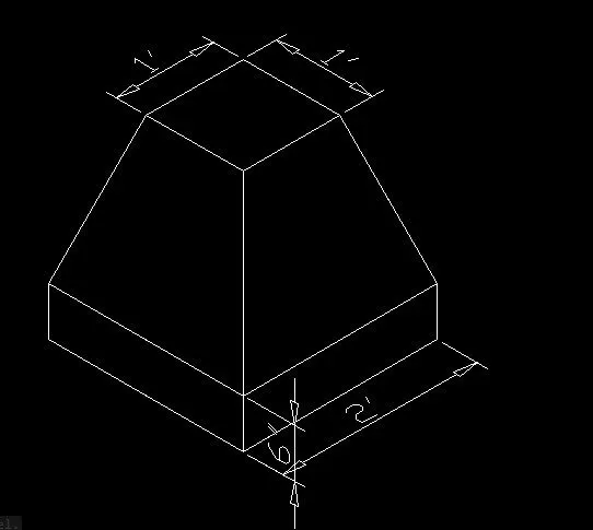
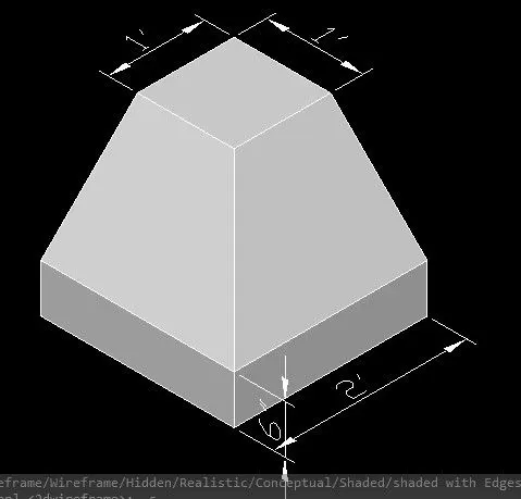
AIM: To Create the 3d Model of an Isolated footing
tools that i have used
rectangle
move
3dorbit
3dface
offset.
procedure:
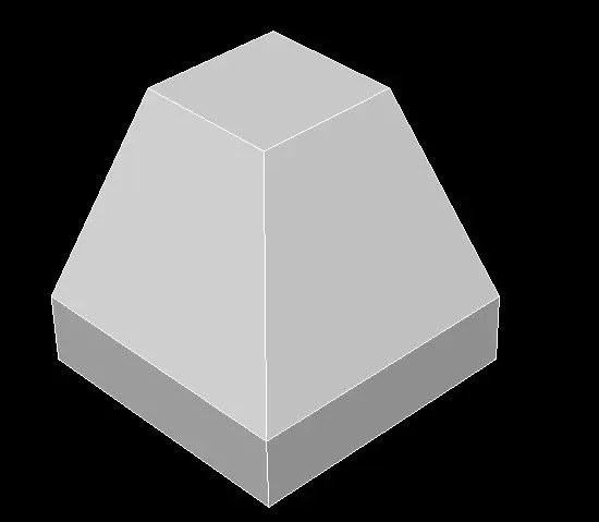
draw rectangle with dimension 2'x2'
take offset command 6" inside the rectangle.
take move command drag the 1' rectangle in z-direction with elevation of 2'
copy the 2' rectangle replica has to place in z-direction with distance of 6".
connect the all corner using line commnad.
assign the surface to the each face .
with the help of 3dorbit and 3d face command surface is provided to that geometry.
dimensions are provided to it.
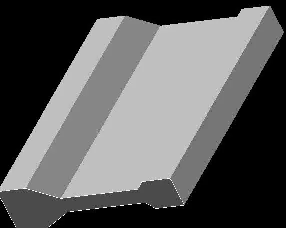
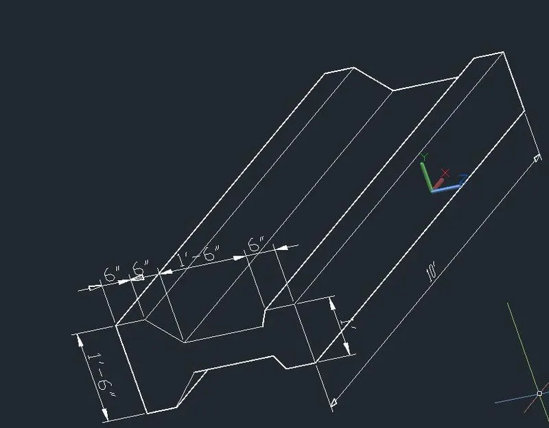
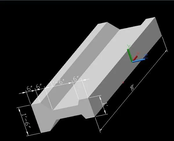
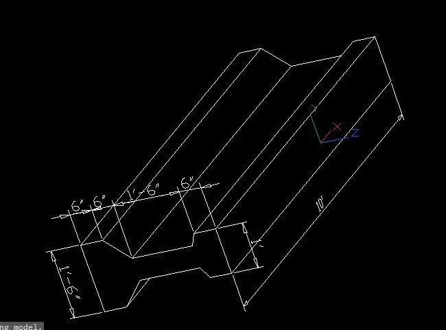
Aim:TO Create the 3D view of the AASTHO Type Girder.
tools i used
line
offset
trim
sweep
mirror
procedure:
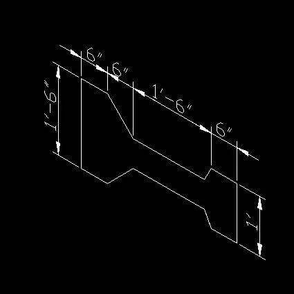
draw a line 1'6".
at the initial end point of the line take a reference draw the vertical line with distance 6"
take midpoint as reference draw the horizontal line with offset 3" top with length of 1'6".
join the 6"line and 1'6" line form inclined line.
draw the line 3' length line midpoint as reference .
draw the vertical line with height of 6" at the 3" line endpoint as reference.
draw the 6" line with respect to x-axis .
join the 6" line and 1'6" line .
take mirror command reflect the top portion to down side 1'6" midpoint as refernce.
draw the line
specify the point as the end of 1".
specify another point as 10'<odegree<45 degree.
take boundary make geometry in to region.
switch shaded visual style.
take sweep command select the object to sweep.
select the path line as that line.
it sweep the object along that line with uniform cross section.
another method
go to extrude command select the geometry.
select the direction option and specify first point as inclined line intial endpoint and second point as final end point.
put the ucs in the front face provided the dimensions to it.
Aim: To Create a 3d Model of a drop column with panel .
tools i used
line
offset
trim
ruled surface
region
extrude
rectangle
procedure
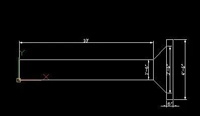
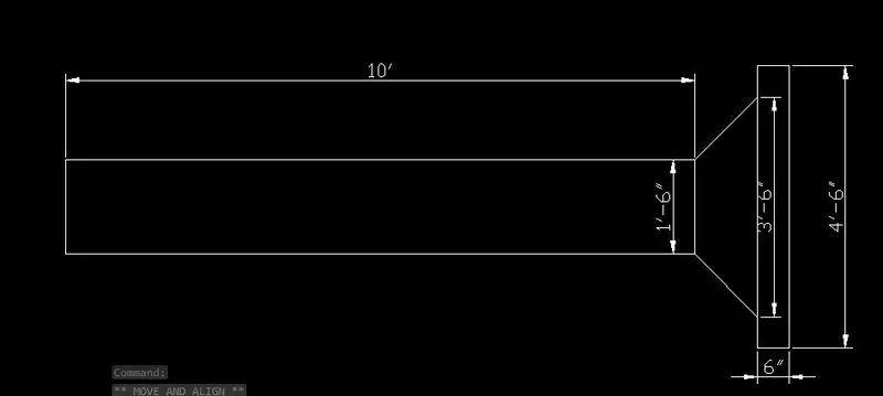
draw rectangle with dimension of 10'x 1'6".
xplode the rectangle.
take line command draw the 1' line with refrence of this line draw the vetical line at distance of 1'9" up and 1'9" down .
and extend the line 6" with width of 6" make it in to rectangle.
joing the endpoint of 1'6" line and 3"6" line.
dimension are provided.
second model
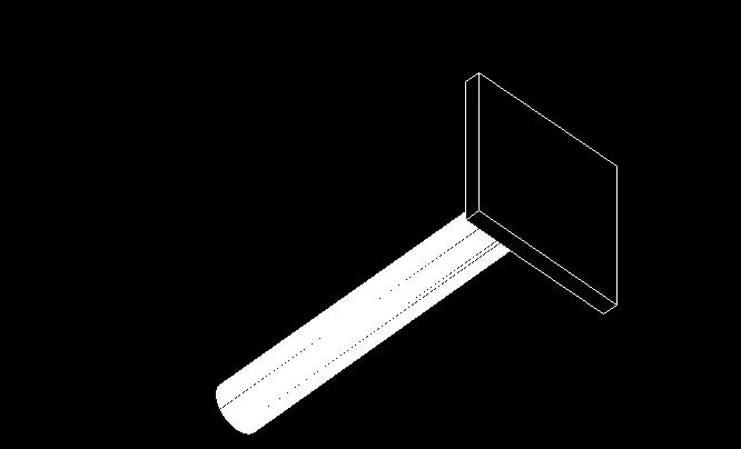
draw circle with diameter of 1'6"
copy it placed at height 0f 10'.
take surf tab value as 1000.
take ruled surface select the two circle the 1000 line are joined to make surface.
same procedure is repeated to the 1'6"circle and 3'6" line and take box with dimension 4'6"x4'6"x6".
take hide command to hide unseen lines which are back of the box.
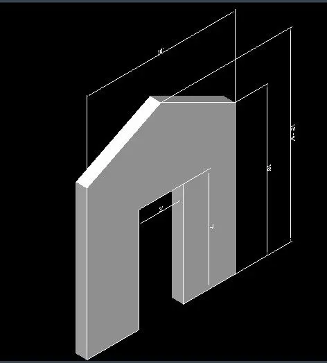
Aim: To Create the 3d model of a wall .
Tools i used
line
trim
rectangle
extrude
dimension
procedure :
put the visual style in the 2d wire fame
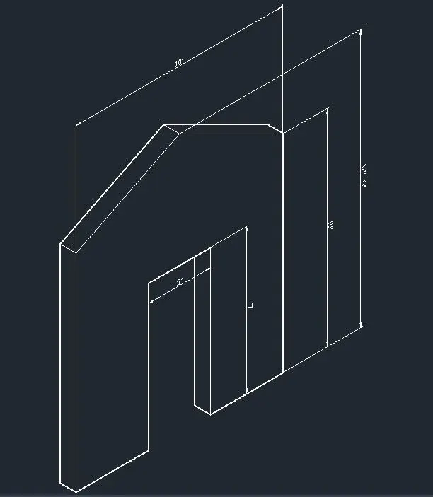
draw rectangle 10'x12'6".
explode it
take the bootom length line as reference draw the 1'6" line left and 1'6" right.
make them join and end point take as refrence draw the vertical line 7' at the both sides.
join the two vetical lines.
take offset command 2'6" offset line from top .
take trim command remove bottom 3' line.
join the endpoint of the offset line endpoint to the midpoint of the top line .
remove side line.
switch 3d view.
rotate the model in x -axis with 90 degree.
make the geometry in to region and extrude 9" towards y-direction.
dimensions are provided to it.
Result: I have Created a 3D Furniture element .
I have Create the 3d Model of an Isolated footing.
I have Created the 3D view of the AASTHO Type Girder.
I have Created a 3d Model of a drop column with panel .
I have Create the 3d model of a wall .