Creating various 3D Models like Furniture, Footing, Girder, Column drop with panel and Gable Wall in AutoCad
AIM :-Creating various 3D Models like Furniture, Footing, Girder, Column drop with panel and Gable Wall in AutoCad
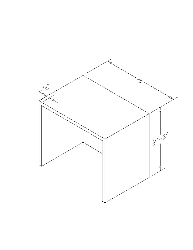
1. Create a 3D Furniture element as shown in the Figure. Assume dimensions which are missing.
procedure :
steps :-
- Open AutoCAD application
- open new drawing sheet
- set the unit Inches
- change the workspace as 3D basics
- change it into SE isometric
- take the line command
- draw the outline of the table 2'6'' x 3'
- offset the line at 2'' inside
- draw the rec as 2'4''x 2'8'' and move it in the position
- take EXT command
- select the object
- press ENTER
- give the height as 2'6
- simillarly extrude inner box

- go to visual syle
- select the visual style as any one that u want
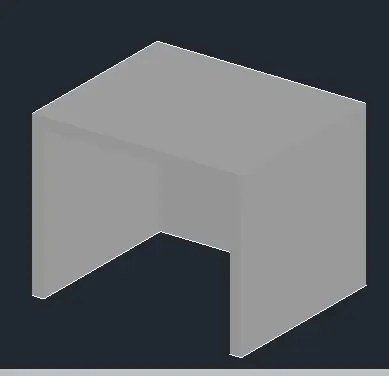
RESULT:-
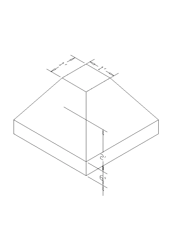
2. Create the 3d Model of an Isolated footing as shown in Figure.
PROCEDURE:
STEPS:-
- Open AutoCAD application
- open new drawing sheet
- set the unit Inches
- change the workspace as 3D basics
- change it into SE isometric.
- Take the rec command of size 4'x4'
- and draw another rec for column in center of size 1'x1'
- take M command select the inner column box
- select the base point as center
- give the dispacement distance as 2'
- press enter
- take EXT command
- select the object as 4'x4' rec
- press ENTER
- give the height as 6''
- take the line command
- draw the line that u want to complete the figure by Orbiting the object to better view
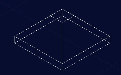
- give the visual style as hidden
RESULT:-
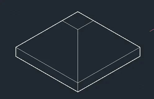
3. Create the 3D view of the AASTHO Type Girder.
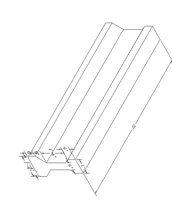
PROCEDURE:
STEPS:-
- Open AutoCAD application
- open new drawing sheet
- set the unit Inches
- change the workspace as 3D basics
- change it into SE isometric.
- take the LINE command
- draw the outline as given

- take EXTRUDE command
- select the object
- press enter
- give the height as 10'
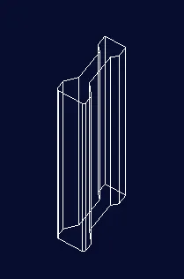
- give the visual style that u want
RESULT:-
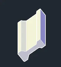
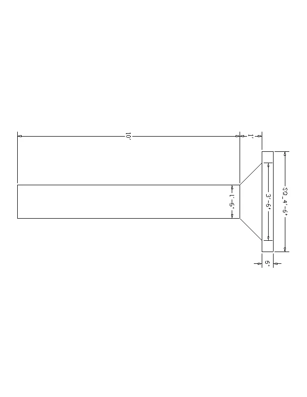
4. Create a 3d Model of a drop column with panel as shown in section and isometric view.
PROCEDURE:
STEPS:-
- Open AutoCAD application
- open new drawing sheet
- set the unit Inches
- change the workspace as 3D basics
- change it into SE isometric.
- take the REC command
- give the size as 4'x4'
- again take rec command of size 3'6''x3'6'' and 1'6''x 1'6''
- place it in appropriate position
- take M command
- select the box of 1'6''x1'6'' size
- select the base point as center
- give the displacement at 1'6''
- again take move command - select the object as 3'6'' box
- select the base point as centre
- give the displacement at 6''
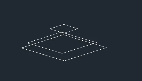
- take the EXT command
- select the bottommost box
- press enter
- give the height as 6''
- enter
- take EXT command
- select the object as column box
- press enter
- give the height as 10'
- take the line tool
- draw the lines that make the object is complete by orbiting the figure
- give the visual style
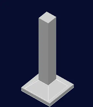
RESULE:-
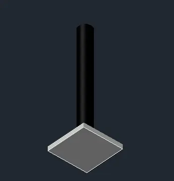
PROCEDURE:
STEPS:-
- Open AutoCAD application
- open new drawing sheet
- set the unit Inches
- change the workspace as 3D basics
- change it into SE isometric.
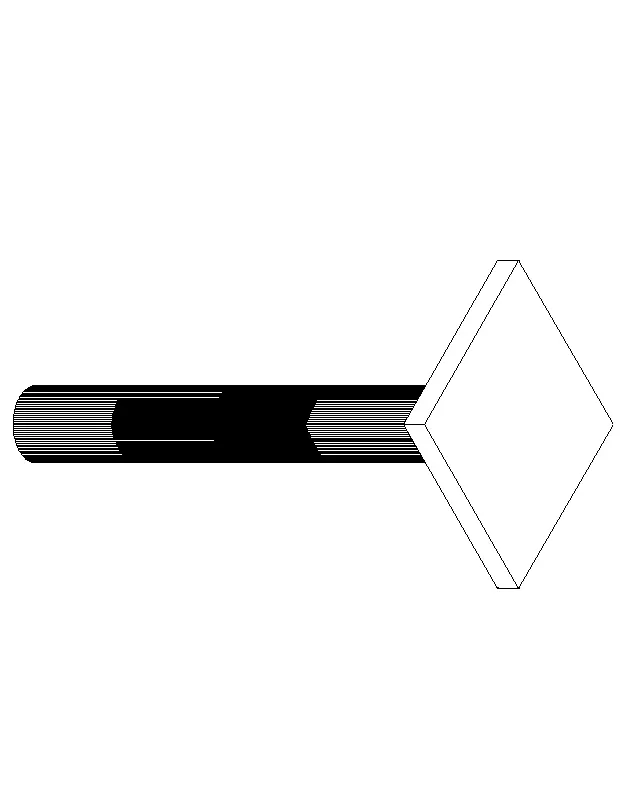
- preocedure is same as that of 4 object excepting the column
- take the visual style as 2D wireframe
- delete the column
- take the circle command
- select the center point
- specify the diameter as 1'6''
- press enter
- take edgesurf command
- select the object as circle
- select the path as bottom box that just beleo the circle
- take EXT command
- select the circle
- press enter
- give the height as 10' assumed
- now the object is ready
- give the visual style .
- Give the color to column as shown by selecting the column and go to the propertiees as colour.
RESULT:-
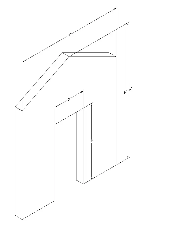
5. Create the 3d model of a wall as shown in Figure. Consider wall thickness as 9”.
PROCEDURE:
STEPS:-
- Open AutoCAD application
- open new drawing sheet
- set the unit Inches
- change the workspace as 3D basics
- change it into SE isometric.
- take the line command
- draw the outline as pre the given dimensions
- take EXT command at distance of 9''
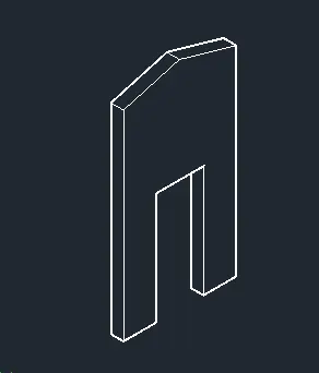
- give the visual style as u want
RESULT:-