Creating a Floor plan, Footing detail and Isometric view using AutoCad
Challenge NO.2
Ans-1. Aim: To draw the Foundation of L.B.S showing plinth height, steps, wall
Procedure to draw:
Line command-Enter-specify first point: Click anywhere on the autocad drawing sheet where u want to start;
Specify next point : @0.90<0
Specify next point : @0.25<90
Specify next point : @0.90<180
Specify next point :@0.25<270 or c for close or Enter or escape from the command;
XLINE command: vertical, take the cursor in the middle of the top of created rectangle and draw the line through that point;
Escape from the command by esc botton;
OFFSET command: select the object that are to be offset
Specify distance through : 0.25 and click right and left of the selected object;
Select object i.e middle vertical line and specify distance through: 0.20 and click right and left of the selected object;
Select object i.e middle vertical line and specify distance through: 0.15 and click right and left of the selected object;
Select the outer line of wall that are created previous in the right ,
Specify offset distance through: say 1.00 (assume) and click on the right;
Select the left outer line of wall, specify distance of offset: 0.15, click in the left;
Select the previous line created, specify distance of offset: 0.15, click in the left ;
Select the previous line , specify distance of offset: 0.15, click in the left ;
Select the previous line created, specify distance of offset: 0.15, click in the left;
Select the previous line, specify distance of offset: 0.15, click in the left ;
Escape form the command : esc or c or enter;
OFFSET command: select the object (topmost line of rectangle that created earlier);
Specify distance through: 0.250, click on the top of selected object;
Specify distance through : 0.40, click on the top of previous object created;
Specify distance through : 0.250, click on the top of previous object created;
Specify distance through : 0.150, click on the top of previous object created;
Specify distance through : 0.150, click on the top of previous object created;
Specify distance through : 0.150, click on the top of previous object created;
Specify distance through : 0.150, click on the top of previous object created;
Specify distance through : 0.150, click on the top of previous object created;
Specify distance through : 0.05, click on the top of previous object created;
Specify distance through : 1.00, click on the top of previous object created;
Escape from the command,
TRIM command: enter- select the object (line) that are to be trim-enter;
[from above command all the lines that are unwanted to be used are trim ]
Escape from command,
Dimension command: give the dimension of the particular by selecting the object/line

Ans-2. Aim : to draw the cross section of Isolated Footing in autoCAD.
Procedure to draw:
LINE command:- enter
Specify first point: click anywhere where u want to start line;
Specify next point : @1.00<0
Escape from command,
XLINE command : vertical- click in the middle of the line that are created-enter;
OFFSET command: select the vertical central line - specify the distance through : 0.500, click on left and right of the selected object;
Select the object that are created previous in the left, specify distance through : 0.38, click on the right of selected object;
Select the object that are created previous in the Right, specify distance through : 0.38, click on the left of selected object;
OFFSET command: select the left column line , specify the distance through: 0.040, click on the left of selected line ;
select the right column line , specify the distance through: 0.040, click on the right of selected line ;
Escape from the command,
OFFSET command : select the bottom horizontal line, specify the distance through: 0.040, click on the top of selected object/line;
Select previous line, specify distance through: 0.15, click on the top of selected line;
Select previous line, specify the distance through : 0.25, click on the top of the selected object/line;
Select previous line, specify the distance through : 1.60, click on the top of the selected object/line;
Escape from the command,
LINE command: join the slope by creating the line by clicking the endpoints in both sides;
Escape from command,
TRIM command: trim the lines that are not useful by the selecting those lines/objects
OFFSET command: select the topmost horizontal line, specify the distance through: 0.20, click on the down of the selected object/lines,
Create the 9 no.of offsets by doing same;
Escape from the command,
TRIM command: trim unwanted lines by selecting them and enter;
Click on the reinforcement line, click right and go to lengthen command , specify distance as 0.04 , click on the side where want to desrease the line (click inside);
Do the same process for other end of the line ;
LINE command: click on the right side end point of the right reinforcement line ;
Specify next point: @0.075<90 ……(Assumed distance 0.075);
Escape from the command,
COPY command : select the line (reinforcement ) in the right side;
Select the corner of the line as base point ;
Click on the lift side where you want to create the copy of the selected object.

Ans-3 Aim: To draw the Diagram of a Two Bedroom Building in autoCAD.
Procedure to draw:
LINE command: specify the first point – click anywhere on the screen where you want to start ;
Specify next point: @0.90<180
Specify next point: @1.00<270
Specify next point : @0.90<0
Specify next point : @4.20<270
Specify next point : @3.60<0
Specify next point : @4.20<90
Specify next point : @0.90<0
Specify next point : @1.00<90
Specify next point : @0.90<180
Specify next point : @3.60<90
Specify next point : @3.60<180
Specify next point : @3.60<270 or c for close
OFFSET command: Select the left outermost line, specify distance through: 0.30, click on the right of selected object/line;
Select the offseted line, specify distance through: 0.30, click on the right of selected object/line;
Select the Right outermost line, specify distance through: 0.30, click on the left of selected object/line;
Select the offseted line, specify distance through: 0.30, click on the left of selected object/line;
To create opening of door:
Select the right outer line of the bedroom , specify the distance through: 1.80, click on the left of selected line;
Select the left outer line of the bedroom , specify the distance through: 0.90, click on the Right of selected line;
Enter,
TRIM command: trim all the lines that are unusefull.

Ans-4 AIM: To draw the Cross section of the Load Bearing Wall showing foundation details
Procedure to draw:
Line command-Enter-specify first point: Click anywhere on the autocad drawing sheet where u want to start;
Specify next point : @0.90<0
Specify next point : @0.45<90
Specify next point : @0.90<180
Specify next point :@0.45<270 or c for close or Enter or escape from the command;
XLINE command: vertical, take the cursor in the middle of the top of created rectangle and draw the line through that point;
Enter,
OFFSET command : select the middle vertical line, specify distance through: 0.30, click on the left and right of selected line;
select the middle vertical line, specify distance through: 0.250, click on the left and right of selected line;
select the middle vertical line, specify distance through: 0.20, click on the left and right of selected line;
select the middle vertical line, specify distance through: 0.150, click on the left and right of selected line;
enter,
offset command: select the topmost line of rectangle ,specify distance through: 0.40, click on top of selected line;
select previous created line, specify distance through: 0.30, click on the top of selected line;
select previous created line, specify distance through: 0.60, click on the top of selected line;
select previous created line, specify distance through: 1.00, click on the top of selected line;
enter,
TRIM command: select the lines that are not in use, enter;
Enter.

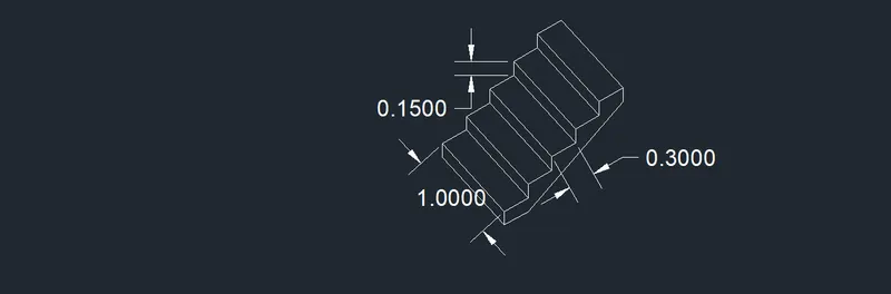
Ans-5. AIM: To draw the ISOMETRIC VIEW OF STEPS
Procedure to draw: DS command : select isometric snap;
Line command-Enter-specify first point: Click anywhere on the autocad drawing sheet where u want to start;
Specify next point : @0.30<180
Specify next point : @0.15<90
Specify next point : @0.30<30
Specify next point : @0.15<90
Specify next point : @0.30<30
Specify next point : @0.15<90
Specify next point : @0.30<30
Specify next point : @0.15<90
Specify next point : @0.30<30
Specify next point : @0.15<90
Specify next point : @0.30<30
Specify next point : @0.15<270
Enter or c for close;
Copy command: select the steps, select bottommost corner point as base point, specify the distance through: 1.00. and click on the top;
Enter,
LINE command: Draw the line by clicking the endpoints of the corners, like viz create all the lines that are use to finish the steps drawing;
Enter.
Ans-6. AIM: To draw the ISOMETRIC VIEW OF GABLE WALL
Procedure to draw:
DS command: select the isometric snap;
LINE command: click anywhere on screen as first point;
Specify next point: @0.30<150
Specify next point:@3.00<270
Specify next point:@0.30<330
Specify next point:@1.00<30
Specify next point: @2.42<90
Specify next point:@1.00<30
Specify next point:@2.42<270
Specify next point:@1.00<30
Specify next point:@3.00<90
Specify next point:@1.52<170.54
Specify next point: @350.54 or c for close
LINE command: click first point right top corner of the wall
Specify next point:@0.30<150
Enter,
Line command: specify first point on the right bottom corner of the door;
Specify next point:@0.30<150;
Then join the vertical line by click exact vertical point (ortho on);
Enter,
COPY command: select the both lines of roof, specify base point in the corner of wall, specify the distance: 0.30, enter;
JOIN command : select the boundary line up to line join, select the line that as to join to boundary, enter