Creating various 3D Models like Furniture, Footing, Girder, Column drop with panel and Gable Wall in AutoCad
ANSWERS :
AIM : To Create various 3D Models like Furniture, Footing, Girder, Column drop with panel and Gable Wall in AutoCad
INTRODUCTION : 3D Modelling of the Given objects are Drawn by AutoCad from three dimensionsal aspect by showing size, area, Height, surface adn Texture from various tools such as Line, Rectangle, Loft, Extrude, subtract, union, UCS, Region, Boundary and other tools
To Cancel Selected Command Press “ESC”
To Invoke Previously Selected Command Press “ENTER”4
PROCEDURE :
Go to START MENU, select AutoCAD 2022.
In the Command line type in: STARTUP [ENTER]
Enter new value of startup: 1
Go to Application Menu and select New
In the 'Create New Drawing' dialog box, we do the Advanced Setup and select the 'Engineering' unit of measurement and select precision as 0'-0.0"
Enter 'UNITS' command in the command tab.
In the Drawing Units dialog box, select 'Engineering' in Type; 0'-0" in Precision; and 'Inches' in Insertion scale.
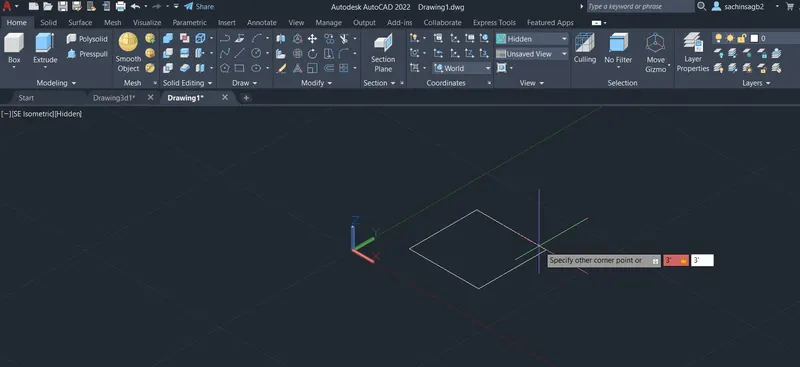
RECTANGLE : Specify the first point of the Rectangle and Specify the other as 3',3'
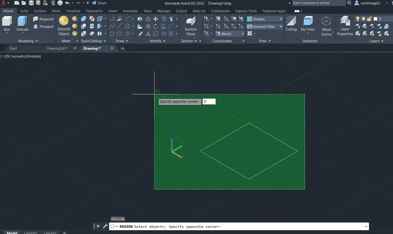
REGION : select the object and press enter a reagion will be created
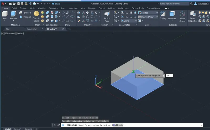
PRESSPULL :Select the object and Specifyt thr extrusion Height as 2'6"
Now the Solid is Created
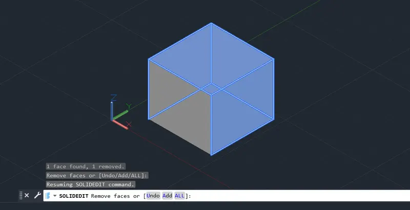
SOLIDEDIT : Remove the unwanted faces where shell has to be created
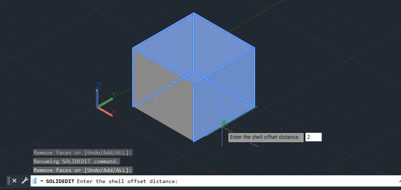
Specify the shell distance as 2"
Now shell ids created
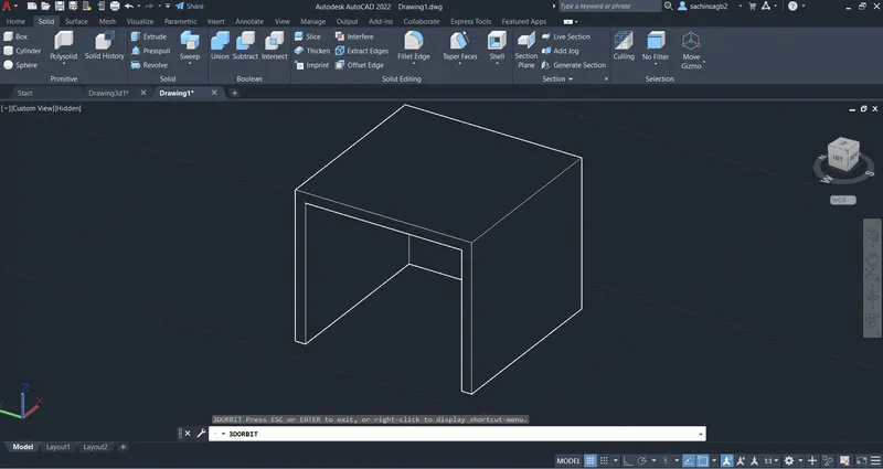
ANNOTATION : go to tools ribbon select annotation and pick Dimension option
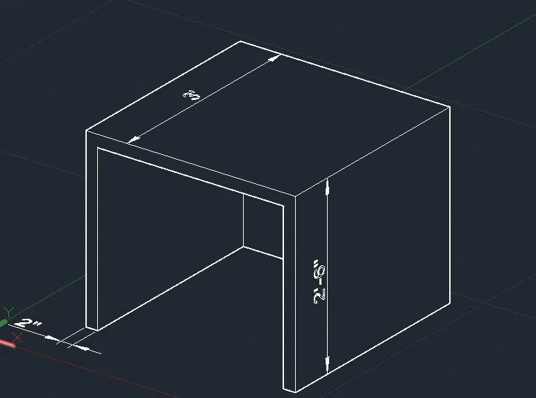
create the desired dimension lines on required surfaces
RESULT :
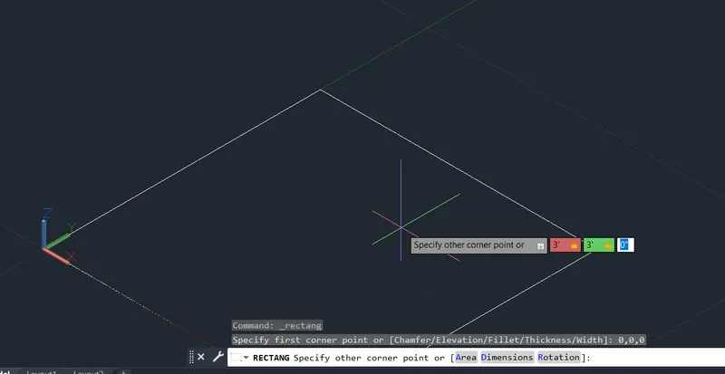
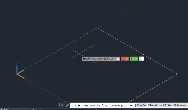
RECTANGLE: Specify the first point as 1,1,2 and next point as 1',1',2'
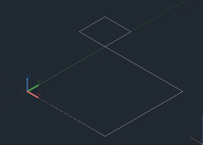
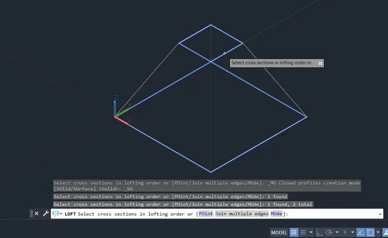
LOFT : select the loft option select the Rectangle cross section in lofting order to create the Loft
PRESSPULL : select the recently created region and Specify the extrusion as -6" and click to create
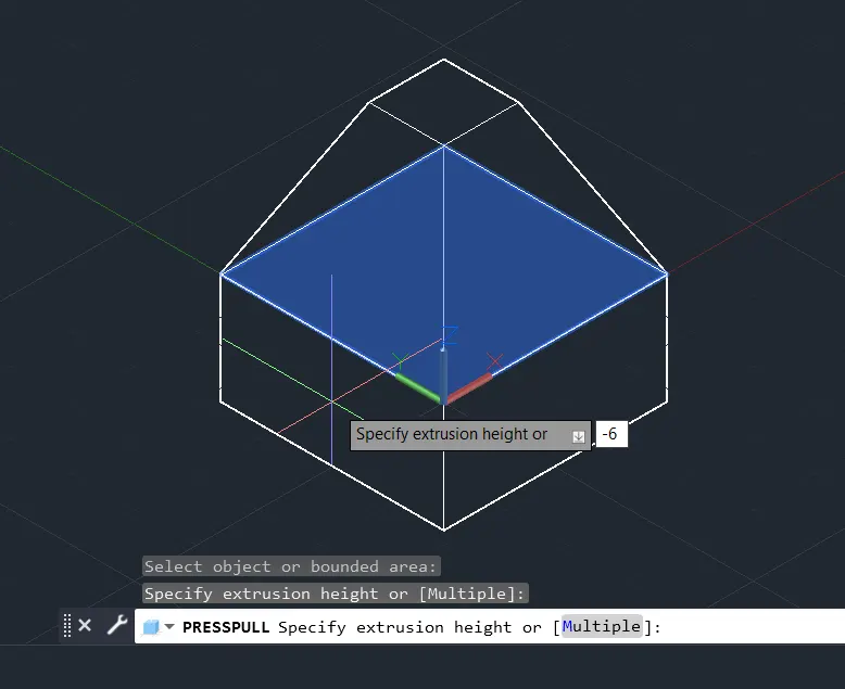
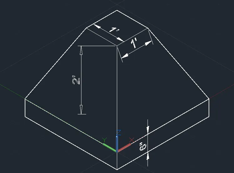
ANNOTATION : go to tools ribbon select annotation and pick Dimension option
create the desired dimension lines on required surfaces
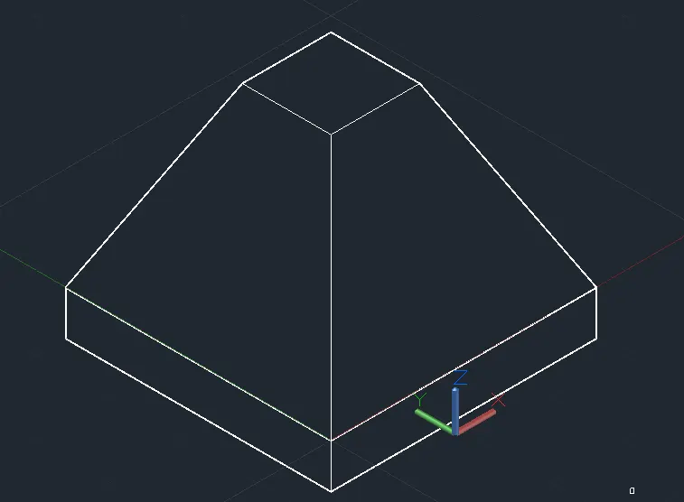
RESULT :
Line select the line tool and specify the first point and Next point as 6,0,0
Next point as 6,6,0
Next point as 1'6" ,0 ,0
Next point as 6,-6, 0
Next point as 6,0,0
Next point as 0,1"6, 0
Next point as -6,0,0
Next point as -6, 6, 0
Next point as -1'6" ,0 ,0
Next point as -6,6,0
Close the Line to complete the Geometry

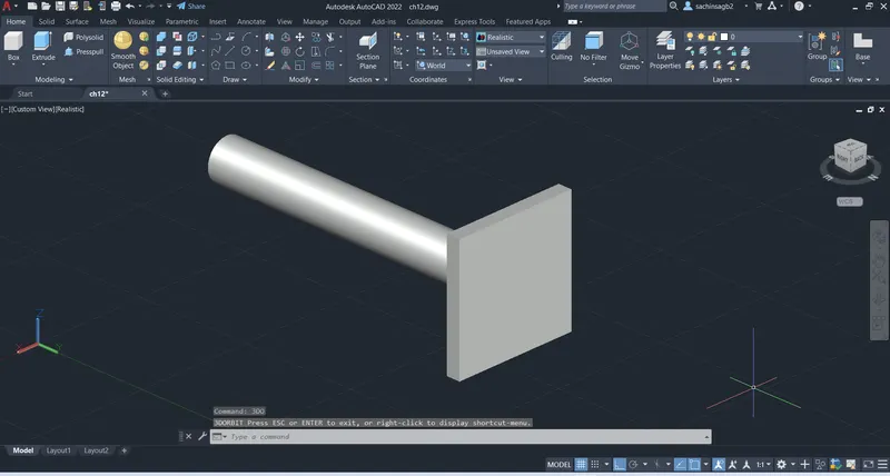
Now the object is created use 3DORBIT to view the object in desired view/ angle
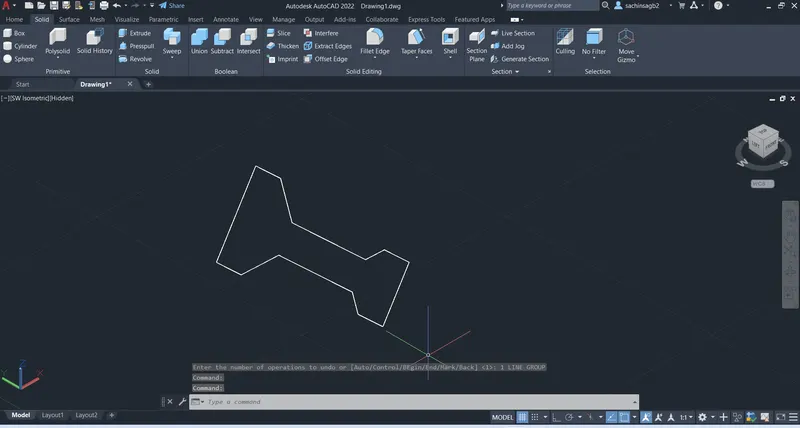
LINE: Create the Line and of length in 10'
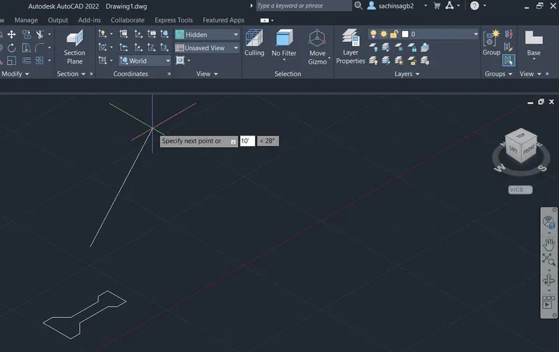
REGION : Select the Geometry and Create the Geometry
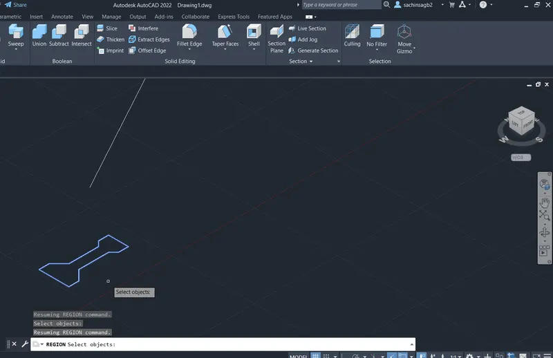
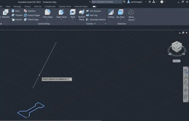
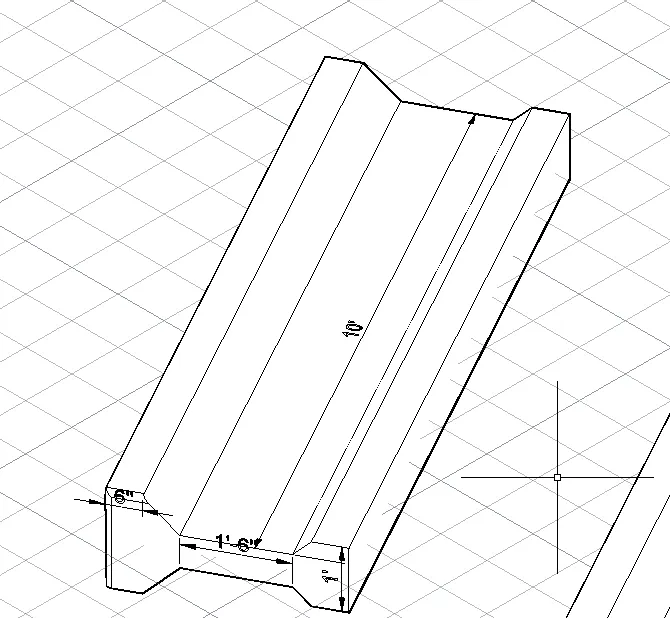
SWEEP: Select the Sweep option and Select sweep object as Geometry and Sweep path as Line
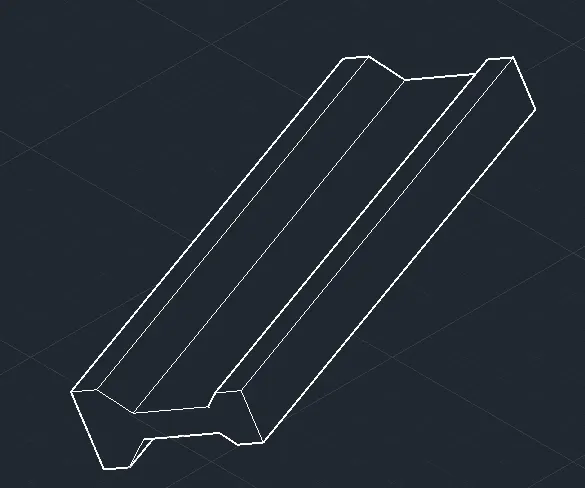
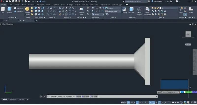
Desired 3D object is Created use 3DORBIT to view the object in different angle and View
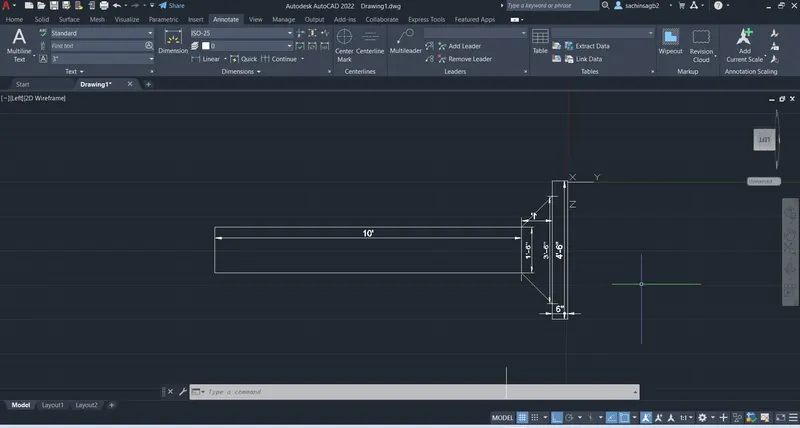
ANNOTATION : go to tools ribbon select annotation and pick Dimension option
create the desired dimension lines on required surfaces
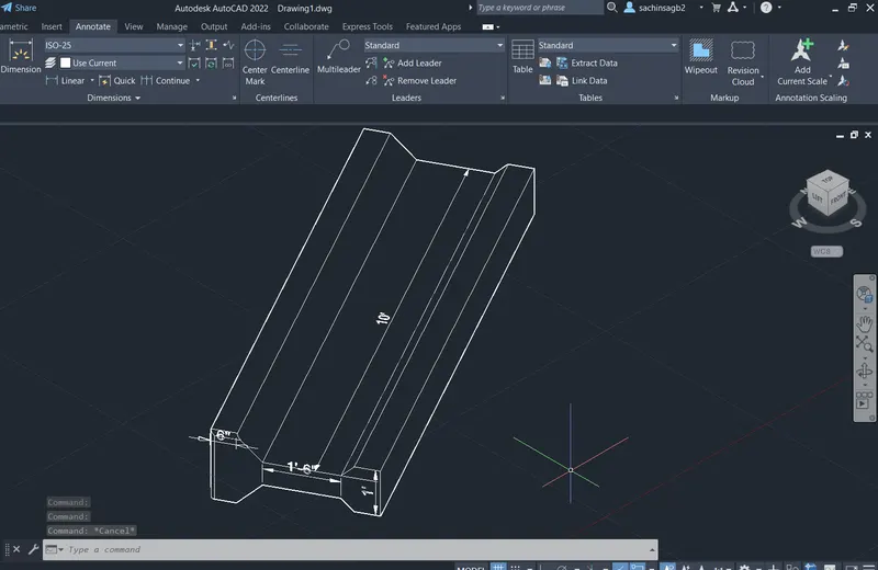
RESULT:
BOX : Specify the First point as 0,0,0 and Other end as 4'6,4'6,0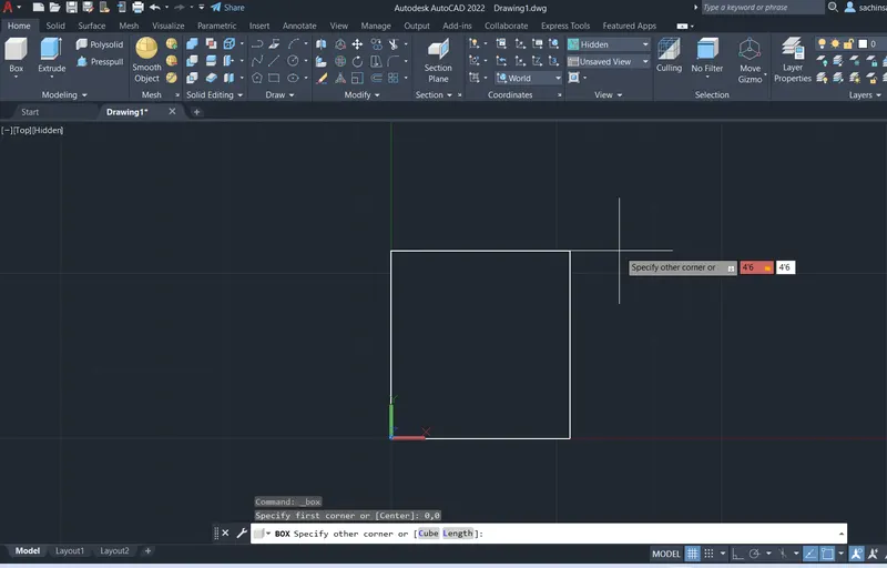
Specify the Height of Box as 6"
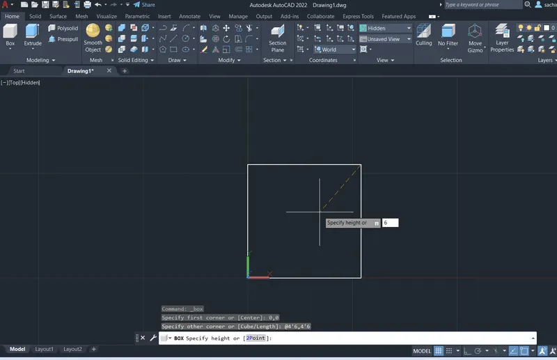
Now the Solid rectangle is created
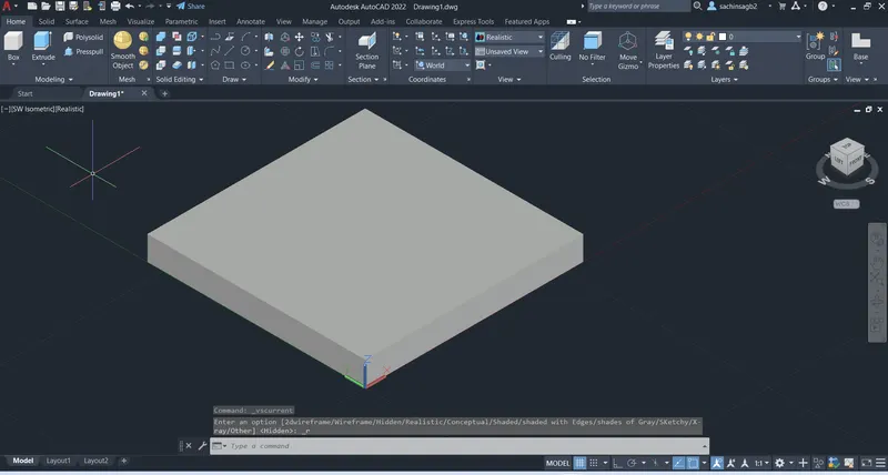
RECTANGLE : Specify the first point as 6",6",6" and other corner as 3'6", 3'6", 6"
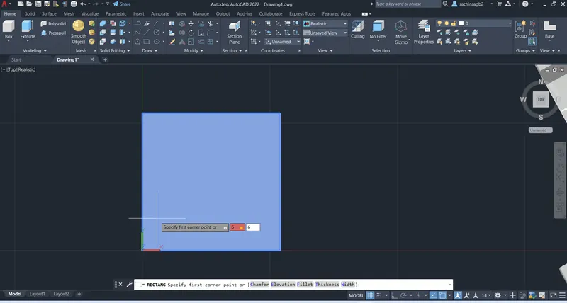
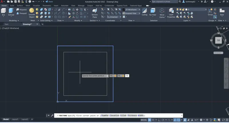
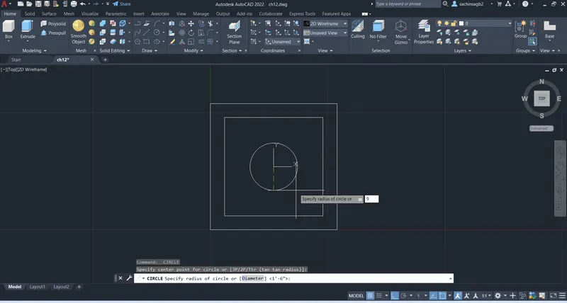
CIRCLE : Specify the Centre point of the Circle as 2'3",2'3" ,1'6"
and Radius of the Circle as 9"

LOFT : select the loft option select the Rectangle cross section in lofting order to create the Loft
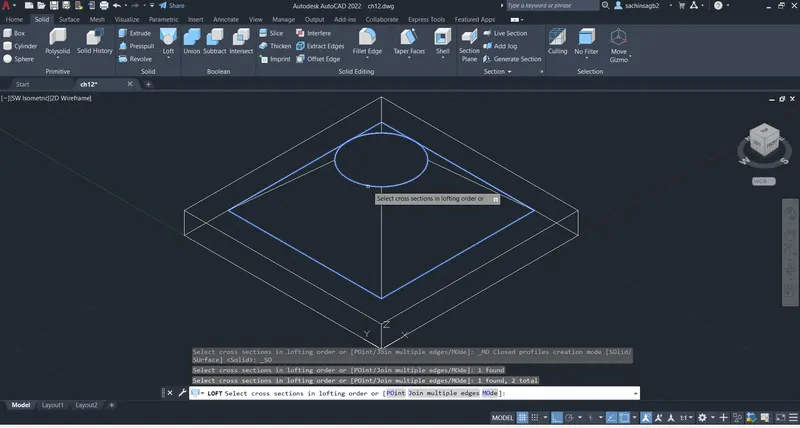
REGION: Create the Region on the top of the Circle
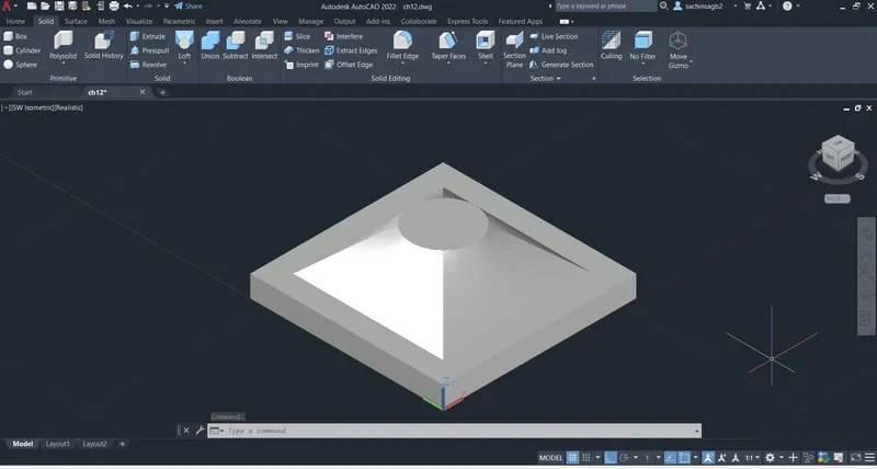
EXTRUDE : Select the Circle region and Specify the Extrusion length as 10'
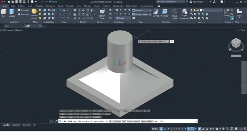
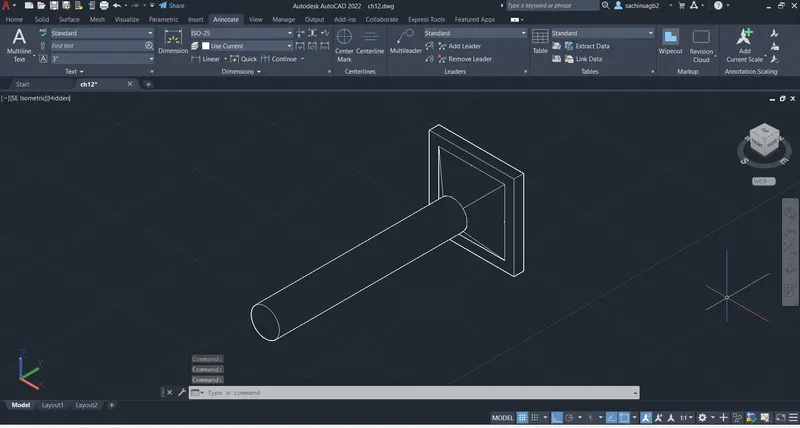
Desired 3D object is Created use 3DORBIT to view the object in different angle and View
ANNOTATION : go to tools ribbon select annotation and pick Dimension option
create the desired dimension lines on required surfaces
RESULT:
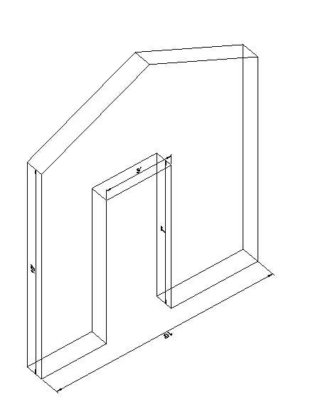
GABLE WALL:
LINE : Select the Line and specify the first pint and next point as 3',0,0
Specify the Next Point as 0,7',0
Specify the Next Point as 3',0,0
Specify the Next Point as 0,-7,0
Specify the Next Point as 3',0,0
Specify the Next Point as 10',0,0
Specify the Next Point as -5',2'6,0
Specify the Next Point as -5',-2'6,0
Specify the Next Point as -10',0,0
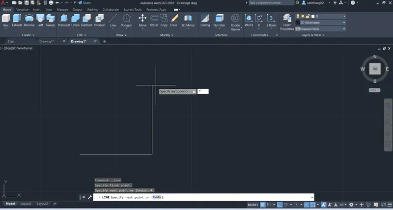
Now the Geometry is Created
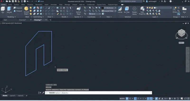
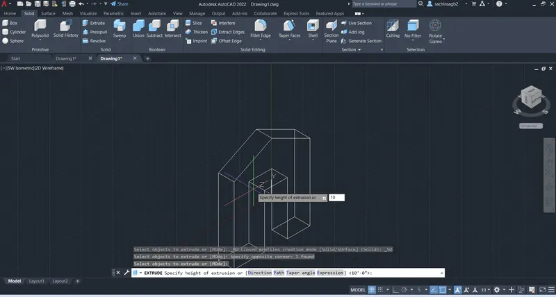
EXTRUDE : select the extrude option and select the Geometry , Height of extrusion as 10"
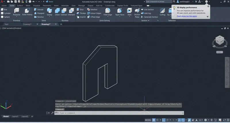
RESULT :