Creating various 3D Models like Furniture, Footing, Girder, Column drop with panel and Gable Wall in AutoCad
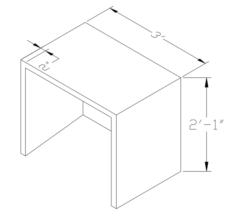
Aim: - To Create a 3D Furniture element as shown in the Figure using AutoCAD 3D.
Introduction: - The furniture element is drawn using proper 3D tools, primarily using the Line tool and after sketching, the dimensions and text are provided. The procedure of drawing is explained in detail with diagrams of each step and the final result is given.
All dimensions are taken in inches.
PROCEDURE: -
Before we start the drawings we need to set up the drawing as Metric and the units into Decimal Units.
Following are the steps in order to set up the drawing as Imperial Template and the units into Engineering Units.
- Go to Application Menu or click CTRL + N (New)
- Click on New from the Application Menu
- A popup menu appears, click on the first tab known as Start from Scratch > Select imperial
- Now click on the third tab known as Use a Wizard > Go to Advance setup > A Dialog box appears > Select the unit of measurement as Decimal > Press Next > select Angle as Decimal Degrees > Press Next > Select Angle Measure > Press Next > Select Angle Direction > Press Next > Select Area > Click Finish
- Set the page limit by entering Limits in the command tab. The lower left corner is specified as 0,0 and the upper right corner is specified as 100', 100'.
- In the Drawing Units dialog box, select 'Engineering' in Type; ' 0 ' in Precision; and 'Inches' in Insertion scale.
- Click OK
Now,
- Click on the Workspace Switching Tab
- Change the workspace from 2D drafting and annotation to 3D Modelling.
- Now we are all set to go.
Now,
- Draw a 2'6" line in z direction.
- Draw a 3' line in y direction.
- Draw again a 2'6" line in z direction downward.
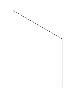
- Draw the 2" widht of the above drawn lines.
- Take table width = 2'
- Again draw the 2'6" in +z direction.
- Draw 3' in +y direction.
- Again draw 2'6" in -z direction
- Trim the extra lines.
- So we have the following drawing.
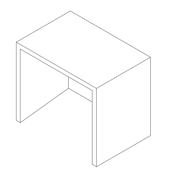
Now, its time for dimension
- Type DST or dimensionstyle
- A dialogue box appears.
- Go to Modify
- Then go to Text
- Set the text height as 2.5".
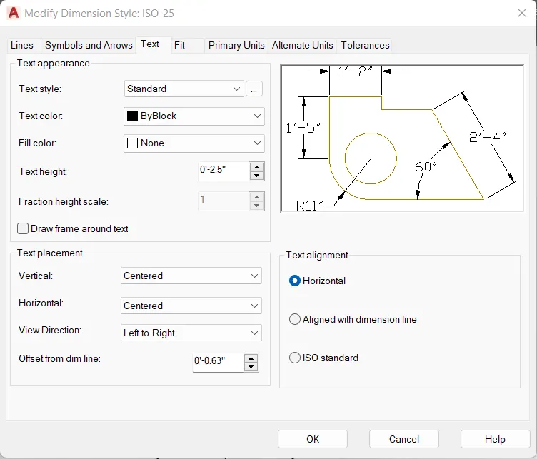
- Similarly go to Arrow
- Set the arrow size as 2.5".
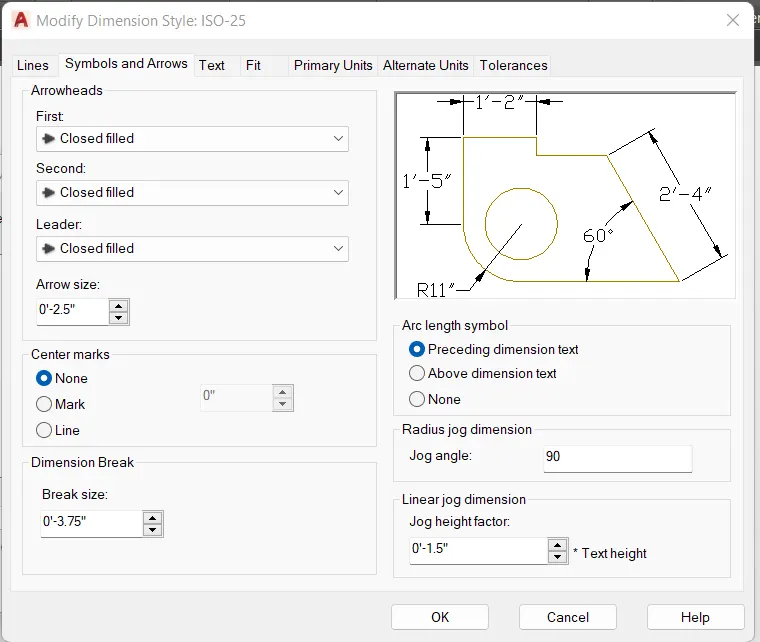
Now,
- Go ribbon tab
- CLick on Visualize
- Different tabs will open.
- Go to UCS.
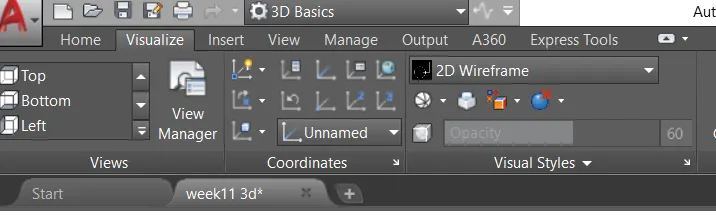
- Click on the object UCS.
- And bring the UCS where u need to provide the dimension.
- So we have the following drawing after the dimensions.
Result: -
-------------------------------------------------------------------X---------------------------------------------------------------------------------------
Aim: - To Create the 3d Model of an Isolated footing as shown in Figure, using AutoCAD 3D.
Introduction: - The Isolated footing is drawn using proper 3D tools, primarily using the Line tool and after sketching, the dimensions and text are provided. The procedure of drawing is explained in detail with diagrams of each step and the final result is given.
All dimensions are taken in inches.
PROCEDURE: -
Before we start the drawings we need to set up the drawing as Metric and the units into Decimal Units.
Following are the steps in order to set up the drawing as Imperial Template and the units into Engineering Units.
- Go to Application Menu or click CTRL + N (New)
- Click on New from the Application Menu
- A popup menu appears, click on the first tab known as Start from Scratch > Select imperial
- Now click on the third tab known as Use a Wizard > Go to Advance setup > A Dialog box appears > Select the unit of measurement as Decimal > Press Next > select Angle as Decimal Degrees > Press Next > Select Angle Measure > Press Next > Select Angle Direction > Press Next > Select Area > Click Finish
- Set the page limit by entering Limits in the command tab. The lower left corner is specified as 0,0 and the upper right corner is specified as 100', 100'.
- In the Drawing Units dialog box, select 'Engineering' in Type; ' 0 ' in Precision; and 'Inches' in Insertion scale.
- Click OK
Now,
- Click on the Workspace Switching Tab
- Change the workspace from 2D drafting and annotation to 3D Modelling.
- Now we are all set to go.
Now,
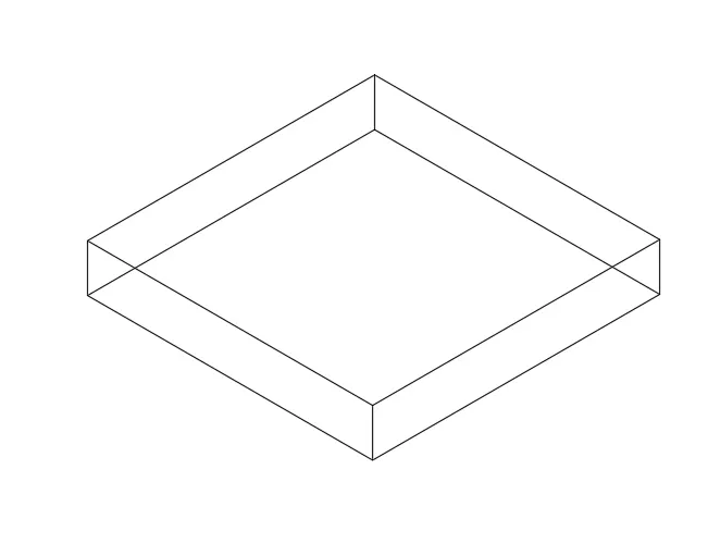
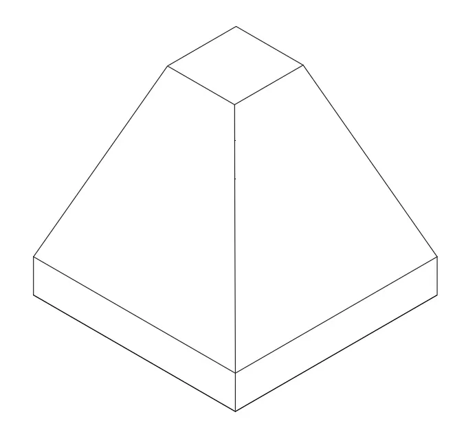
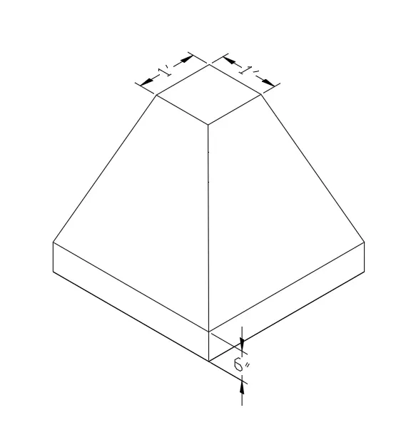
- Draw a 3' X 3' rectangle.
- Make it a region by
- Clicking on boundary > region.
- Then Extrude it to 6".
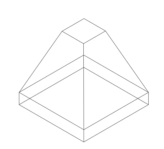
- Now draw another rectangle of 1' X 1'.
- And move it to a heigth of 2'6".
- Connect the corner points.
Now,
- In order to hide the extra lines of the footing.
- Type 3D face and select the faces to hide.
- Again draw the 2'6" in +z direction.
- Draw 3' in +y direction.
- Again draw 2'6" in -z direction
- Trim the extra lines.
- So we have the following drawing.
Now, its time for dimension
- Type DST or dimensionstyle
- A dialogue box appears.
- Go to Modify
- Then go to Text
- Set the text height as 2.5".
- Similarly go to Arrow
- Set the arrow size as 2.5".
Now, its time for dimension
- Go ribbon tab
- CLick on Visualize
- Different tabs will open.
- Go to UCS.
- Click on the object UCS.
- And bring the UCS where u need to provide the dimension.
- So we have the following drawing after the dimensions.
Result: -
-------------------------------------------------------------------X---------------------------------------------------------------------------------------
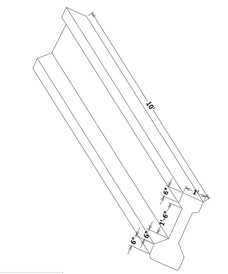
Aim: - To Create the 3D view of the AASTHO Type Girder as shown in Figure, using AutoCAD 3D.
Introduction: - The AASTHO Type Girder is drawn using proper 3D tools, primarily using the Line tool and after sketching, the dimensions and text are provided. The procedure of drawing is explained in detail with diagrams of each step and the final result is given.
All dimensions are taken in inches.
PROCEDURE: -
Before we start the drawings we need to set up the drawing as Metric and the units into Decimal Units.
Following are the steps in order to set up the drawing as Imperial Template and the units into Engineering Units.
- Go to Application Menu or click CTRL + N (New)
- Click on New from the Application Menu
- A popup menu appears, click on the first tab known as Start from Scratch > Select imperial
- Now click on the third tab known as Use a Wizard > Go to Advance setup > A Dialog box appears > Select the unit of measurement as Decimal > Press Next > select Angle as Decimal Degrees > Press Next > Select Angle Measure > Press Next > Select Angle Direction > Press Next > Select Area > Click Finish
- Set the page limit by entering Limits in the command tab. The lower left corner is specified as 0,0 and the upper right corner is specified as 100', 100'.
- In the Drawing Units dialog box, select 'Engineering' in Type; ' 0 ' in Precision; and 'Inches' in Insertion scale.
- Click OK
Now,
- Click on the Workspace Switching Tab
- Change the workspace from 2D drafting and annotation to 3D Modelling.
- Now we are all set to go.
Now,
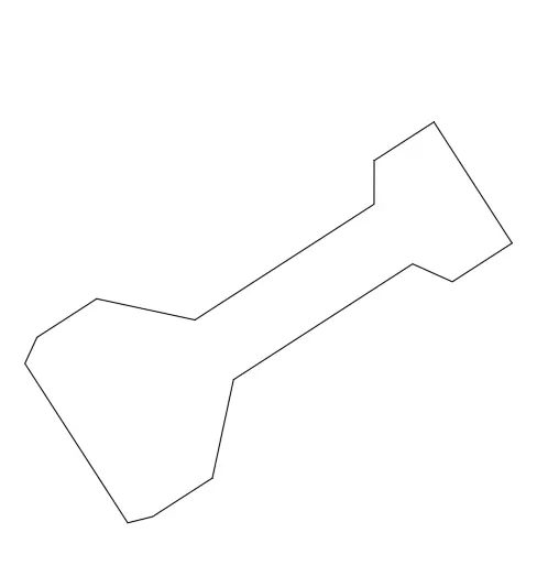
- Click on the top view
- Draw a 1'6" line.
- Draw a 1'4" line.
- Draw a 6" vertical line.
- Draw a chamfer of 6".
- Draw a vertical line of 1'6".
- Draw a chamfer.
- Again draw a vertical line 6".
- Draw a horizontal line of 1'.
- Now draw the length of the girder.
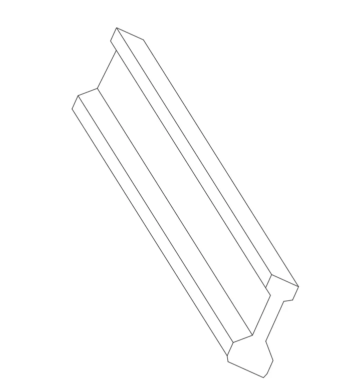
- Draw a length of 10'.
- Connect the corner points.
Now, its time for dimension
- Type DST or dimensionstyle
- A dialogue box appears.
- Go to Modify
- Then go to Text
- Set the text height as 2.5".
- Similarly go to Arrow
- Set the arrow size as 2.5".
Now, its time for dimension
- Go ribbon tab
- CLick on Visualize
- Different tabs will open.
- Go to UCS.
- Click on the object UCS.
- And bring the UCS where u need to provide the dimension.
- So we have the following drawing after the dimensions.
Result: -
-------------------------------------------------------------------X---------------------------------------------------------------------------------------
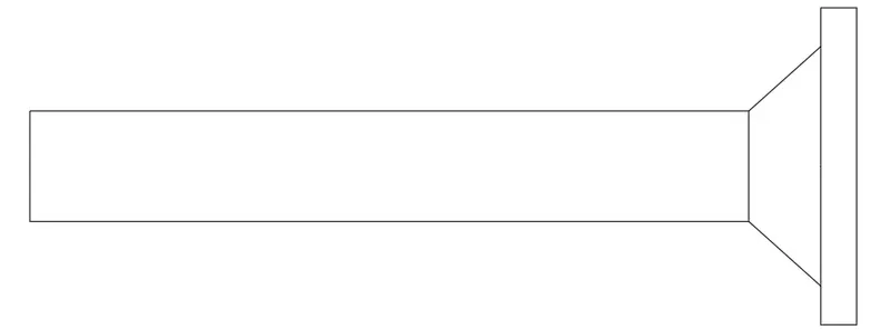
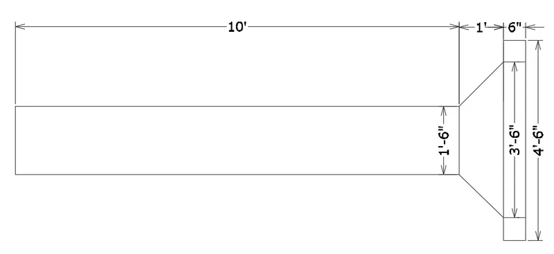
Aim: - To Create a 3d Model of a drop column with panel as shown in section and isometric view using AutoCAD 3D.
Introduction: - The drop column with panel is drawn using proper 3D tools, primarily using the Line tool and after sketching, the dimensions and text are provided. The procedure of drawing is explained in detail with diagrams of each step and the final result is given.
All dimensions are taken in inches.
PROCEDURE: -
Before we start the drawings we need to set up the drawing as Metric and the units into Decimal Units.
Following are the steps in order to set up the drawing as Imperial Template and the units into Engineering Units.
- Go to Application Menu or click CTRL + N (New)
- Click on New from the Application Menu
- A popup menu appears, click on the first tab known as Start from Scratch > Select imperial
- Now click on the third tab known as Use a Wizard > Go to Advance setup > A Dialog box appears > Select the unit of measurement as Decimal > Press Next > select Angle as Decimal Degrees > Press Next > Select Angle Measure > Press Next > Select Angle Direction > Press Next > Select Area > Click Finish
- Set the page limit by entering Limits in the command tab. The lower left corner is specified as 0,0 and the upper right corner is specified as 100', 100'.
- In the Drawing Units dialog box, select 'Engineering' in Type; ' 0 ' in Precision; and 'Inches' in Insertion scale.
- Click OK
Now,
- Click on the Workspace Switching Tab
- Change the workspace from 2D drafting and annotation to 3D Modelling.
- Now we are all set to go.
Now,
- Click on the top view
- Draw a 1'6" line.
- Draw a 10' line.
- Draw a 1'6" vertical line.
- Draw a chamfer of 10'.
- Draw a vertical line of 1'6".
- Draw a 3'6" vertical line.
- Again draw a offset line of 6".
Now, its time for dimension
- Type DST or dimensionstyle
- A dialogue box appears.
- Go to Modify
- Then go to Text
- Set the text height as 2.5".
- Similarly go to Arrow
- Set the arrow size as 2.5".
Now, its time for dimension
- Go ribbon tab
- CLick on Visualize
- Different tabs will open.
- Go to UCS.
- Click on the object UCS.
- And bring the UCS where u need to provide the dimension.
- So we have the following drawing after the dimensions.
Result: -
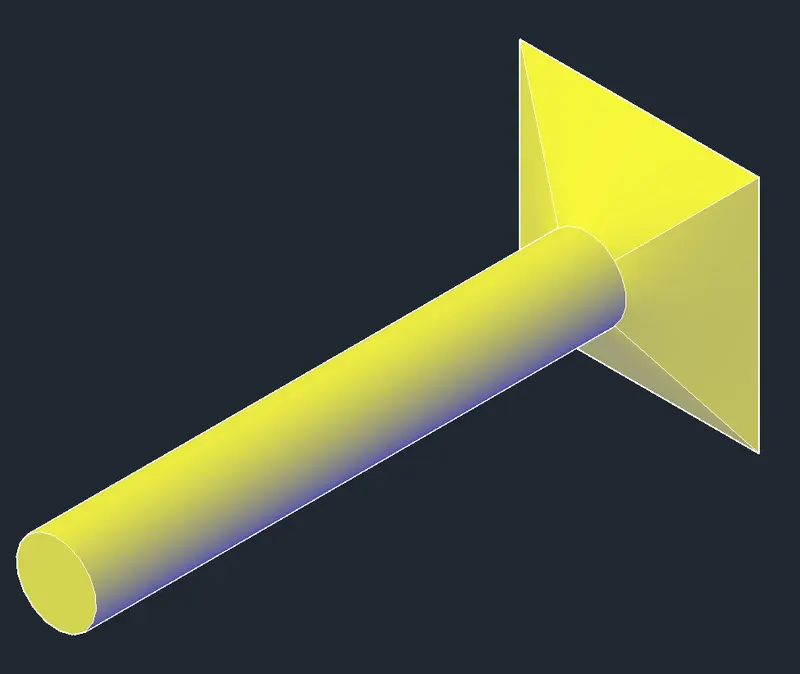
Now, let us draw the 3D model of the above drawing,
- Change the view to SW Isometric.
- Draw a circle of 1'6" dia
- Then draw a rectangle of 4'6" X 4'6".
- Now move the circle at the centre of the rectangle and place it as 1' above.
- Now type LOFT or select LOFT command from the modelling panel.
- Select the circle and the rectangle .
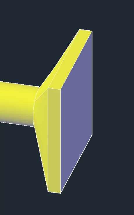
- Here's teh result

Now,
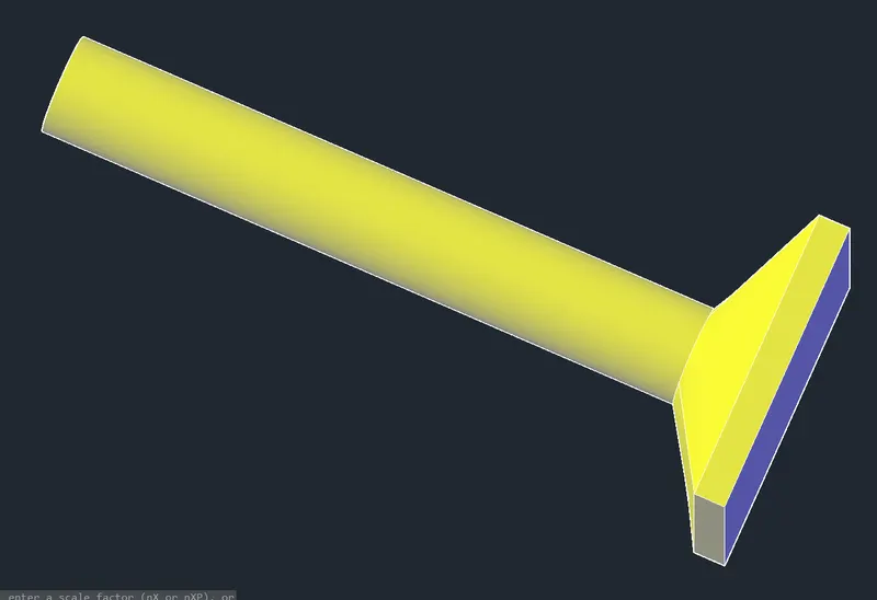
- Now type presspull or select presspul from the ribbon tab .
- Slect the circle and pull it to 10'.
Now,
- Presspull the rectangular footing.
- Pull it 6"
Result: -
-------------------------------------------------------------------X---------------------------------------------------------------------------------------
Aim: - To Create the 3d model of a wall as shown in Figure, using AutoCAD 3D.
Introduction: - The 3d model of a wall is drawn using proper 3D tools, primarily using the Line tool and after sketching, the dimensions and text are provided. The procedure of drawing is explained in detail with diagrams of each step and the final result is given.
All dimensions are taken in inches. Take wall thickness as 9”.
PROCEDURE: -
Before we start the drawings we need to set up the drawing as Metric and the units into Decimal Units.
Following are the steps in order to set up the drawing as Imperial Template and the units into Engineering Units.
- Go to Application Menu or click CTRL + N (New)
- Click on New from the Application Menu
- A popup menu appears, click on the first tab known as Start from Scratch > Select imperial
- Now click on the third tab known as Use a Wizard > Go to Advance setup > A Dialog box appears > Select the unit of measurement as Decimal > Press Next > select Angle as Decimal Degrees > Press Next > Select Angle Measure > Press Next > Select Angle Direction > Press Next > Select Area > Click Finish
- Set the page limit by entering Limits in the command tab. The lower left corner is specified as 0,0 and the upper right corner is specified as 100', 100'.
- In the Drawing Units dialog box, select 'Engineering' in Type; ' 0 ' in Precision; and 'Inches' in Insertion scale.
- Click OK
Now,
- Click on the Workspace Switching Tab
- Change the workspace from 2D drafting and annotation to 3D Modelling.
- Now we are all set to go.
Now,
- Set the view as SW Isometric.
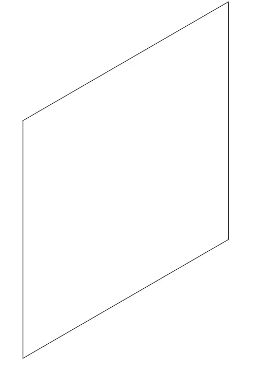
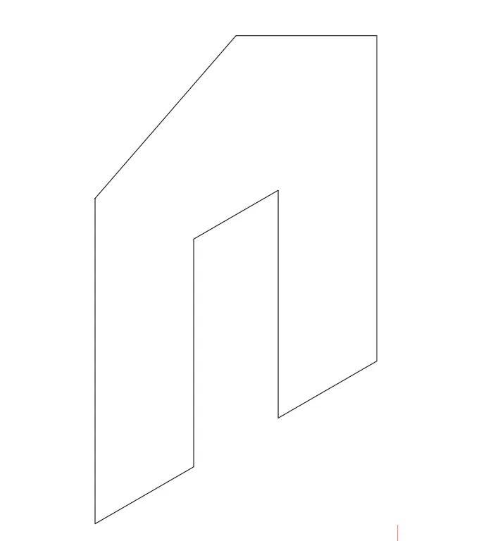
- Draw a 10' line.
- Draw a 10' vertical line.
- Draw a 10' horizontal line.
- Draw a 10' horizontal line.
- From the mid of the lower horizonat line
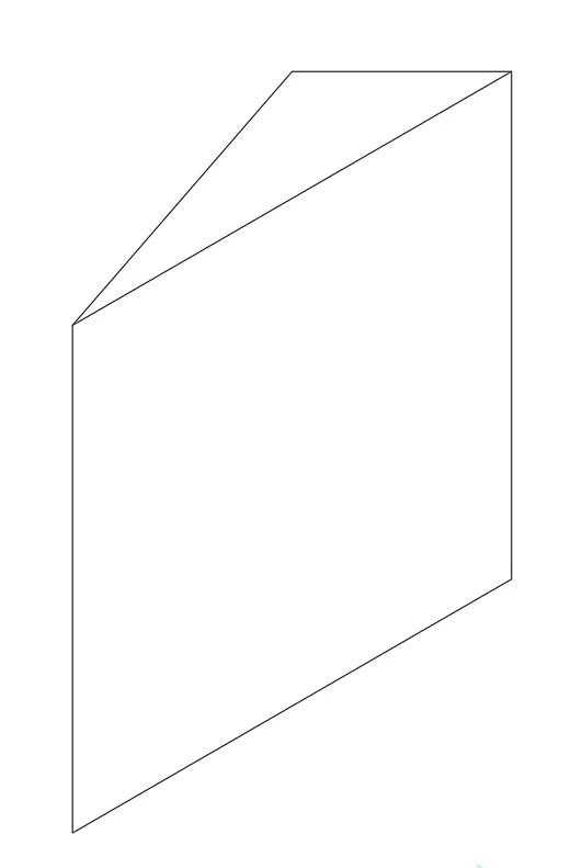
- Draw a vertical line of 12'6"
- Now connect the other side by side vertical lines with tip of the 12'6" line.
Again,
- From the mid of the lower horizonat line
- Draw a vertical line of 7'.
- Copy the 7' line on both the side at a distance of 1'6"
- Trim the extra lines
- Draw the Lintel of 3' at the 7' length.
Now,
- Make the draw a REGION.
- For this
- Type region and
- Select the sides you want to region
- Press enter
- Your region is created.
- Go to conceptual view .

Now,
- Presspull the above region
- Take thickness as 9".
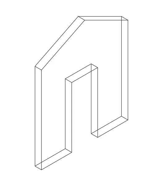
- Go to conceptual
- You get the following drawing.

Now, its time for dimension
- Type DST or dimensionstyle
- A dialogue box appears.
- Go to Modify
- Then go to Text
- Set the text height as 2.5".
- Similarly go to Arrow
- Set the arrow size as 2.5".
Now, its time for dimension
- Go ribbon tab
- CLick on Visualize
- Different tabs will open.
- Go to UCS.
- Click on the object UCS.
- And bring the UCS where u need to provide the dimension.
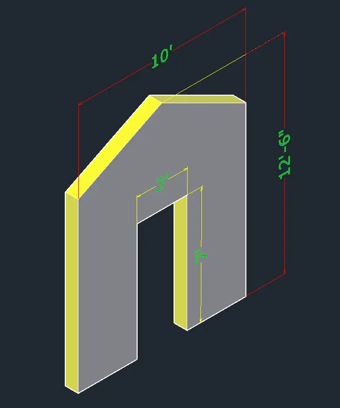
- So we have the following drawing after the dimensions.
Result: -
-------------------------------------------------------------------X---------------------------------------------------------------------------------------