Creating various 3D Models like Furniture, Footing, Girder, Column drop with panel and Gable Wall in AutoCad
Question no.1:
- AIM:
- To create a 3D Furniture element.
- To use proper view.
- Procedure:
- Open a new Autocadd file.
- Set the workplane in 3d view through workplan customization.
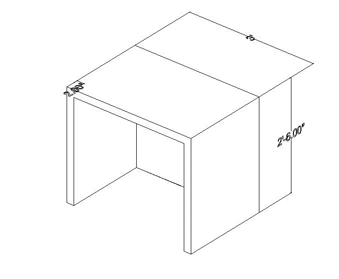
- The drawing to be drawn is furniture in a shape of a cuboid.
- The cuboid consist of a void.
- First a box sketched.
- The box is sketched by using a box tool in 3d modelling workplane.
- THe box tool is set on the workplane.
- The required cuboid is drawn with values 3'x2'6"x2'6"
- Where 3' is the length, 2'6" is the width and 2'6" is the depth of the box.
- Then the box is made to be void.
- To make void another box is created.
- This box is of size 2'8"x2'4"x2'4".
- Where 2'8" is the length, 2'4" are the width and the depth the new box.
- Then this new box is placed inside the first box such that it leaves 2" on 3 sides of the first box.
- Then subract tool is used.
- The subtract tool is used on the first box and then the new box.
- Where the new box makes the first box a void.
- The whole drawing is shown in a 2d wireframe view.
- The wire frame visible from behind are hide by 3dface tool.
- The 3dface was used on the top of the box and
- Then the hide command was used to hide the wireframes.
- Then the required furniture in the shape of a cuboid with the required void was created.
- Thus created furniture in shown below.
- RESULT:
- Thus the required furniture in the shape of a cuboid with the required void was created.
- Proper dimensions are used.
- The dimesions are made with corresonding views.
- The tools that are suitable for the 3dworkplane were used.
Question no.2:
- AIM:
- To create the 3d Model of an Isolated footing
- To use proper view.
- Procedure:
- Open a new Autocadd file.
- Set the workplane in 3d view through workplan customization.
- The drawing to be drawn is 3d Model of an Isolated footing
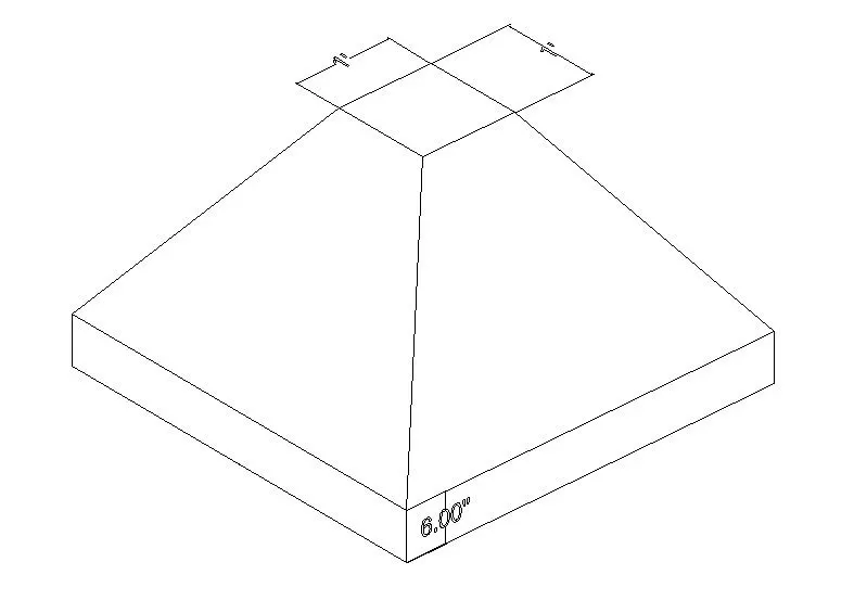
- The isolated footing is drawn as a box and a pyramid shape on the box
- First a box is sketched.
- The box to be drawn is of assumeddimensions.
- Thus the box has a thickness of 6"
- Then the box dimension given was 4'x4'.
- And the depth was given as 6".
- The a rec is creacted with a value of 1'x1'.
- The rec was created at a height of 2'
- Then the rec was made as a region.
- Then the loft tool was used to connect the box and the recctangle made as region to make a 3d object.
- Thus the box mounted with a pyramid was created.
- The drawing was created and viewd as 2d wireframe.
- Thus to hide the framed visible from the behind the tool 3dface and hide was used.
- The 3face command was used and then the top of the shape was sketched.
- And then the tool hide was used.
- Thus to hide the frames.
- And the shape is obtained in the 2d wireframe as a 3d object.
- Thus the 3d model of an isolated footing was created.
- RESULT:
- Thus the 3d model of an isolated footing was created.
- Proper dimensions are used.
- The dimesions are made with corresonding views.
- The tools that are suitable for the 3dworkplane were used.
Question no.3:
- AIM:
- To create the 3D view of the AASTHO Type Girder.
- To use proper view.
- Procedure:
- Open a new Autocadd file.
- Set the workplane in 3d view through workplan customization.
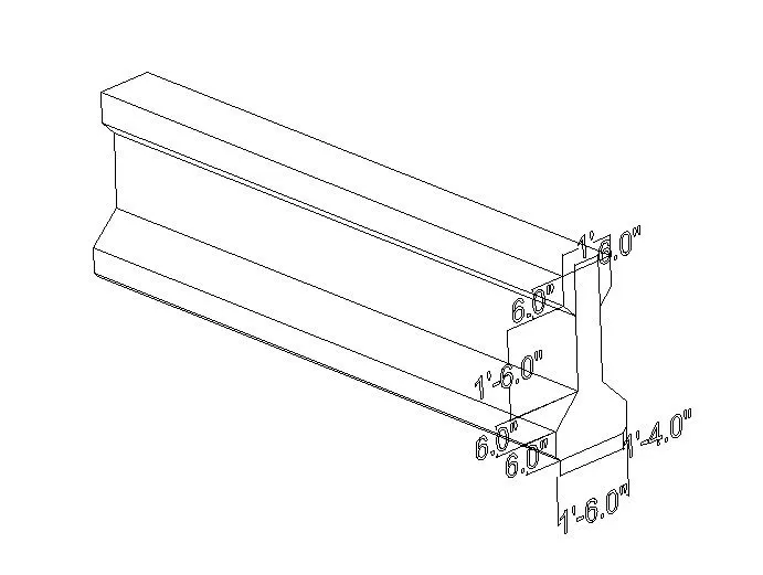
- The drawing to be drawn is the 3D view of the AASTHO Type Girder.
- The AASTHO type girder is similar to that of a I shape in 2d view.
- First trthe I shape was created by 2d top view in 3d modelling workplane.
- The I shape has the proper dimensions followed.
- Required chamfers were used in the edges of the I section.
- The total depth of teh I section is 3'.
- And the length of the I section is 1'
- The mid flange is sized to be 6".
- Then chamfers of required dimesion values were drafted.
- Then the I section is set in an isometric plane
- Then the 2d is made as region.
- Then the shape is extruded.
- The extrusion was taken to 10' as required depth.
- Thus the required 3d model of AASTHO type girder was created.
- RESULT:
- Thus the 3d model of AASTHO type girder was created.
- Proper dimensions are used.
- The dimesions are made with corresonding views.
- The tools that are suitable for the 3dworkplane were used.
Question no.4:
- AIM:
- To create a 3d Model of a drop column with panel.
- To use proper view.
- Procedure:
- Open a new Autocadd file.
- Set the workplane in 3d view through workplan customization.
- The drawing to be drawn is 3d Model of a drop column with panel.
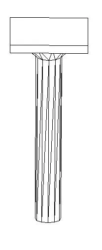
- The column with drop panel was sketched using a box and a cylinder shapes.
- Initially the panel is sketched.
- The panel is sketched using a bix structure.
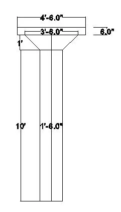
- The box created with a size of' 4'6"x4'6"x6"
- Where the 4'6" is the lengtha nd breadth and the 6" is the depth of the pANEL.
- Then the column is a cylinder.
- Hence to create a cylinder structure
- First a circle of 1'6"dia is drawn in the mid of the panel created.
- The circle is drawn at a distance of 1' from the panel.
- The cylinder and the panel is connected by a loft.
- The cicle for loft created with a size of 3'6" diameter.
- Then the circles are lofted after making them as a region.
- The main cyilneder is presspulled to a distance of 10'
- Which represents the depth of the column as 10'
- Thus the required column with drop panel was created.
- The created column with drop panel is shown below.
- It is shown as both 3D mode and The top view as 2d.
- RESULT:
- Thus the required column with drop panel was created.
- Proper dimensions are used.
- The dimesions are made with corresonding views.
- The tools that are suitable for the 3dworkplane were used.
Question no.5:
- AIM:
- To create the 3d model of a wall.
- To use proper view.
- Procedure:
- Open a new Autocadd file.
- Set the workplane in 3d view through workplan customization.
- The drawing to be drawn is 3d model of a wall.
- Initially a rectangular block was created.
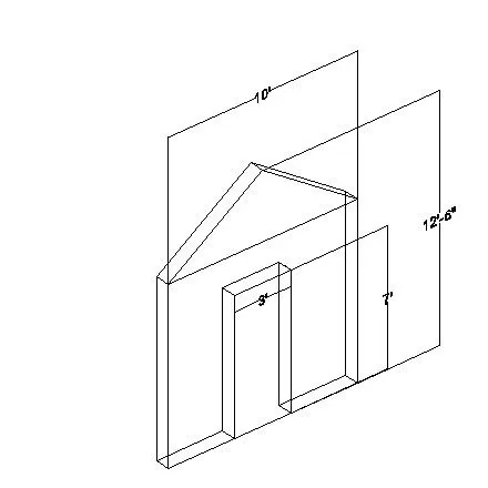
- In this drawing the modle contains the wall with a pitch on its top.
- And a door opening left in its sill.
- The rectangular block created here is for the wall.
- The wall of size 9" is created using a 3d box for a height of 12'6"
- And a width od 10'.
- Then a void is cretaed in the box.
- The void is for the door opening.
- The required door opening is of size 3'x7'.
- Where its head height is 7' and the door width gap is 3' along with a panel space.
- To create this void.
- A box of size 3'x 7' was made and fitted in the wall at the required position.
- Then the subtract tool was used to subtract the newly created box from the wall.
- Then the pitch in the top of the wall to be created.
- To create it the centre point at the top of the walll is chosen.
- And a 45 adn 135 degree line is drawn from the centre of the wall top.
- Then the extra part is sliced off.
- By creatinga a cone shape of required size and subtraccting with teh top.
- Thus the wall with pitched top and a door openig was created.
- The drafted 3d model of the wall is shown below.
- RESULT:
- Thus the wall with pitched top and a door openig was created.
- Proper dimensions are used.
- The dimesions are made with corresonding views.
- The tools that are suitable for the 3dworkplane were used.