Creating various 3D Models like Furniture, Footing, Girder, Column drop with panel and Gable Wall in AutoCad
1. Create a 3D Furniture element as shown in the Figure. Assume dimensions which are missing.
Ans1:
AIM: To create a 3D furniture element as given in the figure and providing dimensions for same using various 3D drawing tools.
PROCEDURE:
- Open a new drawing.
- Set the scale to imperial and Engineering units
- Change the settings to 3D Modelling
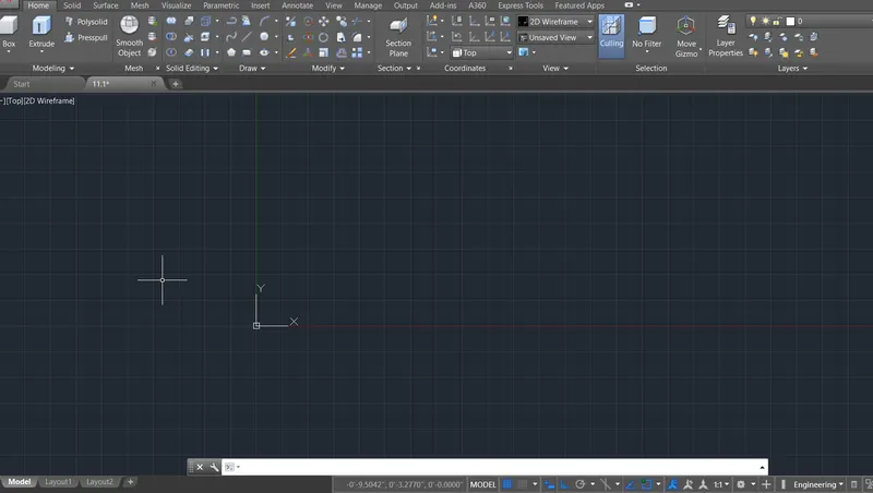
- Select 2D Wireframe or Hidden and Top view initially
- Draw the base of the furniture element with given dimensions and assume depth 0f 2 ft.
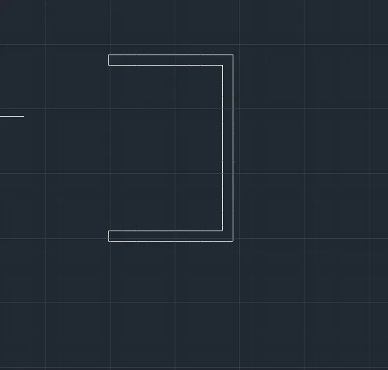
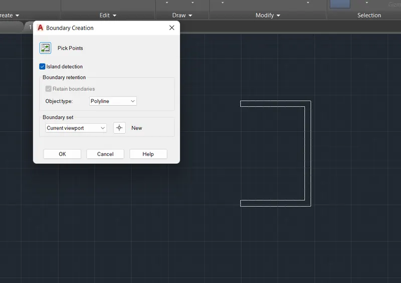
- Convert the drawing to region by Boundary command or Region command
- Change the view to SW Isometric view.
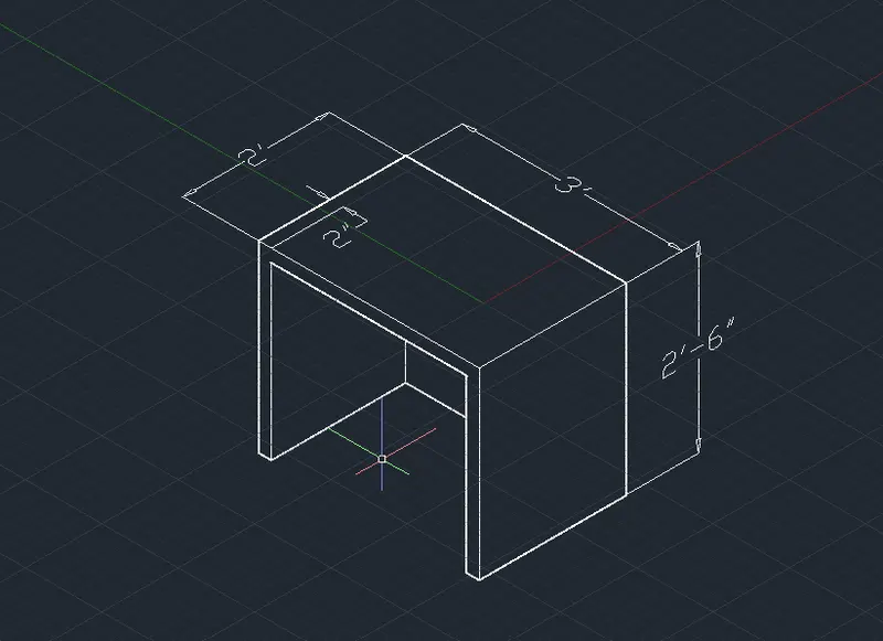
- Extrude the sides of furniture element by height of 2'6"
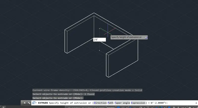
- Draw a rectangle for the top of furniture element inside the extruded furniture sides at top
- Extrude the rectangle to height of 2" downwards to create thickness of top.
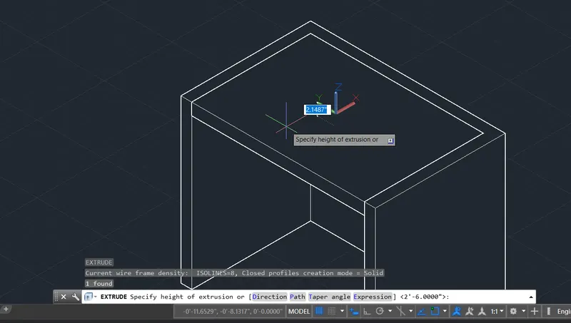
- Select the sides and the top elements of furniture and join using Union command
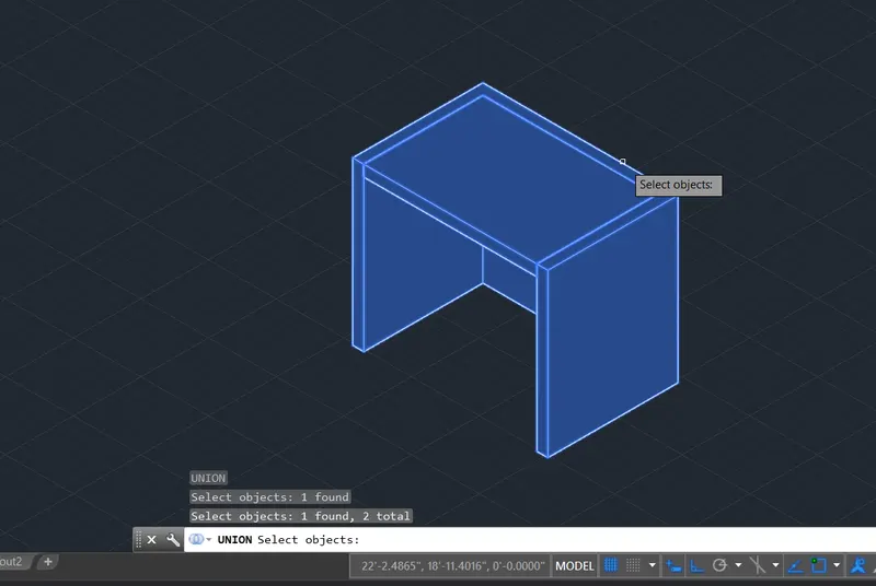
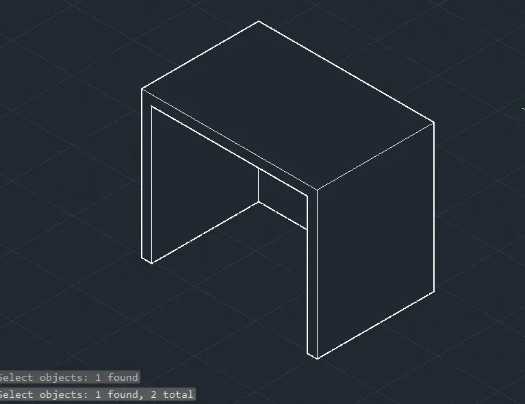
- Thus the required furniture element drawing is ready as per the given figure.
- Move the UCS to the face of the element for providing dimensions in for the required face plane.
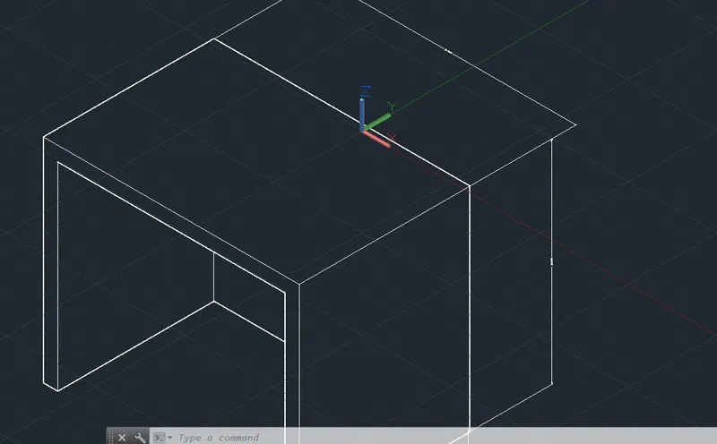
- The final furniture element drawing along with the dimensions as per given figure is completed as shown below.
- The layout drawing of the furniture element is shown below.
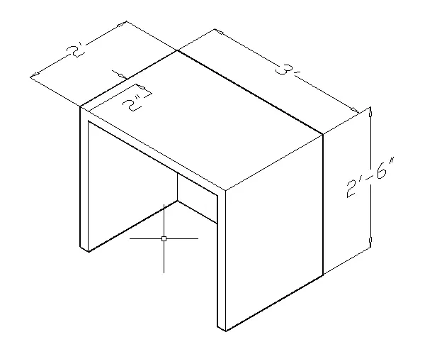
CONCLUSION: Thus we have created a 3D drawing for the furniture element given in the figure using various 3D drawing tools and provided the dimesions for the same.
2. Create the 3d Model of an Isolated footing as shown in Figure.
Ans2:
AIM: To create the 3D Model of an Isolated footing as per the given figure and providing the dimensions for the same using various 3D drawing tools.
PROCEDURE:
- Open a new drawing with Imperial scale and Engineering units.
- Change the settings to 3D modelling
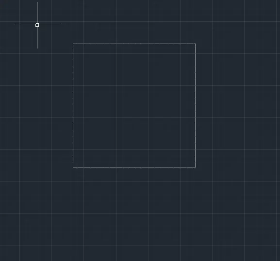
- In 2D wireframe or hidden and Top view draw a square assuming 4' size of footing using rectangle command.
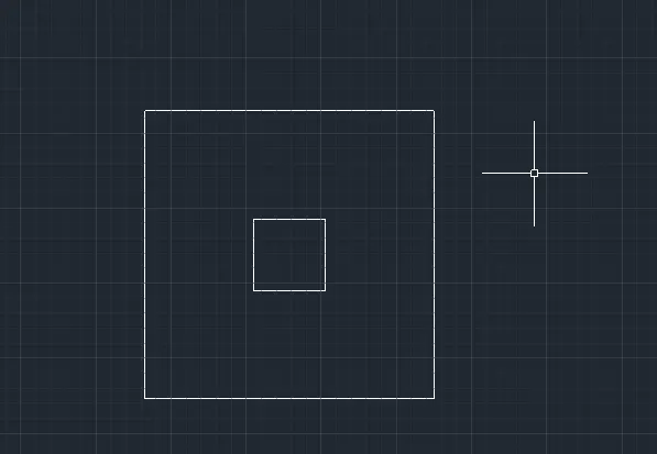
- Draw a square of 1' side for top of trapezoidal part of footing and place center on the center of bigger square
- Change the view to SW isometric view
- Move the small square by 2' for the height of trapezoidal part
- Use Loft command to create the trapezoidal part of the footing as shown below
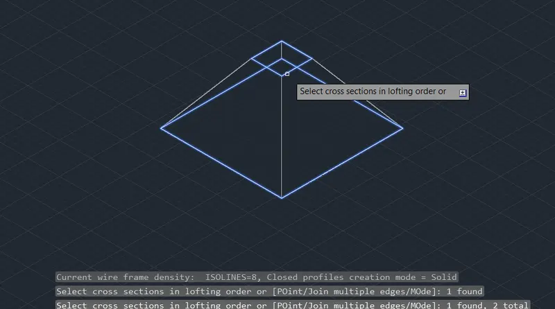
- Thus trapezoidal part of footing is formed as shown below
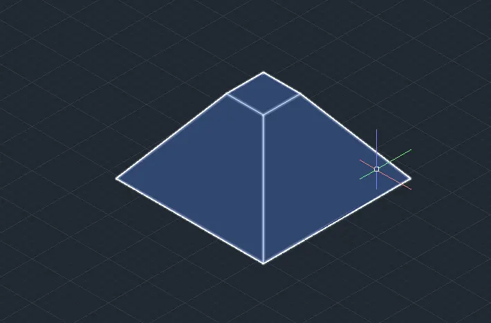
- Draw one more square of 4' for the base cuboid of footing
- Extrude the square by 6" height for forming the base of footing
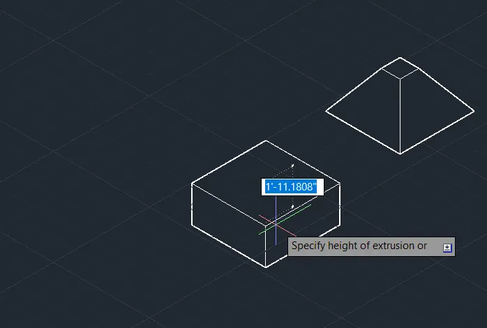
- Place the trapezoidal part of footing on the cuboidal part of footing
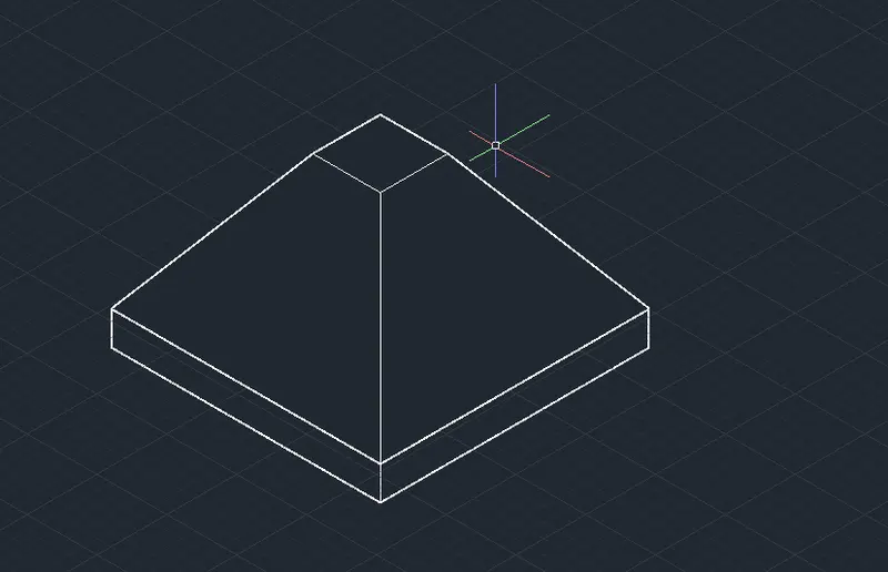
- By using the Union command join the two parts of the footings
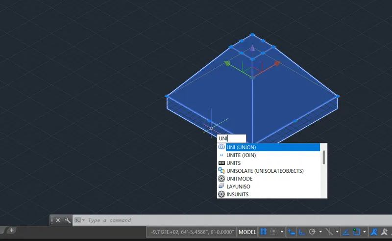
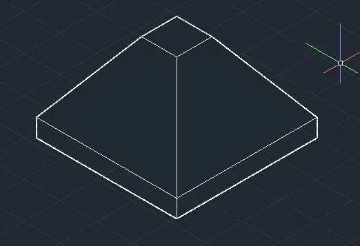
- Thus the required 3D model of isolated footing is created as shown below.
- By shifting the UCS to the required planes of the footing the dimensions are provided as shown below.
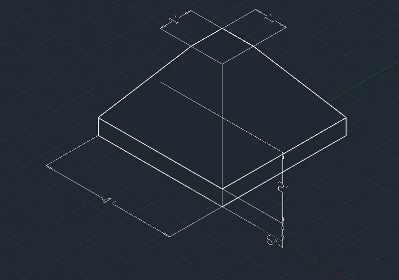
CONCLUSION: Thus using various tools of 3D drawing we have created a 3D model of the given Isolated footing and provided the dimensions.
3. Create the 3D view of the AASTHO Type Girder.
Ans3:
AIM: To create the 3D view of the AASTHO Type Girder using various drawing tools in 3D drawing.
PROCEDURE:
- Create a drawing sheet of imperial scale and Engineering units and select the 3D modelling setting with TOP view and Hidden or 2D wireframe initially.
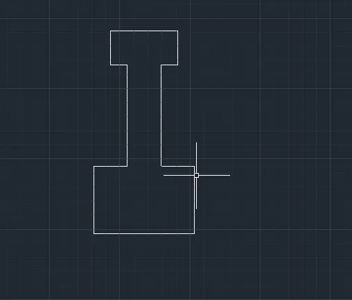
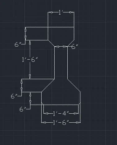
- Draw the girder drawing using the line command as per the dimensions given in the figure
- Provide the chamfers as per the figure to form the shape of girder
- Check the dimensions after completing the figure as shown below
- Change the view to SW Isometric view.
- Extrude the section of the Girder to 10' length as shown in figure.
- Dimensions are provided by shifting the UCS to required face planes.
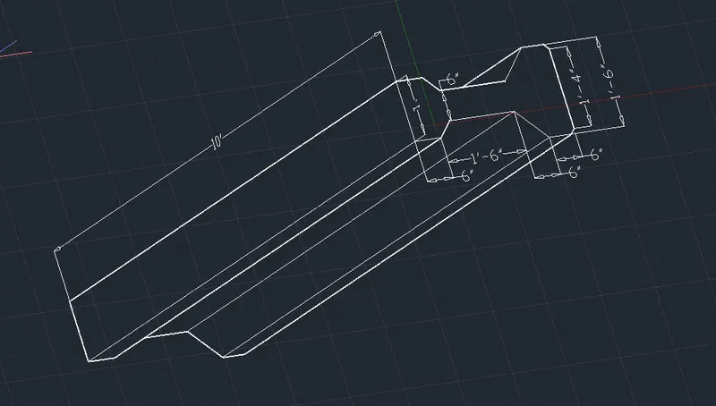
- The final 3D view of the AASHTO Type Girder is created as shown below
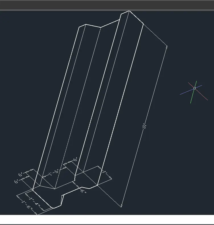
CONCLUSION: Thus we have created the 3D view of the AASHTO Type Girder using various 3D drawing tools and provided the dimensions for the same.
4. Create a 3d Model of a drop column with panel as shown in section and isometric view.
Ans4.
AIM: To create a 3D Model of a drop column with panel as per the given section and isometric view.
PROCEDURE:
- Create a drawing sheet of imperial scale and Engineering units and select the 3D modelling setting with TOP view and Hidden or 2D wireframe initially.
- Draw a Square of 4'6" and with same center draw a circle of 3'6" and 1'6"
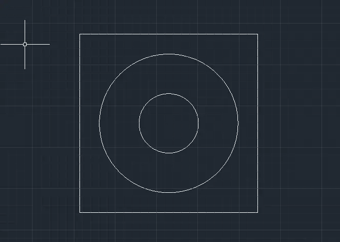
- Change the view to SW Isometric view
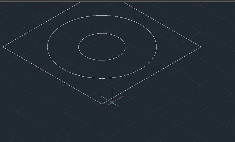
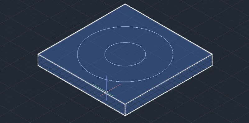
- Extrude the square for 6" for thickness of square panel
- Move the small circle by 1'6"
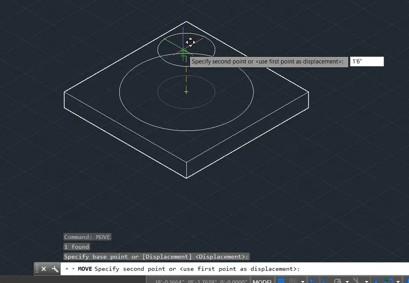
- Create the conical surface by using Loft command and connecting two circles.
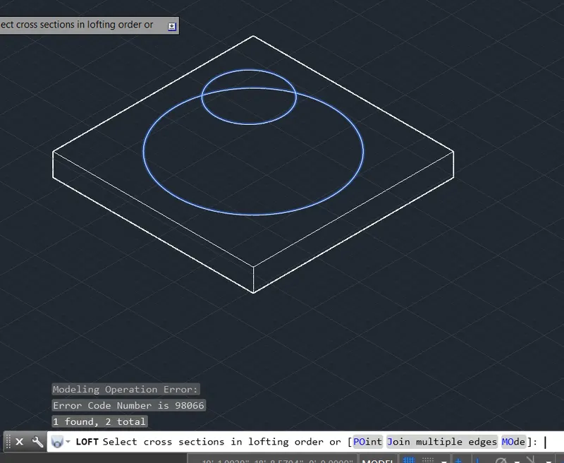
- The conical surface forme is as below
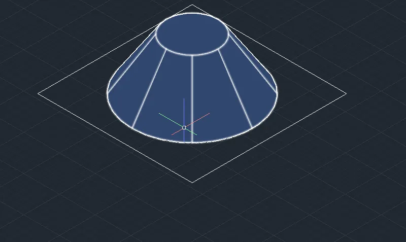
- Draw a circle of 1'6" on top of conical surface and extrude the circle to form a 10' column
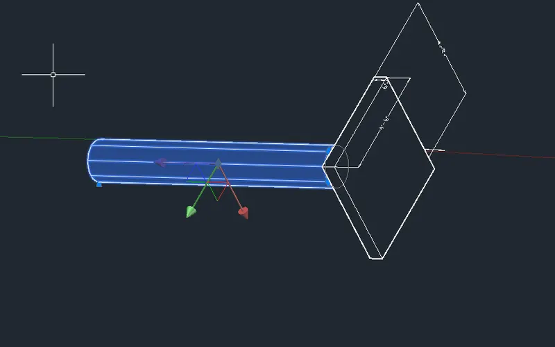
- The final model of column with drop panels are shown in different views in screenshots below.
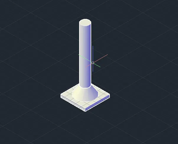
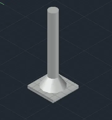
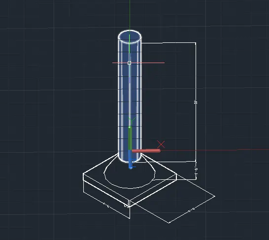
- The 3D model as per the isometric view in the figure is shown below.
CONCLUSION: Thus we have created a 3D model of the drop column with panel as per the given section and isometric view using various tools of 3D drawing.
5. Create the 3d model of a wall as shown in Figure. Consider wall thickness as 9”.
Ans5:
AIM: To create the 3D model of a wall as per the given figure and providing the dimensions.
PROCEDURE:
- Create a drawing sheet of imperial scale and Engineering units and select the 3D modelling setting with TOP view and Hidden or 2D wireframe initially.
- Draw the front view of the wall as per the given dimensions in the figure.
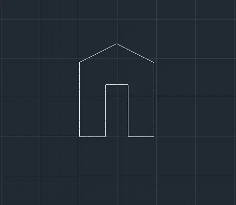
- Using the Region command join the lines of the drawing.
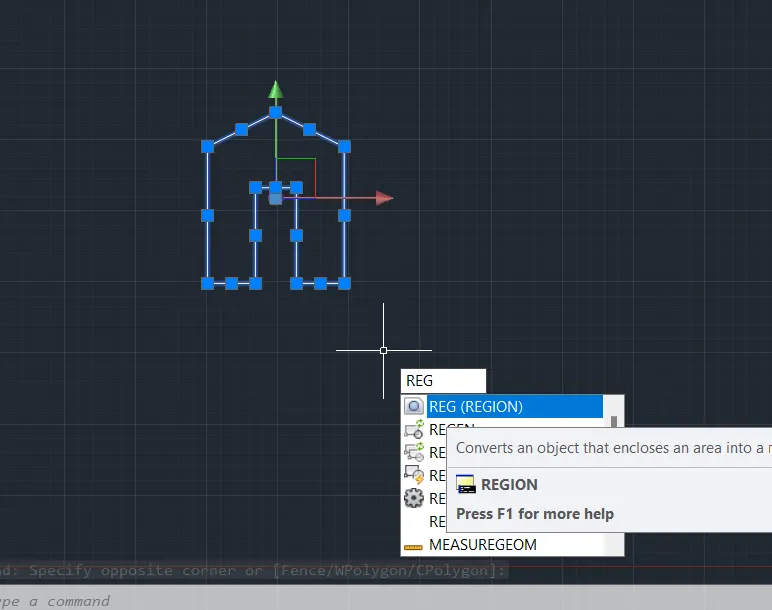
- Change the view to SW isometric view
- Using 3D rotate command rotate the wall by 90degrees for the vertical wall view.
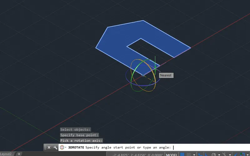
- The vertical wall in Isometric view is shown below.
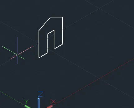
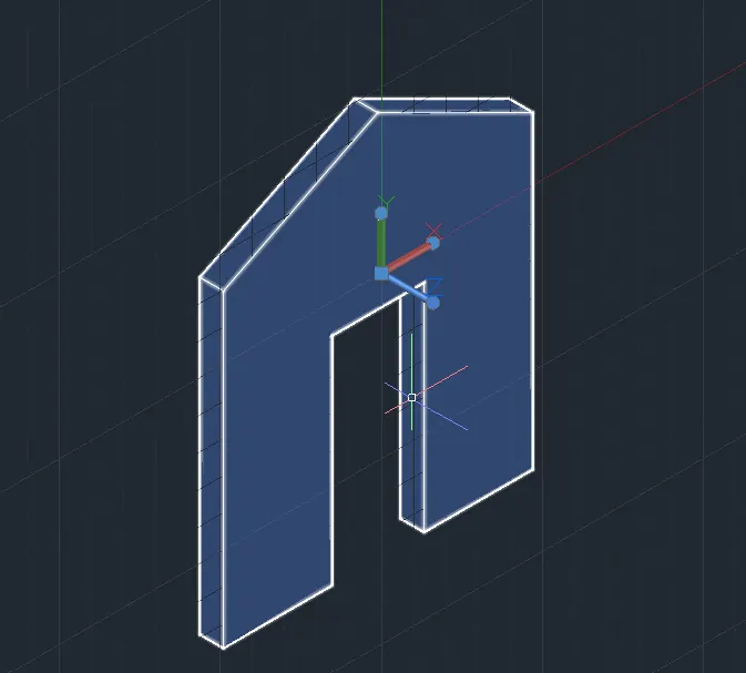
- Extrude the wall surface by 9" for thickness of wall
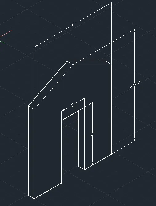
- By moving the UCS to required planes of the wall the dimensions are provided as per the given figure.
CONCLUSION: Thus we have created the 3D model of a wall given in the figure using various 3D tools and provided the dimensions.