Creating various 3D Models like Furniture, Footing, Girder, Column drop with panel and Gable Wall in AutoCad
Aim:
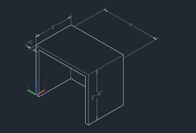
To create a 3D furniture as shown in the figure.
Introduction:
Create the profile of the furniture by using line tool and relative rectangular coordinate system. Create the surface of the profile by using 'Region' command and create the furniture into 3D object by using 'Extrude' command.
Procedure:
- Open Autocad software and open new drawing With imperial units.
- Set the units as engineering and precision as 0'-0''
- Switch the work space to 3D modeling and set the view as South-West isometric.
- Use line tool specify the first point as 0,0,0
- By using relative rectangular coordinate system enter the next point @0,0,2'6''
- Enter the upcoming next points by using relative coordinate system @0,-3',0 @0,0,-2'6'' @0,-2'',0 @0,0,2'4'' @0,2'8'',0 @0,0,-2'4'' and @0,2'',0
- The face profile of the table is created.
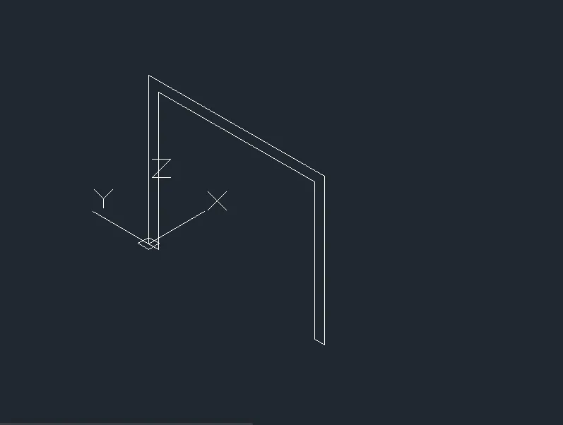
- Use region command to create the surface of the object.
- Type 'Region' in the command prompt.
- Select object option and select the object to create the surface.
- Change the visuval style to conceptual.
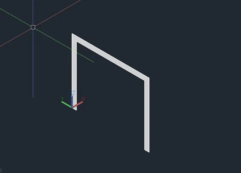
- Extrude the created surface in the x-axis at a distance of 2'
- Type 'Extrude' in the command prompt.
- Select the object to extrude the surface.
- Enter the extrude distance as 2'
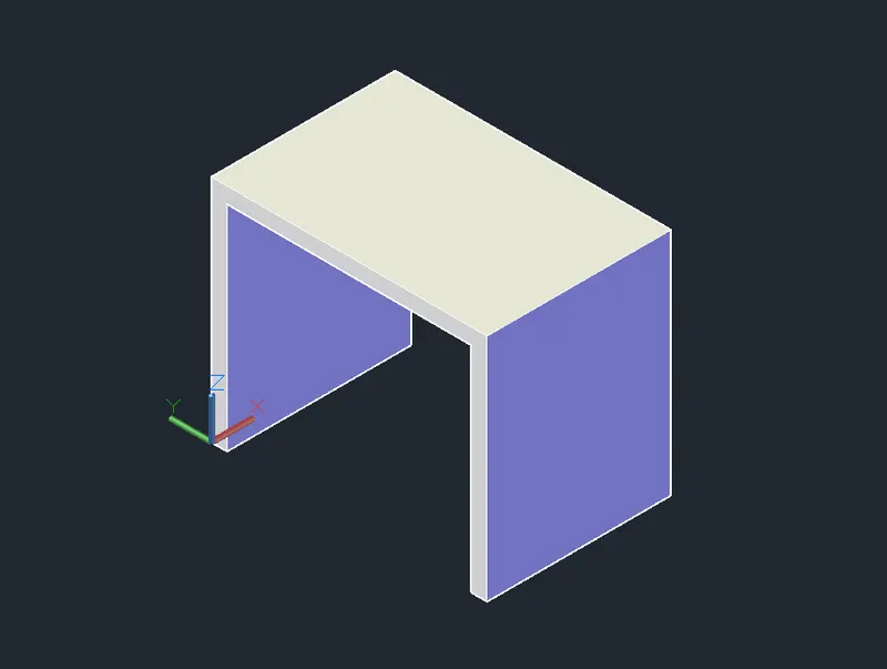
- Change the view to South-East isometric.
- Create a rectangle of size 2'-8'',0'-2'' at the base of the object created.
- Make the rectangle as surface by using region command.
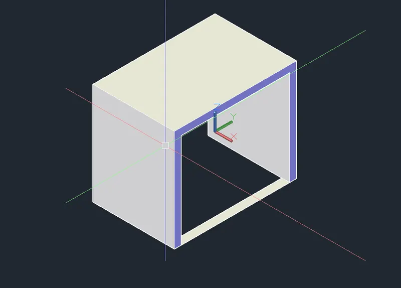
- Extrude the surface created in the rectangle at a height of 2'-4''
- Set the view to South-West isometric.
- Change the visual style to hidden and create the dimensions by using 'dimlin' command.
Result:
The 3D furniture model is created by as shown in the figure and the missing dimensions are assumed.
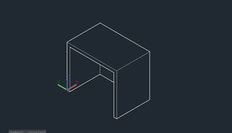
Hidden visual style.
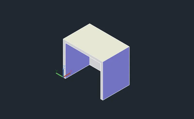
Conceptual visual style.
Aim:
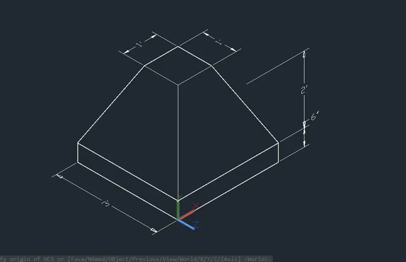
To create a 3D model of isolated footing as shown in the figure.
Introduction:
The isolated footing is created by the box and pyramid tools and dimension it to check the measurements. Relative rectangular coordinate system and the UCS command is used. Assume the size of the footing is 3'X3'
Procedure:
- Open Autocad software and open new drawing With imperial units.
- Set the units as engineering and precision as 0'-0''
- Switch the work space to 3D modeling and set the view as South-West isometric.
- Creatre a box using box tool under the solid tab.
- Specify the first corner point of the box as 0,0,0 and other corner point @3',3',0
- Specify the height as 6''
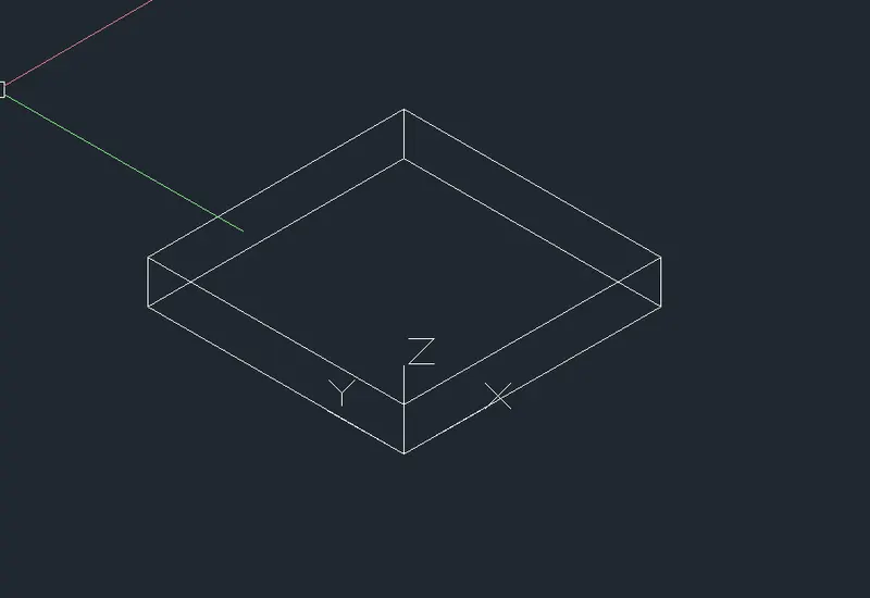
- Type 'UCS' in the command prompt.
- Select object and place the ucs at the top of the box.
- Use pyrsmid tool, create pyramid at the top of the box.
- Specify the first point at the top first corner of the box and second point at the top second corner point of the box.
- Select the 'Top radius' option in the command prompt.
- Enter the top radius as 6''
- Specify the height as 2'
- Set the visual style as hidden.
- Change the visual style to hidden and create the dimensions by using 'dimlin' command.
Result:
The 3D model of isolated footing is created as shown in the figure.
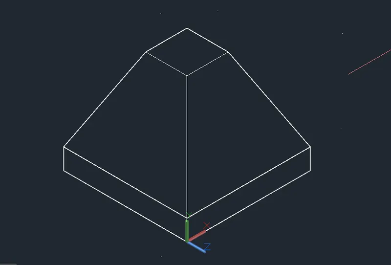
Hidden visual style.
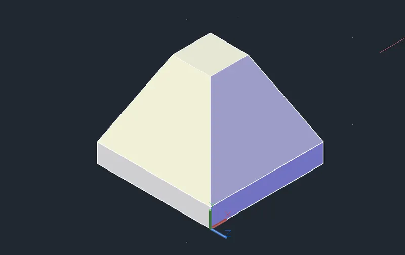
Conceptual visual style.
Aim:
TO create a 3D view of AASHTO type grider.
Introduction:
The AASHTO type grider is created by create the face profile of the grider and create surface of the profile and extrude at a distance of 10'
Procedure:
- Open Autocad software and open new drawing With imperial units.
- Set the units as engineering and precision as 0'-0''
- Switch the work space to 3D modeling and set the view as South-West isometric.
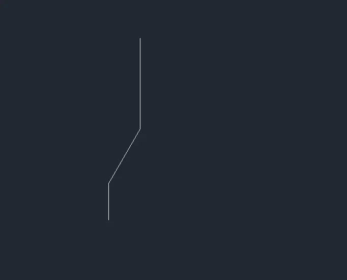
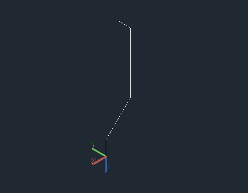
- Create line specify the first point as 0,0,0
- BY using relative rectangular coordinate system specify the other points to create the profile.
- Next point @0,0,6 @6<0,6 and @0,0,1'-3''
- Change the UCS, type 'UCS' in the command prompt and select Z-axis.
- Specify point om positive protion of Z-axis as the negative side of the Z-axis.
- Create line by specify the first point at the last point of the line created and enter the next point @3<0,-3
- Change the UCS to UCS world.
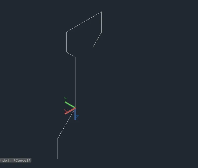
- Continue creating the line @0,0,6'' @1',0,0 and 0,0,-6
- Change the UCS, type 'UCS' in the command prompt and select Z-axis.
- Specify point om positive protion of Z-axis as the negative side of the Z-axis.
- Create line by specify the first point at the last point of the line created and enter the next point @3<0,3
- Change the UCS to UCS world.
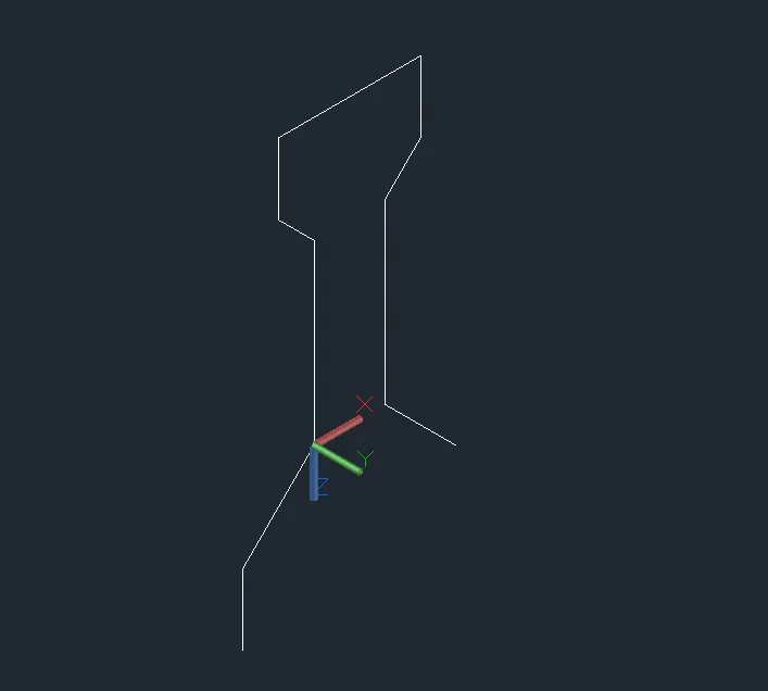
- Create line at the first point as the last created line last point and next point @0,0,-1'3''
- Change the UCS by typics 'UCS' in the command prompt.
- Select X and enter the rotation angle as 90 deg.
- Continue creating line next point @6<0,6
- Change the UCS to UCS world.
- Continue creating the line enter the next point @0,0,6 and @-1'-6'',0,0
- Chamfer the created face at the bottom sides both corners at the first and second distance 1''
- Type 'chamfer' in the command prompt.
- Select the multiple option to create the chamfer.
- Use region command select the whole object created and create the surface.
- Change the visual style as conceptual.
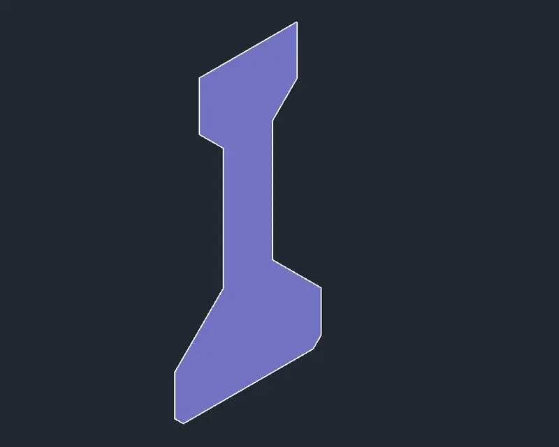
- Extrude teh surface towards the Y-Axis at a distance of 10'
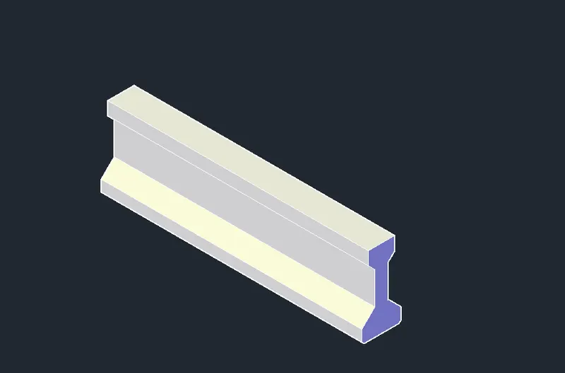
- Change the visual style as hidden.
- Create dimensions to the model.
- Change the UCS by typing 'UCS' in the command prompt.
- Select X-axis and specify the rotation angle as 90 deg.
- Use 'dimlin' command to dimension the model.
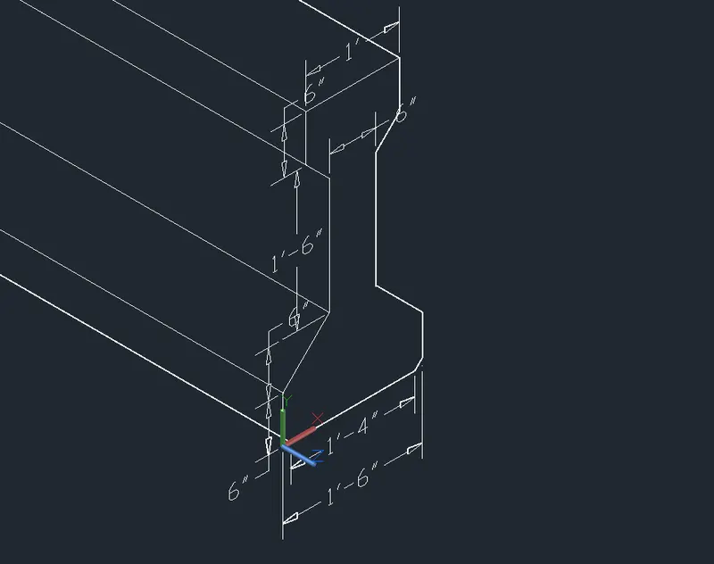
Result:
The 3D model of the ASSHTO type grider is created.
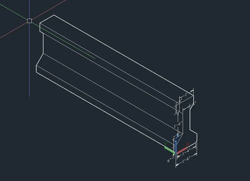
Hidden visual style.
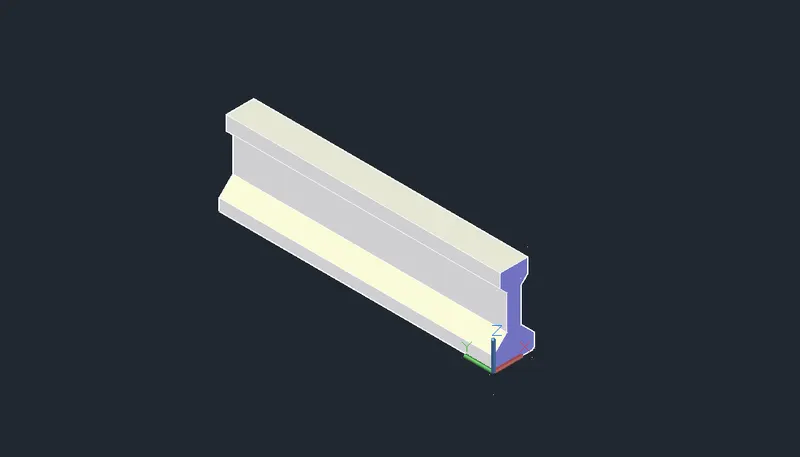
Conceptual visual style.
Aim:
To create the 3D model of the drop column with panel as shown in the section and isometric.
Introduction:
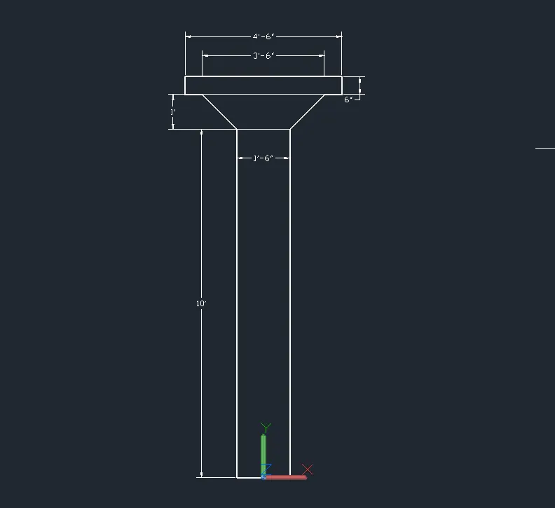
The 3D model of drop column with panel is created by using the cylinder tool, cone tool and rectangle tool. The height of the column is 10', column capital is 1' and the drop panel is 6'' depth. The radius of the column is 9'' and the drop panel size is 4'-6'' sq.
Procedure:
- Open Autocad software and open new drawing With imperial units.
- Set the units as engineering and precision as 0'-0''
- Switch the work space to 3D modeling and set the view as South-West isometric.
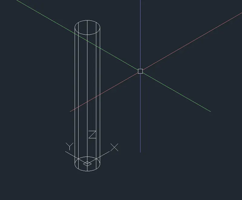
- Create a cylinder.
- Specify the center point of the cylinder as 0,0,0 and radius 9'' at a height of 10'
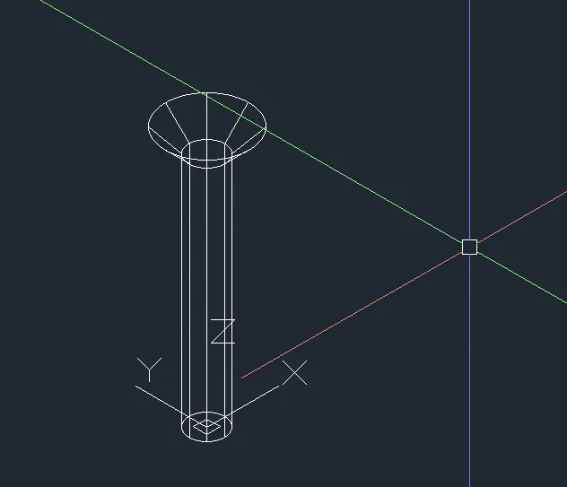
- Create a cone with specify the center point of the cone at center top of the cylinder.
- Specify the base radius as 9''
- Choose top radius option.
- Specify the to radius as 1'-9'' and specify the height as 1'
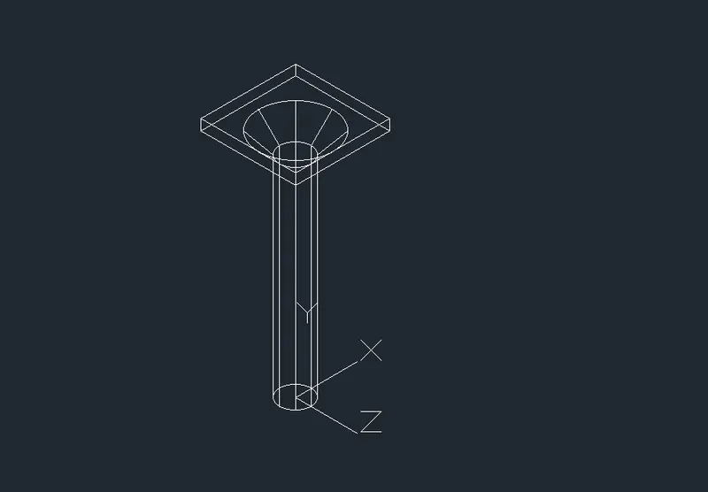
- Create rectangle, specify the first corner point at the top center of the cone.
- Specify the other corner point @4'6'',4'6'',0
- Use region command create a surface of the rectangle.
- Extrude the rectangle at a height of 6''
- Change the UCS and check the dimensions by creating dimensions in the model.
- Change to front view.
- Change the UCS select X and specify the rotation angle as 90 deg.
Result:
The 3d model of the drop column with pannel is created.
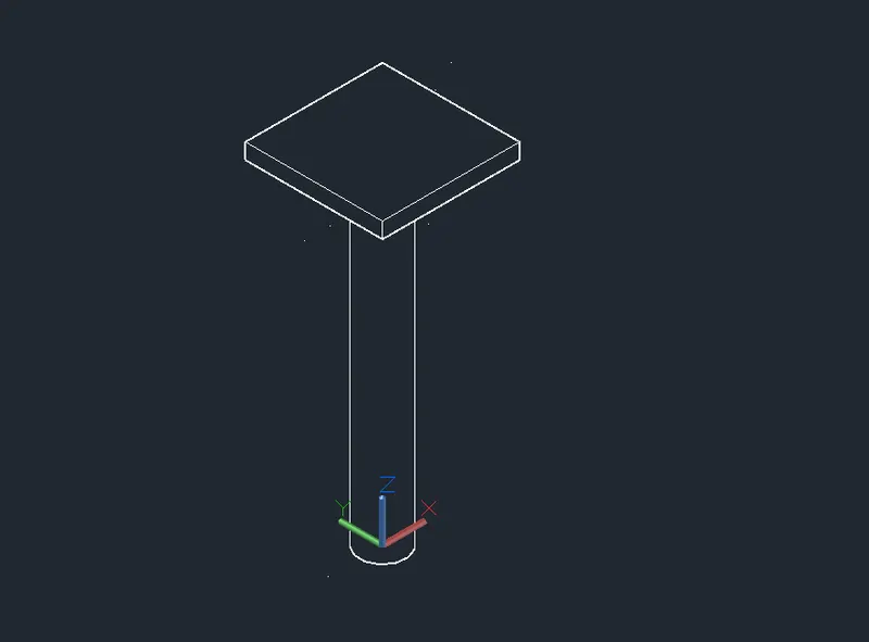
Hidden visual style.
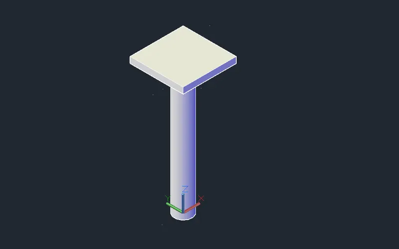
Conceptual visual style.
Aim:
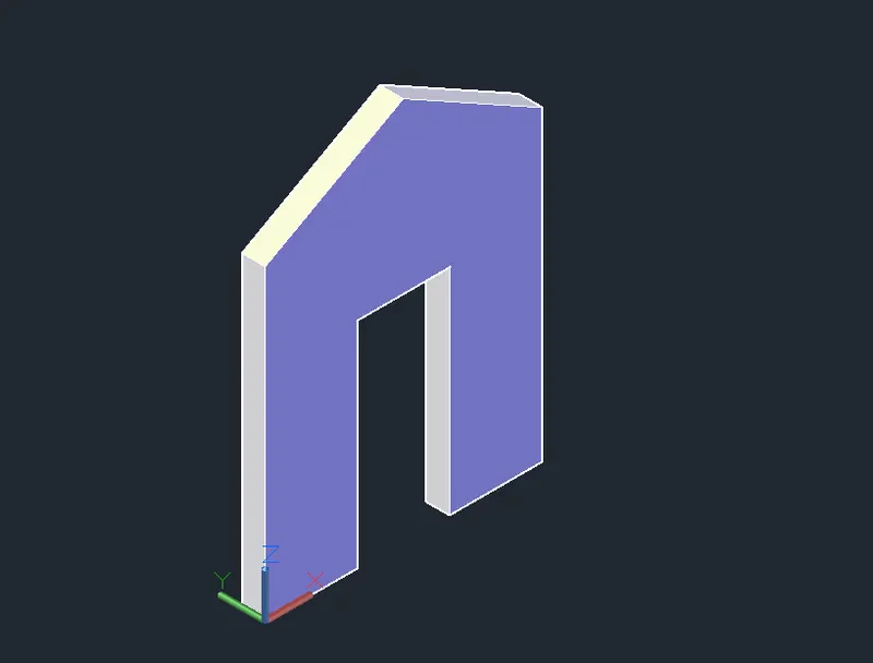
To create the 3D model of a wall as shown in the figure.
Introduction:
The 3D model of the wall is created by create the face profile of the wall and create surface to it and extrude operation.
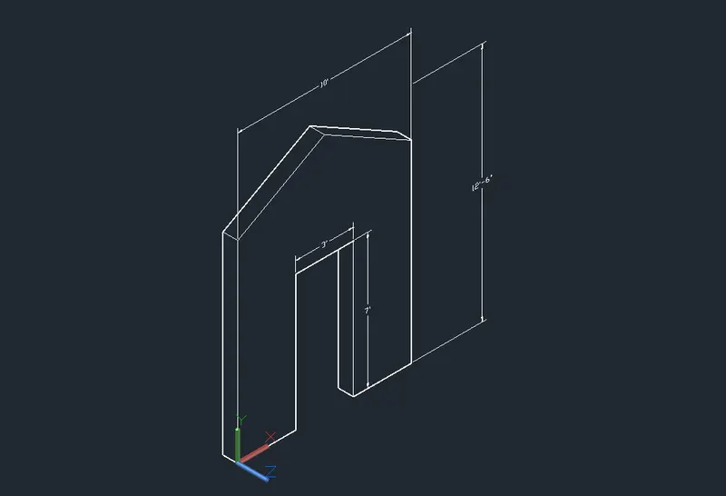
The length of the wall is 10' , width of the wall is 9'' and the height of the wall is 12'-6''. The door opening size is 3'X7'
Procedure:
- Open Autocad software and open new drawing With imperial units.
- Set the units as engineering and precision as 0'-0''
- Switch the work space to 3D modeling and set the view as South-West isometric.
- Use line tool to create a line, specify the first point of the line as 0,0,0
- Enter the next point of the line @3'4'',0,0
- Enter the following points to create the face profile of the wall.
- @0,0,7' @3',0,0 @0,0,-7' @3',0,0 and @0,0,10'
- Create a line, specify the first point as 0,0,0 and next point @0,0,10'
- Create a reference line to joint the top two end points of the profile.
- Create a line in the z-axis from the mid point of the created reference line at a distance of 2'6''. This is also a reference line.
- Create a line in the left top end point of the line and joint it to the end point of the reference line.
- Follow the same procedure to create a slope line in the other side.
- Erase the two reference line created.
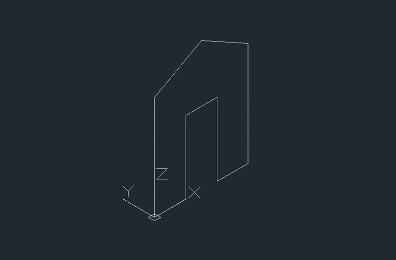
- Use region command.
- Create surface as the created wall face.
- Type 'Region' in the command prompt.
- Select object in the command prompt and select the whole object.
- Switch the visual style to conceptual.
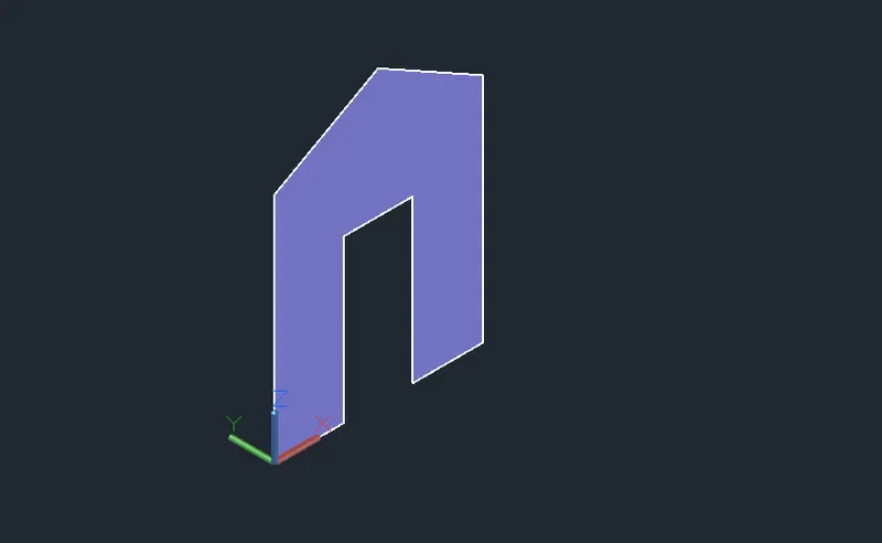
- Extrude the surface at a distance of 9'' in the Y-axis direction.
- Type 'Extrude' in the command prompt.
- Select the surface and enter the extrude distance as 9''
- Change the UCS and check the dimensions by creating dimensions in the model.
- Change to front view.
- Change the UCS select X and specify the rotation angle as 90 deg.
Result:
The 3D model of the wall is created.
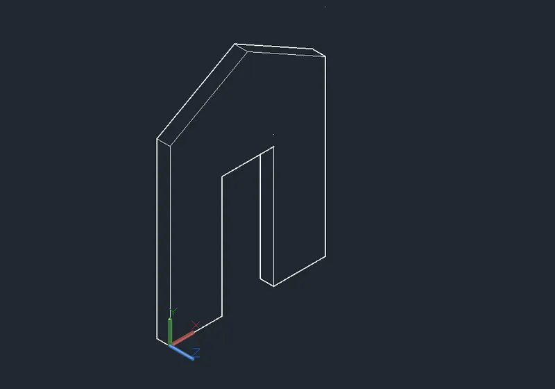
Hidden visual style.
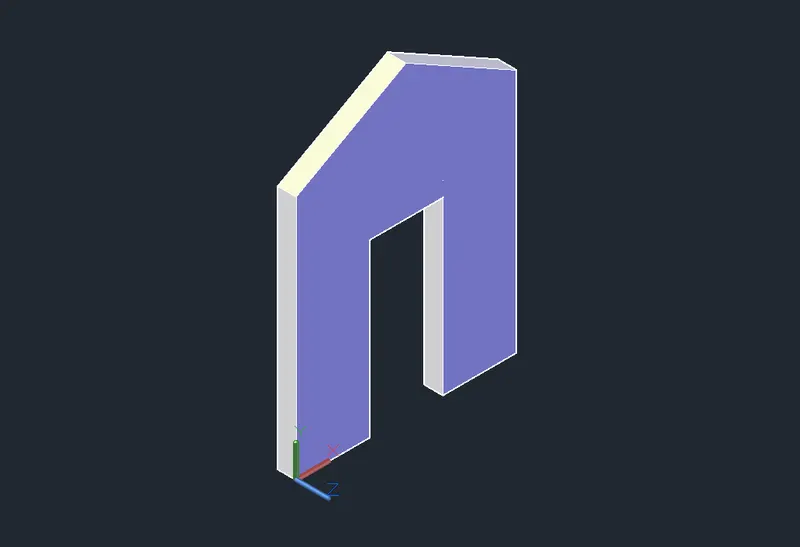
Conceptual visual style.