Creating various 3D Models like Furniture, Footing, Girder, Column drop with panel and Gable Wall in AutoCad
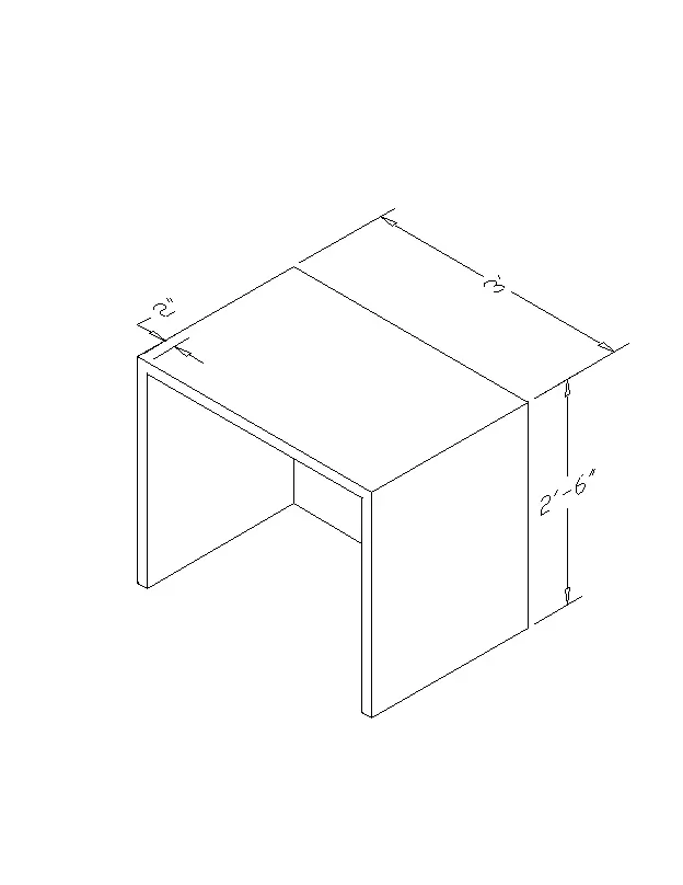
1. Create a 3D Furniture element as shown in the Figure. Assume dimensions that are missing
Aim:
To Create a 3D furniture element as shown in the figure by using AutoCAD 3D software.
Introduction:
Various commands used:
- QNEW command
- UN command
- Box command
- Rectangle command
- Extrude command
- SUBTRACT command
- DIMLIN command
- 3DO command
- UCS command
Procedure:
step-1: Open AutoCAD software
step-2: Enter the QNEW command to start a new window
step-3: Enter the UN command to set the unit style and fraction value
step-4: Enter the LIMITS command to set the size of the sheet
step-5: Select 3D modeling from right bottom corner tab
step-6: Type "REC" to invoke rectangle tool to plot the "0',3',2'6"" values
step-7: Type "REC" to draw the inner rectangle of the existing one with the offset value of 2"
step-8: Type "REG" to invoke the region tool and select the objects
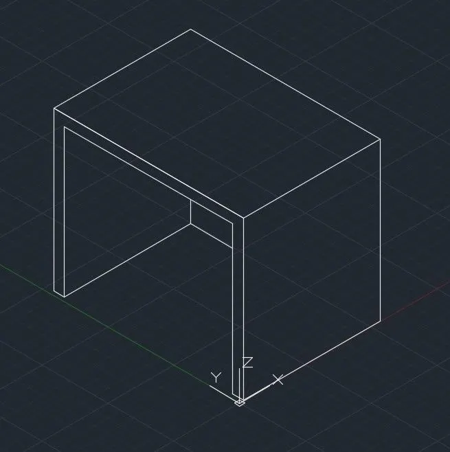
step-9: Type "EXT" to extrude the outer rectangle with 2' in the direction of the "X" axis
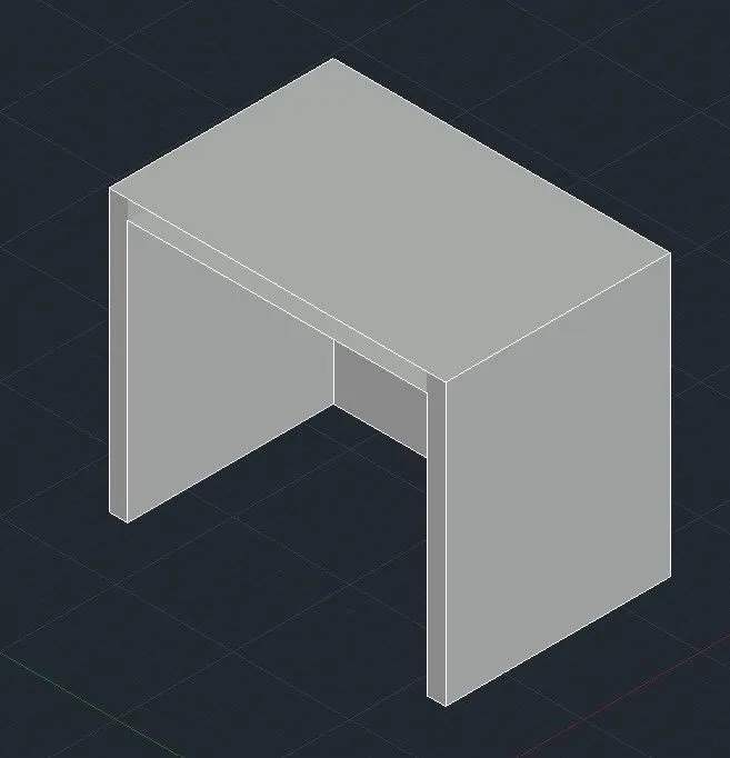
step-10: Type "SUBTRACT" to subtract the inner rectangle.
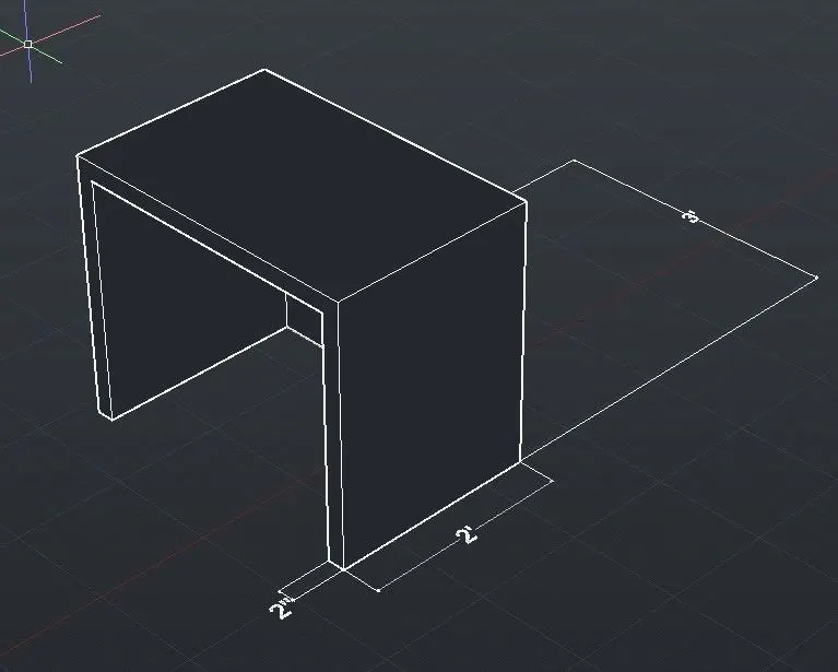
step-13: Type "DIMLIN" to mark the all dimensions in the drawing
Result:
Finally, we have furniture drawing by using Auto CAD 3D.
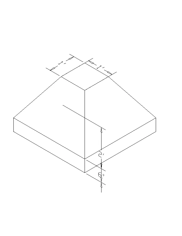
2. Create the 3d Model of an Isolated footing as shown in Figure.
AIM:
To create a 3D model of Isolated footing as shown in the figure by using Auto CAD
Introduction:
Various commands used:
- QNEW command
- UN command
- Box command
- Rectangle command
- Extrude command
- SUBTRACT command
- DIMLIN command
- 3DO command
- UCS command
Procedure:
step-1: Open Auto CAD software
step-2: Enter the QNEW command to start a new window
step-3: Enter the UN command to set the unit style and fraction value
step-4: Enter the LIMITS command to set the size of the sheet
step-5: Select 3D modeling from the right bottom corner tab
step-6: Enter the "REC" command to plot a rectangle with the size of 3',3'
step-7: Enter the "REC" command to plot an inner rectangle with the size of 1',1'
step-8: Type the "MOVE" command and select the inner rectangle and move 2' in the direction of the "Z" axis
step-9: Type the "L" line tool to connect both the inner and outer rectangle
step-10: TYpe "REG" to select both rectangles and make region on this
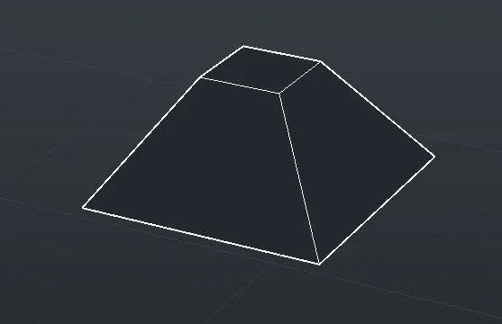
step-11: TYpe "3DF" to invoke the 3DFACE tool and select the all corners of the objects to make the region
step-12: Select the Push/Pull tool from the ribbon tab and select the bottom of the rectangle and pull towards the negative "Z" axis at 6"
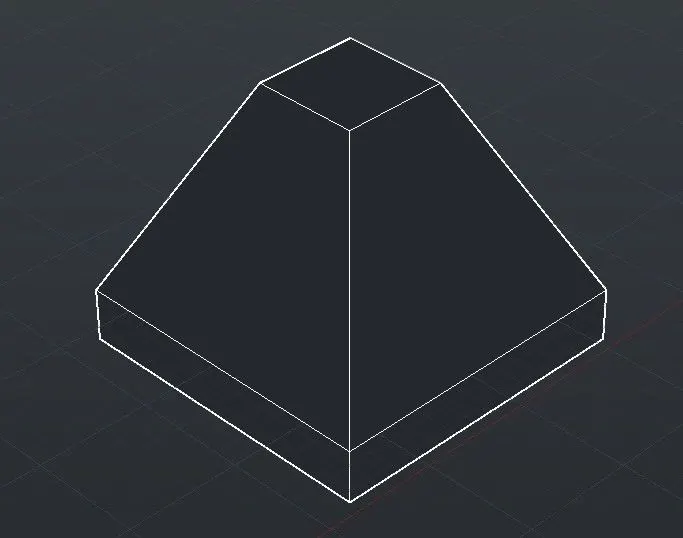
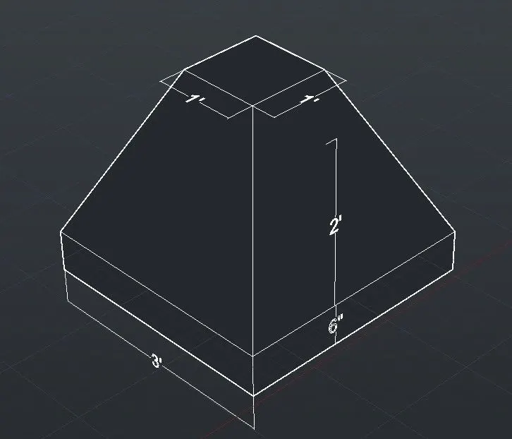
step-13: Type the "DIMLIN" tool to mark all the dimensions
Result:
Finally, we have a 3D model of Isolated footing by using Auto CAD 3D software.
3. Create the 3D view of the AASTHO Type Girder.
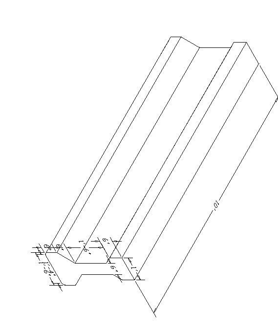
AIM:
To create the 3D view of the AASTHO Type Girder by using Auto CAD
Introduction:
Various commands used:
- QNEW command
- UN command
- Box command
- Rectangle command
- Extrude command
- SUBTRACT command
- DIMLIN command
- 3DO command
- UCS command
Procedure:
step-1: Open Auto CAD software
step-2: Enter the QNEW command to start a new window
step-3: Enter the UN command to set the unit style and fraction value
step-4: Enter the LIMITS command to set the size of the sheet
step-5: Select 3D modeling from the right bottom corner tab
step-6: Type "L" to invoke the line tool and press enter on the screen
step-7: Specify the next point as 1'6" in the direction of X
step-8: Specify the next point as 6" in the direction of y
step-9: Specify the next point as 6" in the direction of negative X
step-10: Specify the next point as 2' in the direction of y
step-11: Specify the next point as 3" in the direction of x
step-12: Specify the next point as 6" in the direction of y
step-13: Specify the next point as 1' in the direction of negative X
step-14: Close the line tool
step-15: Type the MI command in the box to invoke the mirror tool and select the objects we drew
step-16: And mirrored the entire object and we have the girder in 2D
step-17: Type "REG" region the 2D girder
step-18: Type "L" to invoke the line tool and draw a line length up to 10'
step-19: Type "Sweep" in the command box and select the 2D girder region and press enter
step-20: Now select the line and now we have 3D girder.
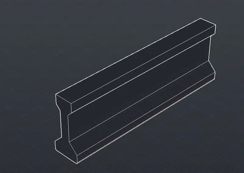
step-21: Type "DIMLIN" to mark all the dimensions in the drawing
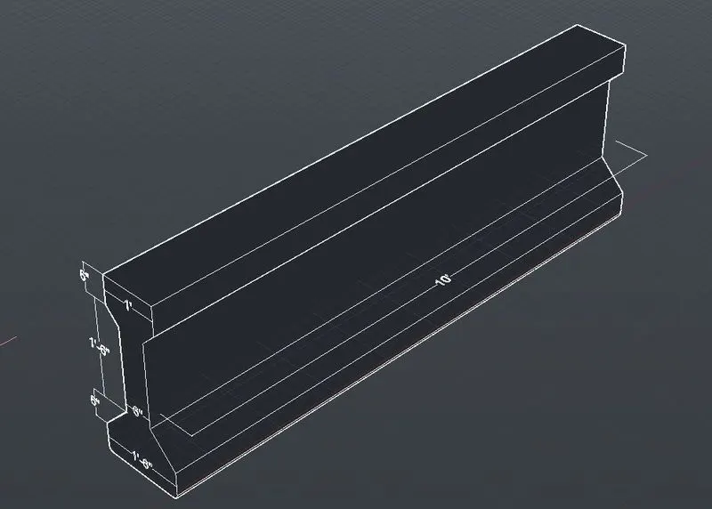
Result:
Finally, we have 3D model of AASHO girder by using Auto CAD 3D software
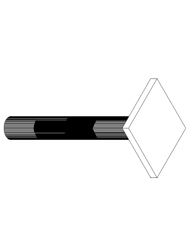
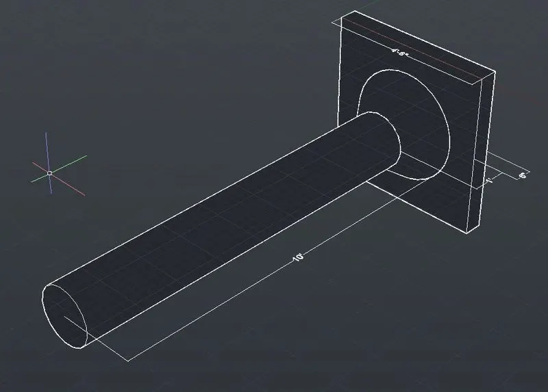
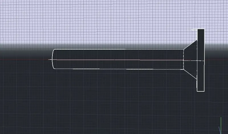
4. Create a 3d Model of a drop column with panel as shown in section and isometric view.
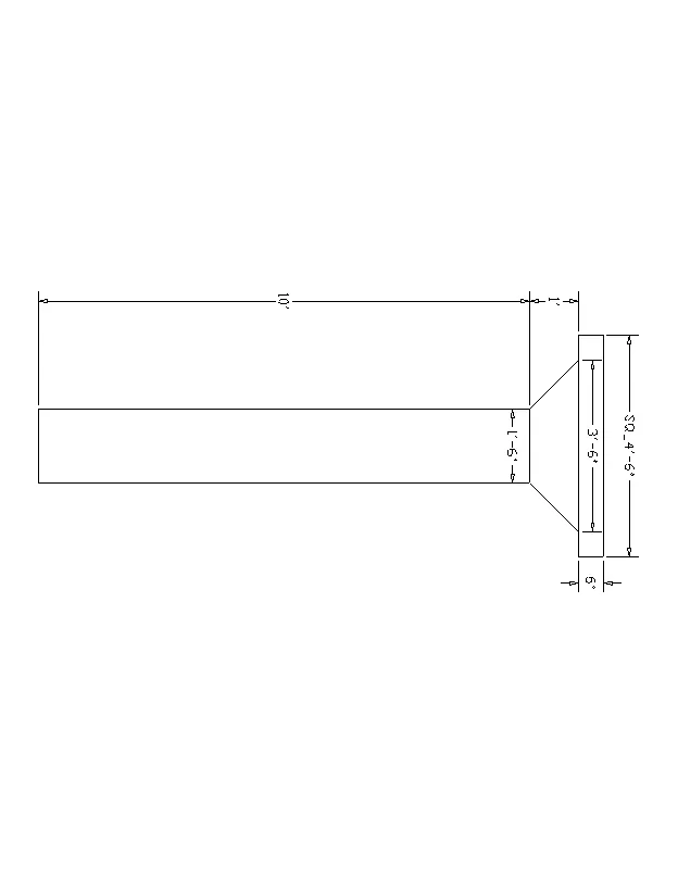
Aim:
To create a 3d Model of a drop column with the panel as shown in section and isometric view by using Auto CAD
Introduction:
Various commands used:
- QNEW command
- UN command
- Box command
- Rectangle command
- Extrude command
- SUBTRACT command
- DIMLIN command
- 3DO command
- UCS command
Procedure:
step-1: Open Auto CAD software
step-2: Enter the QNEW command to start a new window
step-3: Enter the UN command to set the unit style and fraction value
step-4: Enter the LIMITS command to set the size of the sheet
step-5: Select 3D modeling from the right bottom corner tab
step-6: Type "C" circle tool and give radius to draw the circle
step-7: Type "L" to invoke line tool and draw the line
step-8: Type "REG" to region the circle
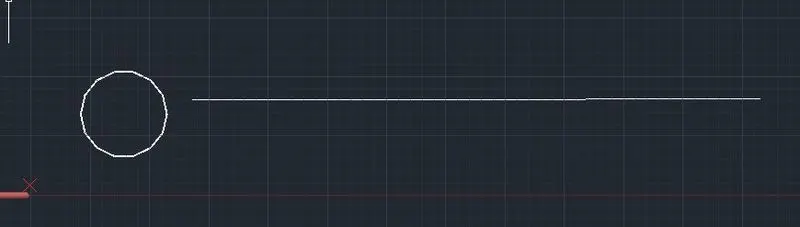
step-9: Type "SWEEP" to sweep the circle to the line
step-10: Type "REC" to draw the rectangle with the dimension of 4'6" on each side
step-11: TYpe "L" to draw the thickness of the rectangle and sweep the rectangle
step-12: Type "C" to draw the circle of 1'6"
step-13: TYpe "L" draw the line
step-14: SWEEP the circle to the line with the scale of 2 times
step-15: Merge three elements into one object
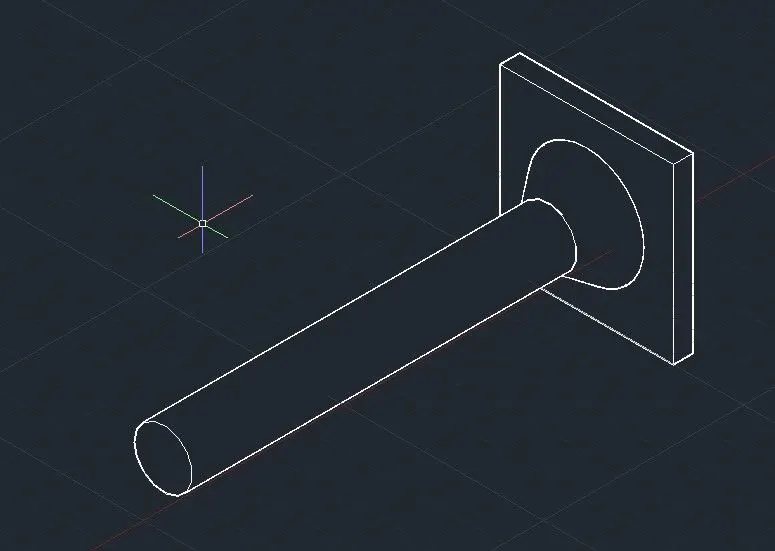
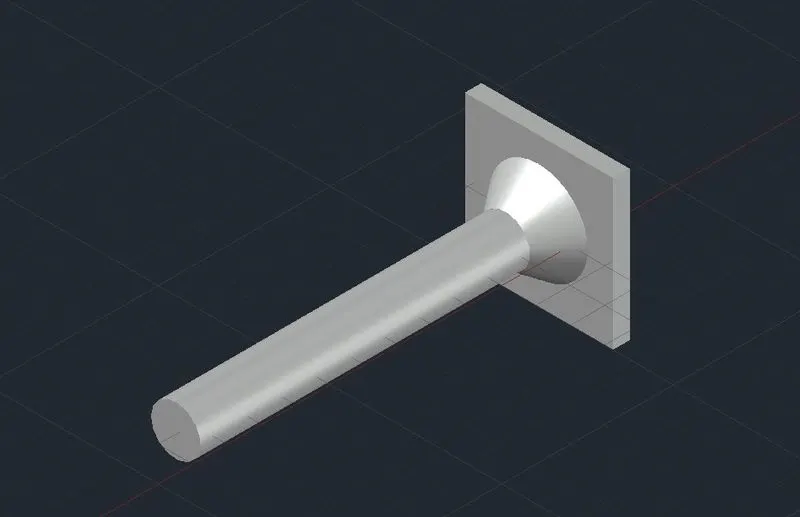
step-16: Type "DIMLIN" to mention all the dimensions in the object
Result:
Finally, we have a 3D model of a drop column with the panel as shown in the section and isometric view by using Auto CAD 3D.
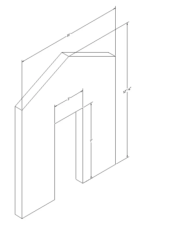
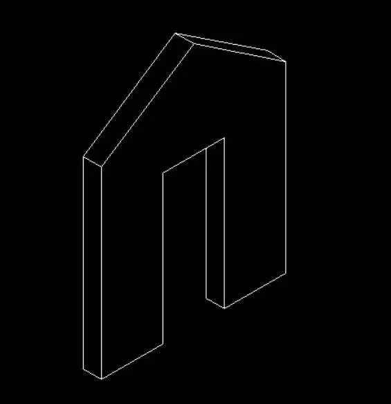
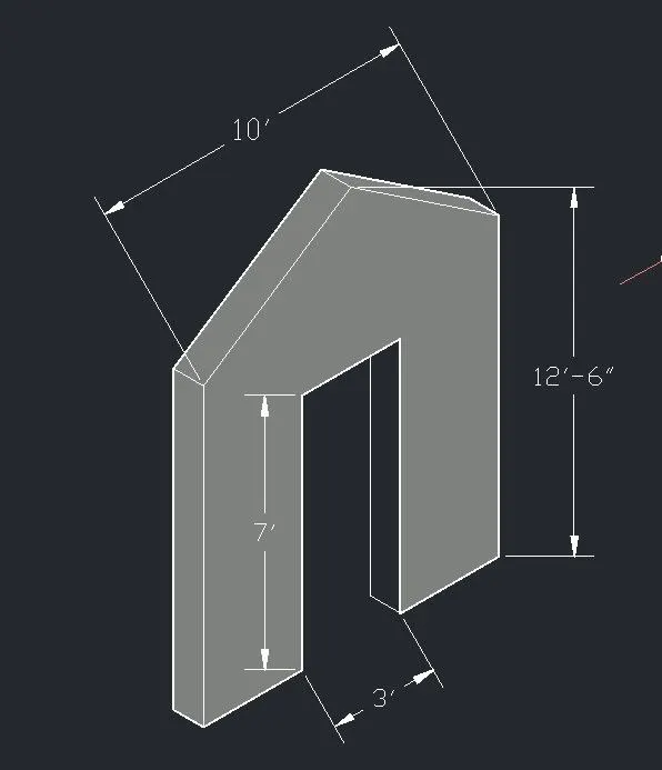
5. Create the 3d model of a wall as shown in Figure. Consider wall thickness as 9”.
Aim:
To create the 3d model of a wall as shown in Figure by using Auto CAD software.
Introduction:
Various commands used:
- QNEW command
- UN command
- Box command
- Rectangle command
- Extrude command
- SUBTRACT command
- DIMLIN command
- 3DO command
- UCS command
Procedure:
step-1: Open Auto CAD software
step-2: Enter the QNEW command to start a new window
step-3: Enter the UN command to set the unit style and fraction value
step-4: Enter the LIMITS command to set the size of the sheet
step-5: Select 3D modeling from the right bottom corner tab
step-6: Type "L" in the command box to invoke the line tool and point anywhere in the sheet to initiate the drawing.
step-7: Type next specify point 3'6"
step-8: Type next specify point 7' in the direction of the +ve z-axis.
step-9: Type next specify point 3' in the direction +ve x-axis
step-10: Type the next specified distance 7' in the direction of the -ve z-axis
step-11: Type next specify point 3'6" in the direction of +ve x-axis

step-12: Type enters to close the tool.
step-13: Type "L" to draw the remaining objects
step-14: Specify the next point 10' in the direction of the Z axis
step-15: close the line tool
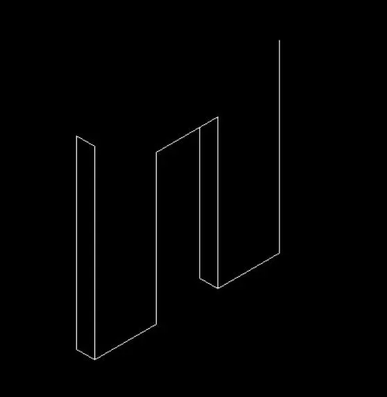
step-16: Re-open the line tool and select another edge of the wall and draw the same
step-17: Mention the wall thickness of 9"
step-18: Type the "REG" region all objects
step-19: Type DIMLIN to mention all the dimensions in the drawing.
Result:
Finally, We created the 3D model of a wall by using Auto CAD software.