Creating various 3D Models like Furniture, Footing, Girder, Column drop with panel and Gable Wall in AutoCad
1.
Aim
To create a 3D Furniture Element as shown in the figure.
Procedure
- Go to AutoCAD and open 3D modelling.
- Then go to top view and in 2D wireframe draw a rectangle
- Offset the rectangle to 2”
- Then use region commend and select the region then press ok.
- Then go to shaded and in 3D use extrude commend and select the region.
- Then extrude to 2’6” in z axis.
- Then use union commend to join the solids.
- Use dimension commend to give dimension at required places.
Output
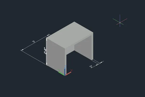
Result
Thu the 3D of furniture element has been created using AutoCAD 3D
2.
Aim
To create the 3D model of Isometric footing as shown in the figure.
Procedure
- Go to AutoCAD and open 3D modelling.
- In 3D view use Box commend then draw a rectangular box of 5’ x5’ x6”.
- Then create another box on the top of the created box at a height of 2’
- Then go to front view and draw a line of 1’ and select the mid-point and place it in the midpoint of box.
- Then use slice commend and select the object and select then click on the bottom corner and then click on the start of line.
- Then use erase comment to erase the extra box.
- Similarly repeat the same procedure for opposite sides.
- Then use region commend and create region. Then give dimension where ever required.
Output
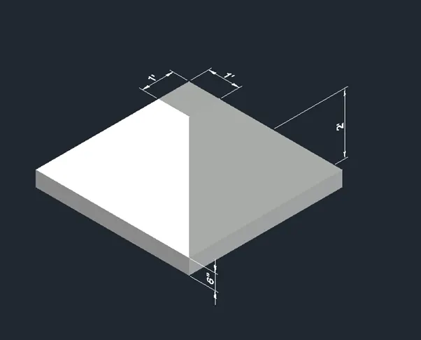
Result
Thus the 3D model of Isometric footing has been created.
3.
Aim
To create the 3D view if AASTHO type Girder.
Procedure
- Go to AutoCAD and open 3D modelling.
- Go to top view and in 2D wireframe.
- Use line commend to draw give girder.
- Use chamfer commend and other necessary commends.
- Then go to 3D and create region by using region commend.
- Then use extrude commend and select the region then extrude to height of 10’
Output
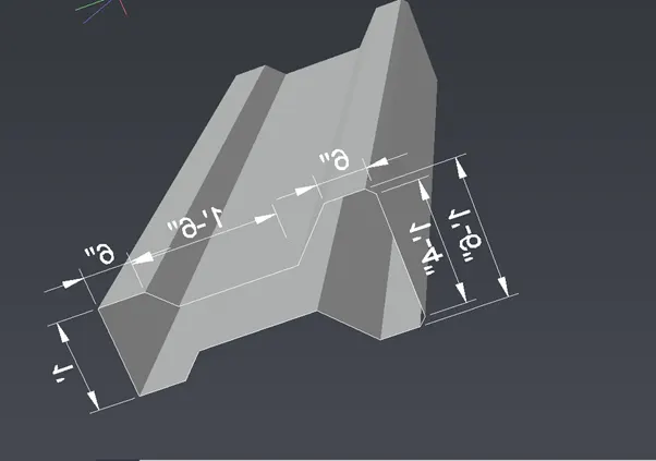
Result
Thus the 3D view of Girder has been created.
4.
Aim
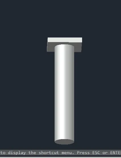
To create a 3D model of a drop column with panel as shown in the figure.
Procedure
- Go to AutoCAD and open 3D modelling.
- In 3D view use Box commend then draw a rectangular box of 4’6” x4’6” x6”.
- Then create another box on the top of the created box at 3’6” x 3’6” x 1’6”
- Then go to front view and draw a line of 1’6” and select the mid-point and place it in the midpoint of box.
- Then use slice commend and select the object and select then click on the bottom corner and then click on the start of line.
- Then use erase comment to erase the extra box.
- Similarly repeat the same procedure for opposite sides.
- Then use region commend and create region.
- Then use extrude commend and select the region then extrude to height of 10’
- Then give dimension where ever required.
- Repeat the same procedure for creating the figure shown.
Output
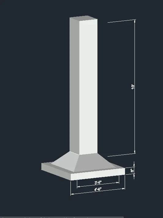
Result
Thus the 3D model of drop column has been created
5.
Aim
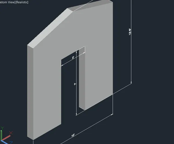
To create a 3D model of wall panel as shown in the figure.
Procedure
- Go to AutoCAD and open 3D modelling.
- Go to top view and in 2D wireframe.
- Use line commend to draw give wall panel.
- Then go to 3D and create region by using region commend.
- Then use extrude commend and select the region then extrude to height of 10’
- Then use subtract commend to remove the door area.
- Then create a triangle at the top of the wall and create region and the extrude to 9”.
- Thus the wall has been created.
Output
Result
Thus the 3D wall has been created.