Creating various 3D Models like Furniture, Footing, Girder, Column drop with panel and Gable Wall in AutoCad
1. Create a 3D Furniture element as shown in the Figure. Assume dimensions which are missing.
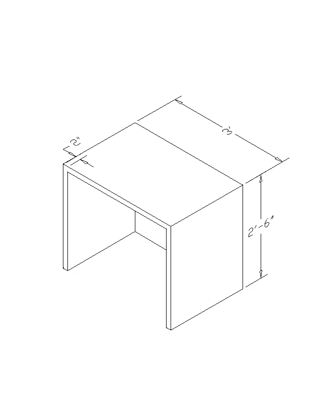
Aim:
To create a 3D Furniture element as shown in the Figure using the AutoCAD software
Introduction:
Create a 3D Furniture element as shown in the Figure. Assume dimensions which are missing.
Procedure:
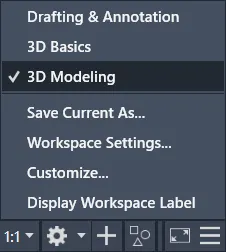
- First open the 3D modeling in the AutoCAD worspace
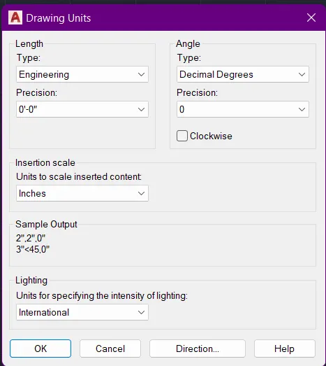
- Then set the units of the drawing is, type UN for units command
- And give the type of the length is Engineering, precision is 0'-0"
- the Insertion scale is Inches finally click OK button
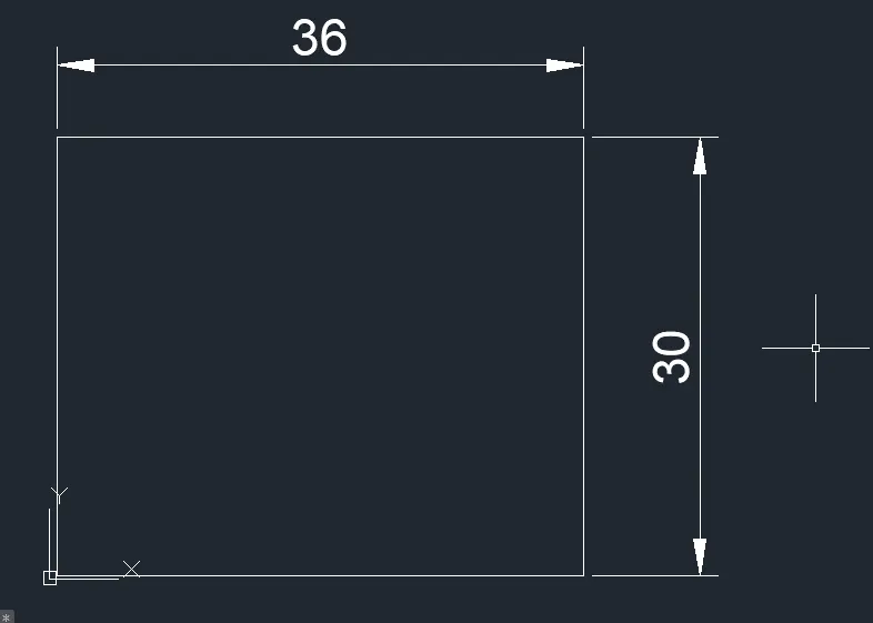
- Then draw the rectangle using REC command as given in the question
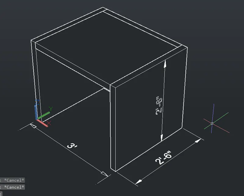
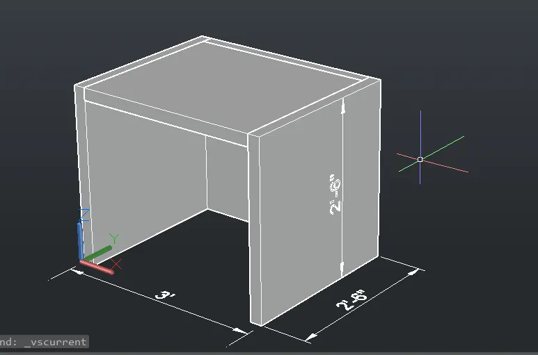
- The size of the rectangle is 3' x 2' 6"
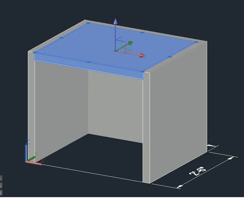
- Using the 3D navigation cube to change the screen the 3D and the draw the vertical covering object of the rectangle

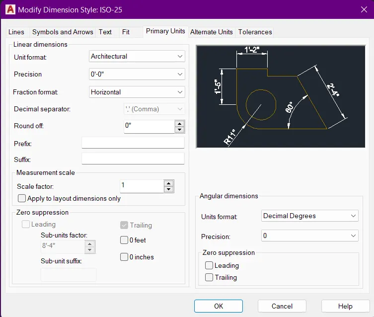
- Here, chenging the Primary units to the Architectural and the precision is 0'-0" by using the Dimstyle command
- Click OK - Setcurrent and Close button
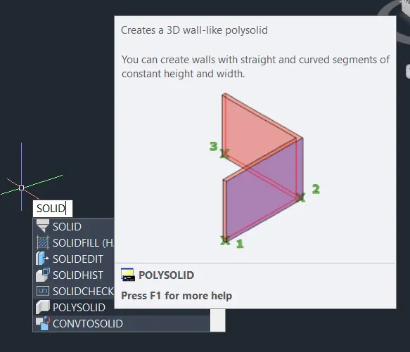
- After create the vertical line of the rectangle box by using the Polysolid to create a solid element in the furniture element
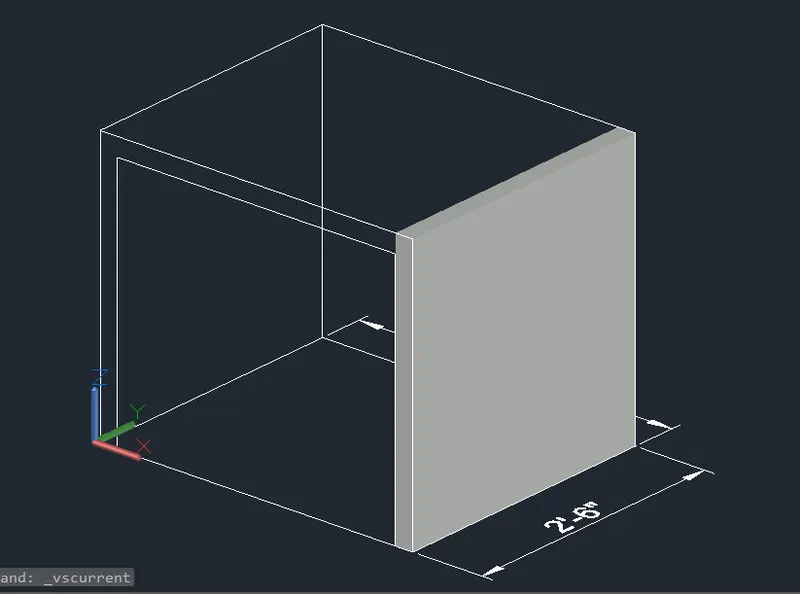
- And the command of Extrusion to the balance object to create the vertical and horizontal components
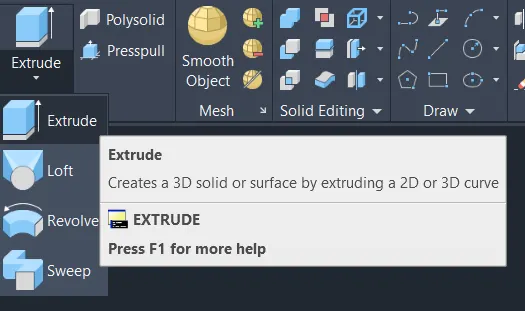
- Click the Extrude and create the element
- Finally create the furniture element as below shows figures
- At last take the screenshots using the command of Windows key+Shift+S
- And upload the drawings to the given question
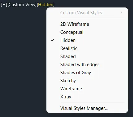
- Click the Custom visual style in the work space and click the Hidden to take the 2D hidden lines. It shows Isometric view of the drawing
Result:
The creation of a 3D Furniture element as shown in the Figure using the AutoCAD software is drawn successfully
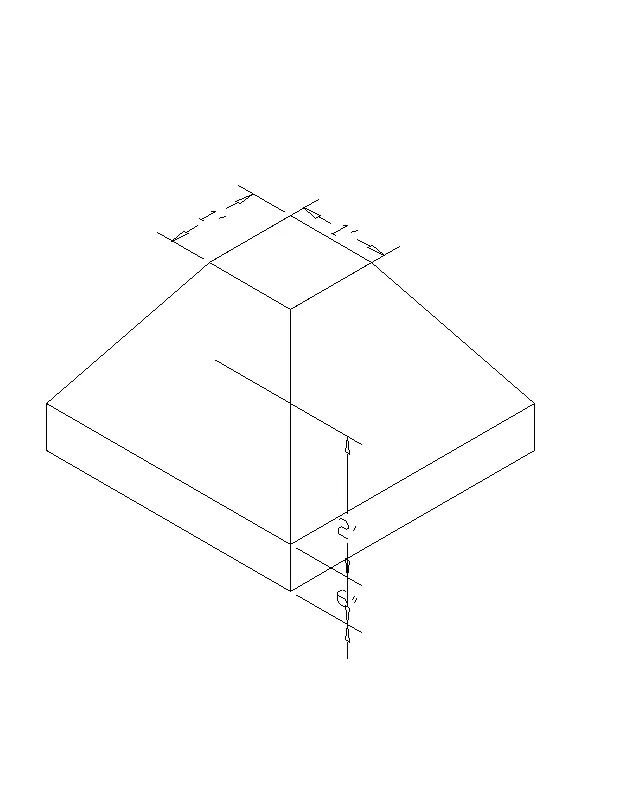
2. Create the 3d Model of an Isolated footing as shown in Figure.
Aim:
To create the 3d Model of an Isolated footing as shown in Figure using the AutoCAD software
Introduction:
Create the 3d Model of an Isolated footing as shown in Figure
Procedure:
- First open the 3D modeling in the AutoCAD worspace
- Then set the units of the drawing is, type UN for units command
- And give the type of the length is Engineering, precision is 0'-0"
- the Insertion scale is Inches finally click OK button
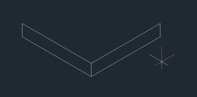
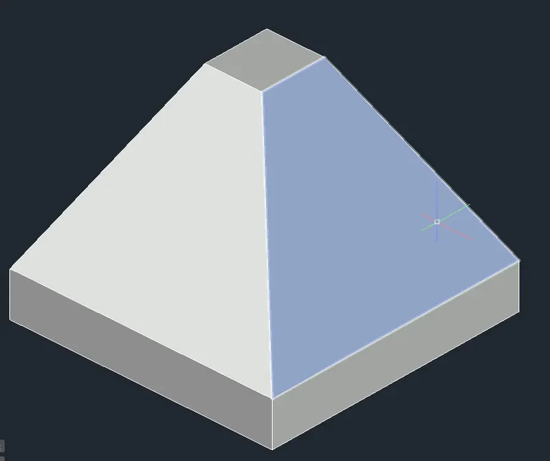
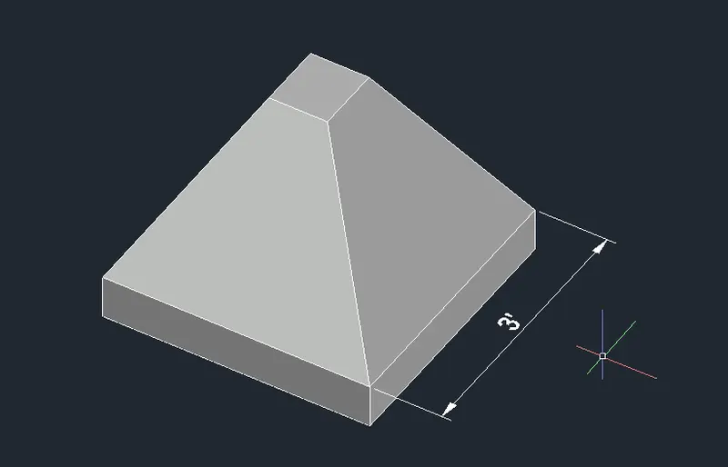
- Create the line drawing of the footing bottom portion by using the Line command in isometric view
- Then create the inner square of the footing is drawn using the REC command for rectangle
- And using the 3DMove command for the square drawing upward direction in the Height of 2'
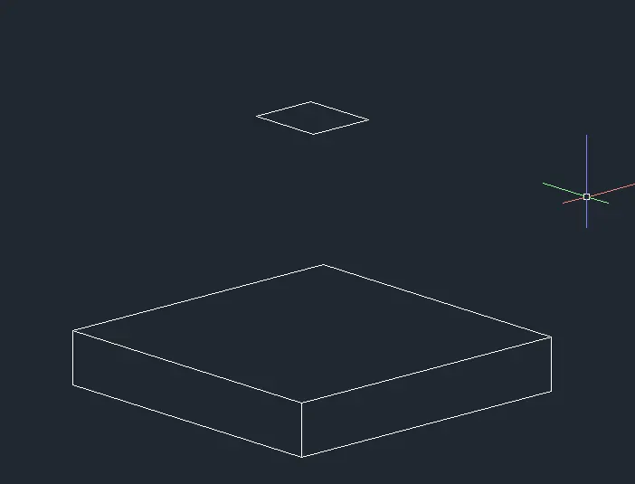
- Here using the 3DFace command for creating the all inclined face of the footing
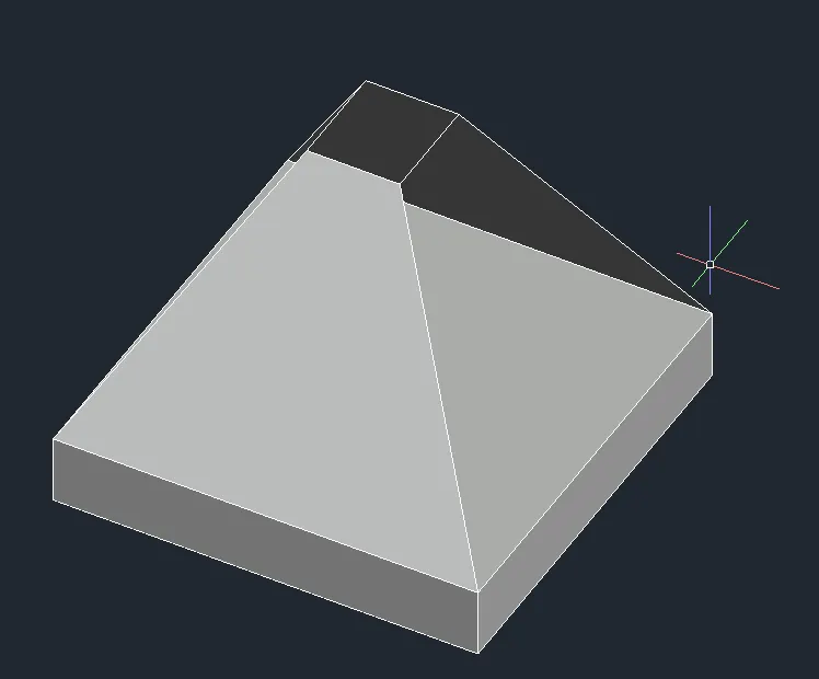
- Finally create the 3DFaces in the tappered sections and Take the screenshots
- At last take the screenshots using the command of Windows key+Shift+S
- And upload the drawings to the given question
Result:
The creation of 3D isolated footing as shown in figure is created using theAutoCAD software is successfully
3. Create the 3D view of the AASTHO Type Girder.
Aim:
To create the 3D view of the AASTHO Type Girder by using the AutoCAD software
Introduction:
Create the 3D view of the AASTHO Type Girder
Procedure:
- First open the 3D modeling in the AutoCAD worspace
- Then set the units of the drawing is, type UN for units command
- And give the type of the length is Engineering, precision is 0'-0"
- the Insertion scale is Inches finally click OK button
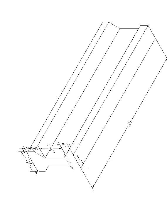
- The AASTHO type girder is created by using the Line command for draw the section of the girder as per given in dimension
- And then draw the line of 10' with connect the drawing of girder drawing
- Then using the Sweep command for create through the 10' line
- Select the object and click the line and then click Enter button
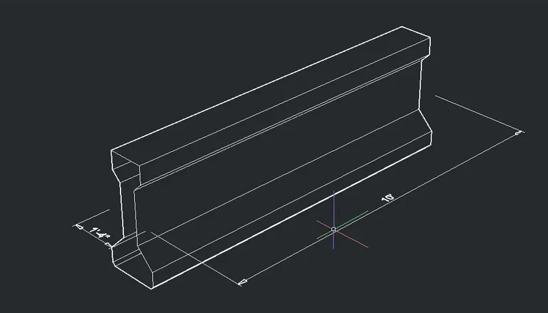
- Using the Custom visual style menu to change the drawing on Realistic option to make the drawing to real look of the girder
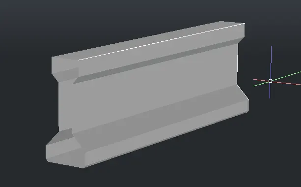
- Finally create the AASTHO girder as below shows figures
- At last take the screenshots using the command of Windows key+Shift+S
- And upload the drawings to the given question
Result:
The creation of 3D drawing of AASTHO girder is created by using the AutoCAD software is successfully
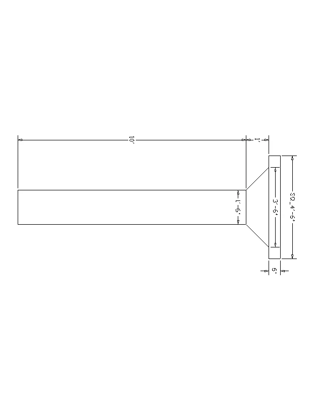
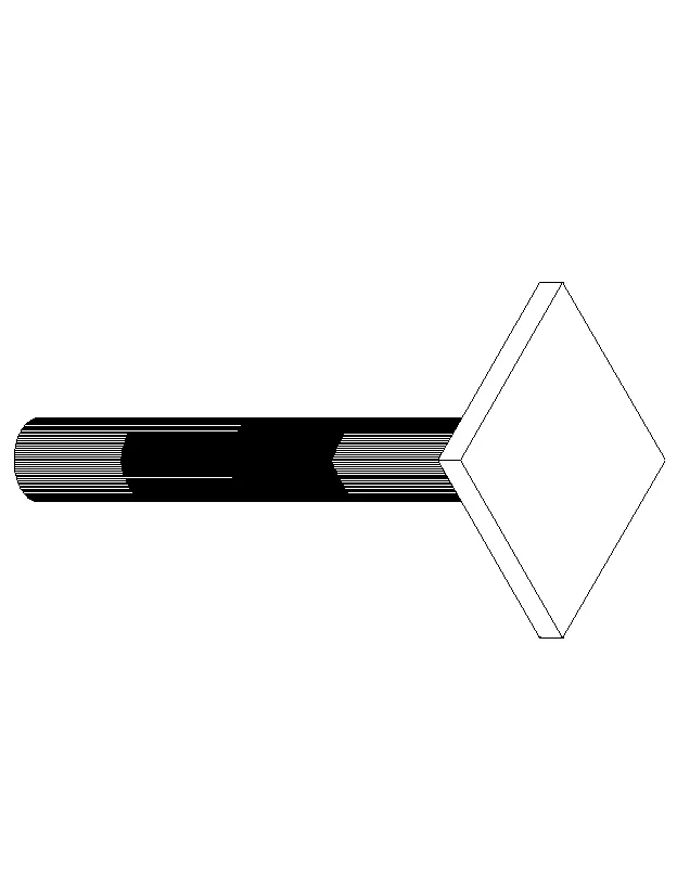
4. Create a 3d Model of a drop column with panel as shown in section and isometric view.
Aim:
To create a 3d Model of a drop column with panel as shown in section and isometric view using the AutoCAD software
Introducton:
Create a 3d Model of a drop column with panel as shown in section and isometric view
Procedure:
- First open the 3D modeling in the AutoCAD worspace
- Then set the units of the drawing is, type UN for units command
- And give the type of the length is Engineering, precision is 0'-0"
- the Insertion scale is Inches finally click OK button
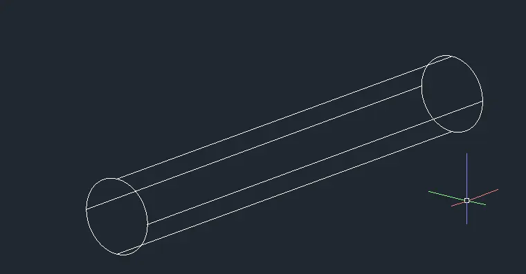
- Using the Circle command and draw the circle the dia of 1'6"
- Then draw the line the length of the line is 10'
- Using the Sweep command and assign the circle to the line
- Create the 2D drawing of the drop panel column using the Line command as given in the question
- And using the Dimlinear command for take the dimension of the drawing
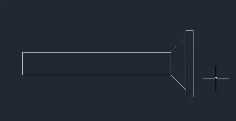
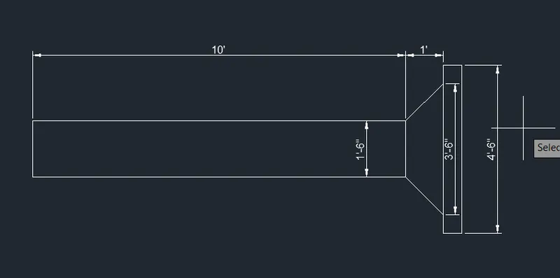
- Attach the drawing of circle column with the 2D drawing of drop panel column
- And create the faces by using the 3DFace command and create the all side faces
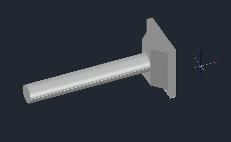
- Using the Custom visual style menu to change the drawing on Realistic option to make the drawing to real look of the girder
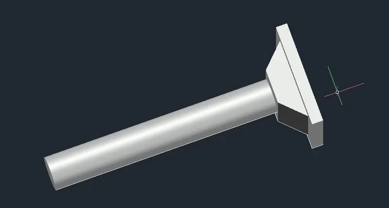
- Finally create the Drop panel with circular column as below shows figures
- At last take the screenshots using the command of Windows key+Shift+S
- And upload the drawings to the given question
Result:
The creation of 3d Model of a drop column with panel as shown in section and isometric view is completed by using the AutoCAD software is successfully
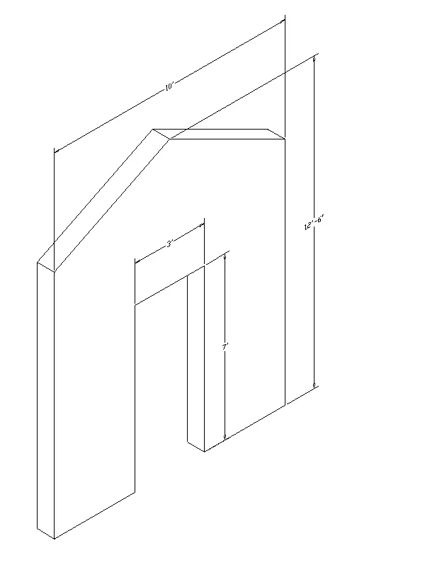
5. Create the 3d model of a wall as shown in Figure. Consider wall thickness as 9”.
Aim:
To create the 3d model of a wall as shown in Figure using the AutoCAD software
Introduction:
Create the 3d model of a wall as shown in Figure. Consider wall thickness as 9”
Procedure:
- First open the 3D modeling in the AutoCAD worspace
- Then set the units of the drawing is, type UN for units command
- And give the type of the length is Engineering, precision is 0'-0"
- the Insertion scale is Inches finally click OK button
- Here, draw the wall drawing by using the isometric lines in 3D workspace
- This drawing is drawn by as per given in the question drawing
- And the wall thickness is 9" is used
- Then using the DImlinear command to take the dimension of the drawing
- The slope of the wall is created by assumption of the height is 2'6" from the straight vertical line
- And using the 3DFace command for create the wall in realistic
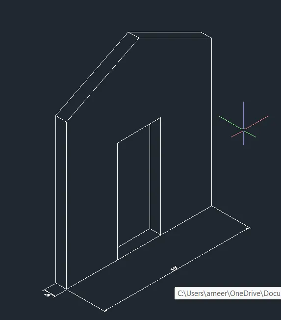
- Using the Custom visual style menu to change the drawing on Realistic option to make the drawing to real look of the girder
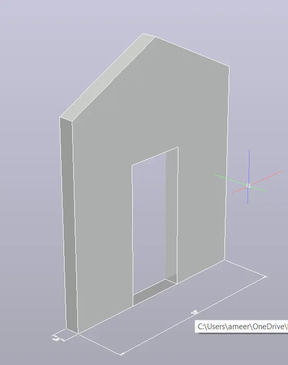
- Finally create the model wall as below shows figures
- At last take the screenshots using the command of Windows key+Shift+S
- And upload the drawings to the given question
Result:
The creation of 3D of a wall as shown in Figure is created using the AutoCAD software is successfully