Creating various 3D Models like Furniture, Footing, Girder, Column drop with panel and Gable Wall in AutoCad
1.AIM
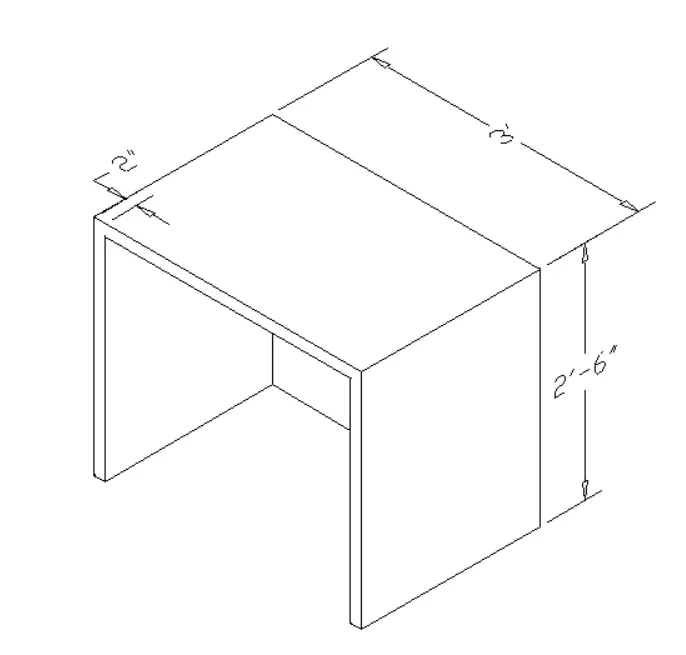
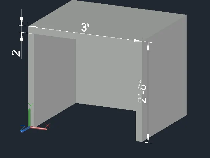
To Create a 3D Furniture element as shown in the Figure
COMMANDS USED
- Line
- Extrude
- Offset
- 3dorbit
- Region
- Boundary
- trim
- dimlinear
- rectangle
- ucs
INTRODUCTION
In 3D modelling, we use the design we have created using 3D drawing commands and then makes things out of it .Different types of 3D models are there and they are
- Wireframe models
- Surface models
- Soilid models
PROCEDURE
STEP1
- Open a new file
- Go to settings and change view of the page from drafting to 3D modelling
- In the command line type units , select the unit and also set the precision
- In the command line type 'LIMITS' and specify the limits at lower left corner and upper right corner as
- Then zoom all
STEP2
- By taking top view of the page
- Using rectangular command draw rectangle of length 3' and width 2'-6"
- using dimlinear mark the dimensions
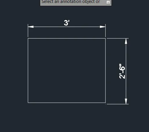
- Using the region command and select the object
- Change from 2D wireframe to shaded
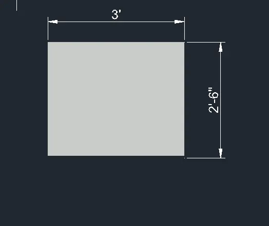
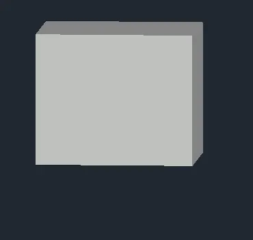
- Using the extrude command extrude the rectangle to a height of 2'-6"
- Using 3D orbit command orbit the object
STEP3
- Select the front face
- Then by using the ucs command , select face and click on face and select the front face
- Using the PLAN command front face is alligned properly
- using the line command draw line og 2" from the sides and top and trim the unwanted lines
- Using the rectangular command draw a rectangle inside the drawn 2" lines
- Then delete the 2" lines from the sides and top
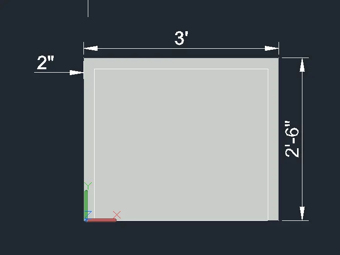
- Using the "3do" command orbit the object and then select the rectangle
- Using the extrude command extrude the rectangle to -Zaxsis 2'-4"
- Using the subtract command ,subtract the extruded rectangle for that select the larger rectangle then the smaller extruded rectangle in 2d wireframe model
- Dimensions are marked using dimlinear command
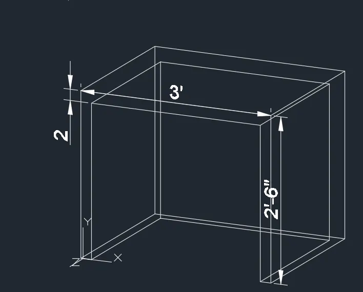
RESULT
3D model of furniture element is created
---------------------------------------------------------------------------------------------------------------------------------------------
2.AIM
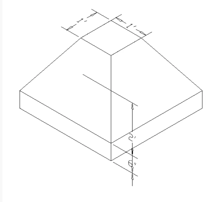
To Create the 3d Model of an Isolated footing as shown in Figure.
COMMANDS USED
- Line
- Extrude
- Offset
- 3dorbit
- Region
- Boundary
- trim
- dimlinear
- rectangle
- ucs
INTRODUCTION
In 3D modelling, we use the design we have created using 3D drawing commands and then makes things out of it .Different types of 3D models are there and they are
- Wireframe models
- Surface models
- Soilid models
PROCEDURE
STEP1
- Open a new file
- Go to settings and change view of the page from drafting to 3D modelling
- In the command line type units , select the unit and also set the precision
- In the command line type 'LIMITS' and specify the limits at lower left corner and upper right corner as
- Then zoom all
STEP2
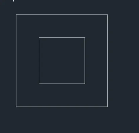
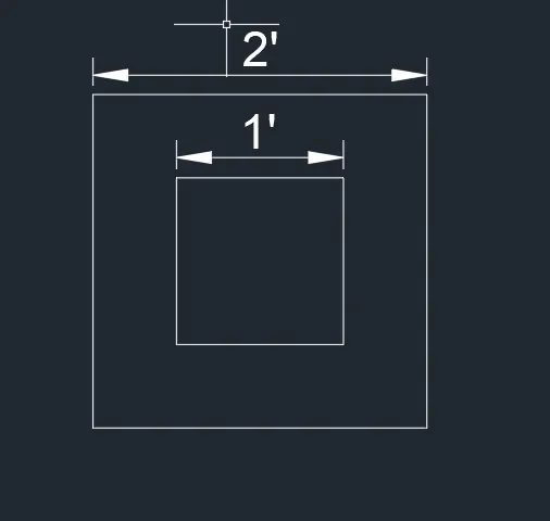
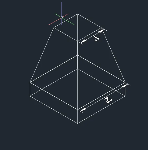
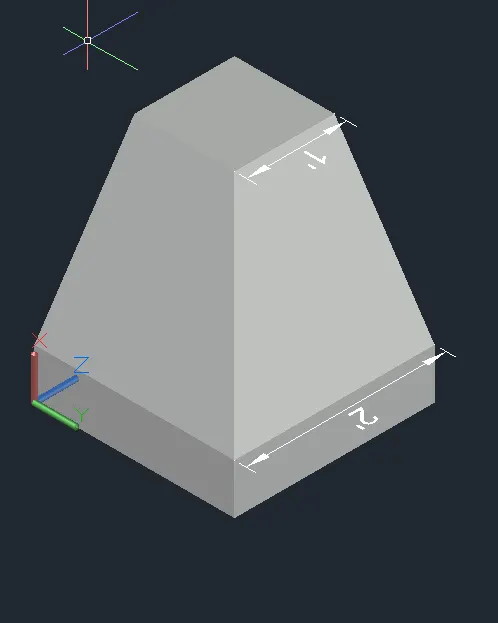
- Using the rectangular command draw rectangle of 2'*2' on top of that draw other rectangle of 1'*1'on the top view
- Using dimlinear mark the dimensions
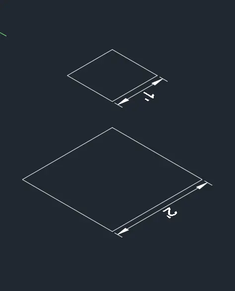
- Using "3do" command orbit the view to a suitable one
- Using the move command move the smaller rectangle by 2' in +z direction with the ortho mode on
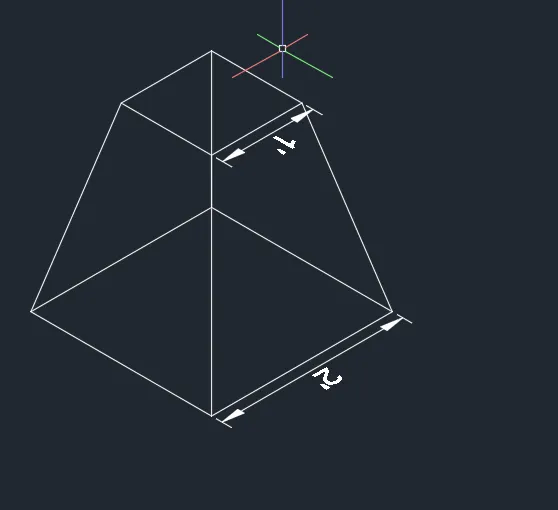
- using the loft command select the two rectangles for lofting
- Then go to the top view and draw a rectangle above the larger rectangle drawn
- Using "3do" command orbit the view to a suitable on
- Using the extrude command select the rectangle drawn and extrude it to a distance of 6" direction we can point by using mouse
RESULT
3D model of isolated footing is created
---------------------------------------------------------------------------------------------------------------------------------------------
3.AIM
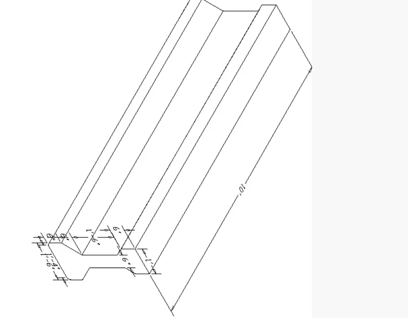
To Create the 3D view of the AASTHO Type Girder.
COMMANDS USED
- Line
- Extrude
- Offset
- 3dorbit
- Region
- Boundary
- trim
- dimlinear
- rectangle
- ucs
INTRODUCTION
In 3D modelling, we use the design we have created using 3D drawing commands and then makes things out of it .Different types of 3D models are there and they are
- Wireframe models
- Surface models
- Soilid models
PROCEDURE
STEP1
- Open a new file
- Go to settings and change view of the page from drafting to 3D modelling
- In the command line type units , select the unit and also set the precision
- In the command line type 'LIMITS' and specify the limits at lower left corner and upper right corner as
- Then zoom all
STEP2
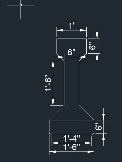
- Using the line command draw a line of 1' continue it and draw 6" line vertically downward direction
- using offset command offset 6" line to the other side
- Then by using line command from the center of line 1' draw a line of 9" and offset that line to both side with 3"
- So that the width of the web becomes 6"
- Then we need to give a taper distance and can join the web and the flange
- Mirror the same to the other side
- Web is given a height of 1'-6" and offset it
- delete the center line
- Using trim command trim all the unwanted lines
- Extend the web to the offseted line
- then again offset 6" from the last line and taper the sides
- Mirror the tapered portion to the other side
- tapering shoulde be done in such a manner that the bottom should be 1'-6"
- then again line command draw center line
- Using the offset command offset it to both sides by 9"
- then join the taper
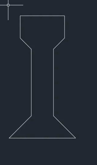
- Using line command draw a vertical line of 6" from 1'-6" line and offset it to the other side also
- draw a center line from the 1'-6" line and offset 8" to both the sides and connect the line
- and trim off the unwanted lines
- Using dimlinear command mark the dimensions
STEP3
- Using the region command convert the whole drawing to 1 region

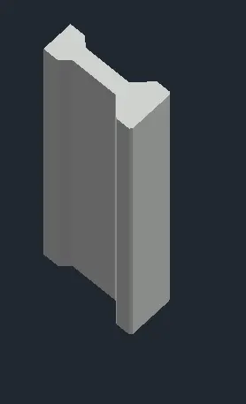
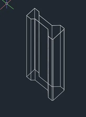
- using extrude command extrude to a distance of 10'
RESULT
3D view of the AASTHO Type Girder is created
--------------------------------------------------------------------------------------------------------------------------------------------
4.AIM
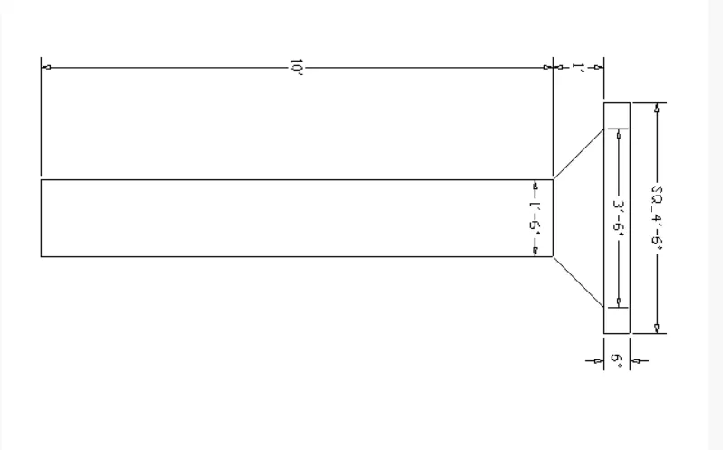
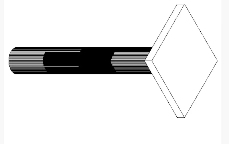
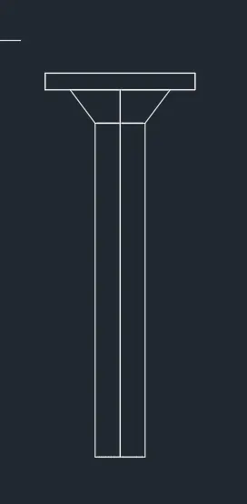
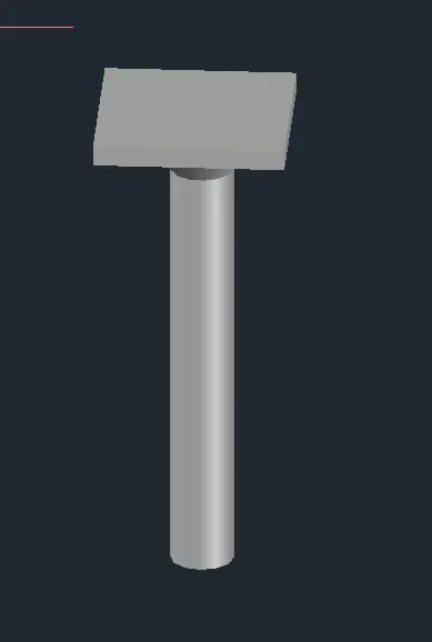
To Create a 3d Model of a drop column with panel as shown in section and isometric view.
COMMANDS USED
- Line
- Extrude
- Offset
- 3dorbit
- Region
- Boundary
- trim
- dimlinear
- rectangle
INTRODUCTION
In 3D modelling, we use the design we have created using 3D drawing commands and then makes things out of it .Different types of 3D models are there and they are
- Wireframe models
- Surface models
- Soilid models
PROCEDURE
STEP1
- Open a new file
- Go to settings and change view of the page from drafting to 3D modelling
- In the command line type units , select the unit and also set the precision
- In the command line type 'LIMITS' and specify the limits at lower left corner and upper right corner as
- Then zoom all
STEP2
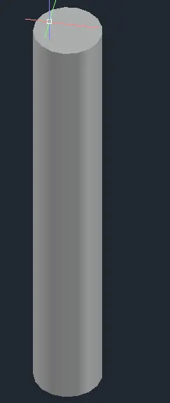
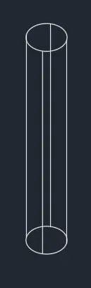
- Using the circle command draw circle of size 1'-6"
- use region command
- Using extrude command extrude it to a distance of 10'

STEP3
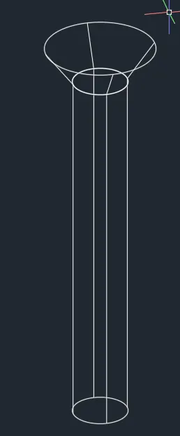
- Using cone command draw a cone of diameter 1'-6" and then select top radius as 1'-6"
- And give height as 1'
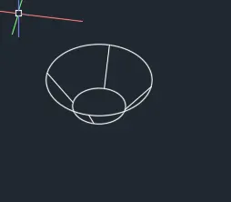
- Now can place the frustum of cone above the extruded circle
STEP4
- Using rectangular command draw rectangle of size 4'-6"*4'-6"
- Using extrude command extrude it to a height of 6"
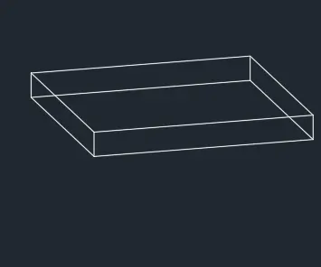
- Now place the extruded rectangle should be placed above the cone which is placed above the extruded circle
RESULT
3d Model of a drop column with panel is created
---------------------------------------------------------------------------------------------------------------------------------------------
5.AIM
To Create the 3d model of a wall
COMMANDS USED
- Line
- Extrude
- Offset
- 3dorbit
- Region
- Boundary
- trim
- dimlinear
- rectangle
- ucs
INTRODUCTION
In 3D modelling, we use the design we have created using 3D drawing commands and then makes things out of it .Different types of 3D models are there and they are
- Wireframe models
- Surface models
- Soilid models
PROCEDURE
STEP1
- Open a new file
- Go to settings and change view of the page from drafting to 3D modelling
- In the command line type units , select the unit and also set the precision
- In the command line type 'LIMITS' and specify the limits at lower left corner and upper right corner as
- Then zoom all
STEP2
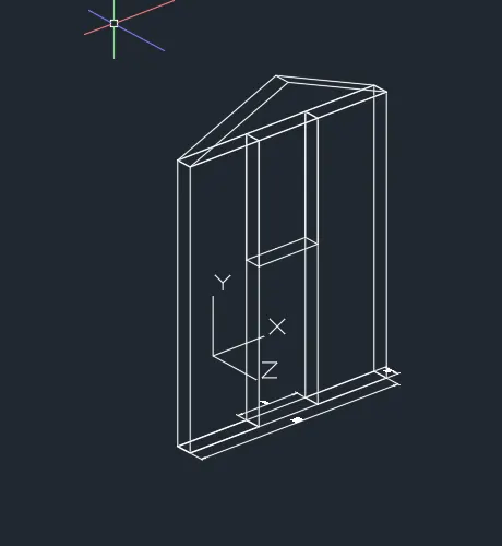
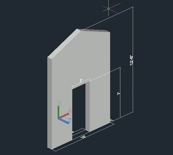
- Using the rectangle command draw a rectangle of 10'*9"
- Using line command draw a line at the center and offset it by 1.5' to both sides for making the door openings
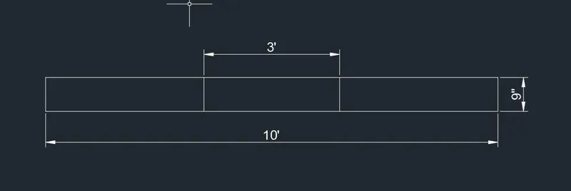
- Using "BO" command boundary is created on the either side of the door opening
- using the extrude command extrude the regions with the height of 12'-6"
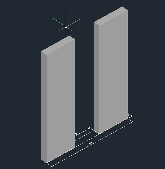
- In the door space draw a rectangle and and move it to height of 7' in z axsis and then extrude it
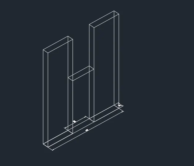
- Go to the front view and draw a line from the center of the moved line of door
- Draw slanting line from the total height from the center line intersecting the edge
- using mirror command mirror it to the other side
- Trim off the excess lines
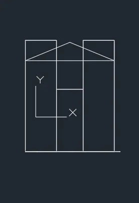
- Using the join command join the traingle
- Create the region with the created triangle
- Extrude the traingle to backside
- extrude the rectangle moved up for the door until the base of the triangle
- then union all the boundaries
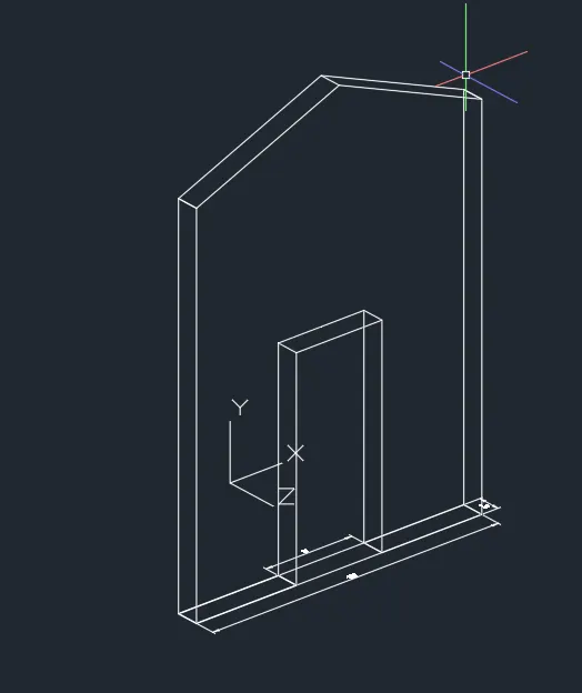
- Dimensions are marked using dimlinear and ucs
RESULT
3d model of a wall is created
---------------------------------------------------------------------------------------------------------------------------------------------