Creating various 3D Models like Furniture, Footing, Girder, Column drop with panel and Gable Wall in AutoCad
- Create a 3D Furniture element as shown in the Figure. Assume dimensions which are missing.
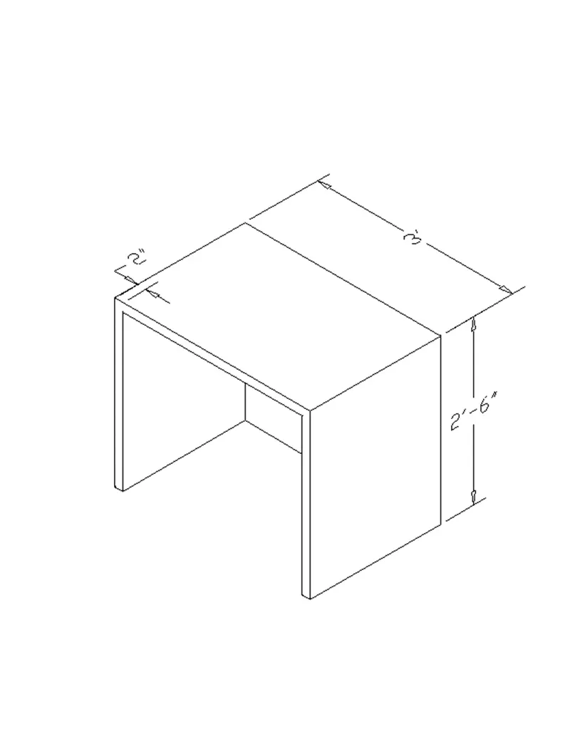
AIM: To create a 3D Furniture element as given in the figure and need to assume dimensions which are missing in the drawing.
INTRODUCTION: -
- 3D CAD, or three-dimensional computer-aided design, is technology for design and technical documentation, which replaces manual drafting with an automated process.
COMMANDS USED: -
- Line command
- Rectangle command
- UCS command
- Dim linear command
- Region command
- Extrude command
- Subtract command
- Box command
- Units command
- Dim style command
- 3Dface command
- 3Dorbit command
- Hide command
- Explode command
- Move command
- Copy command
- Dist. command
Procedure:
- Open AutoCAD, select imperial as the units are in feet and inches. Go to units’ command and set it to engineering, so that feet inches can be inserted.
- Create a box by clicking from the toolbar or box command, click on length, give the length as 3' and width as 2'6". Height is to be specified, give the height as 2'6".
- Select the front face, command "UCS" give the x and y coordinate in the front face horizontally and vertically respectively or click on face and select the front face. Type the command "PLAN" so that the front face is aligned correctly.
- Draw a line of 2" from the right side of the front view. By rectangle command, draw a rectangle of dimension 32" and 2'4" (as the thickness is given as 2")
- Move the rectangle to the line drawn earlier 2" from the right of the face.
- Delete the line created earlier. Now with command "3do" orbit the object and select the rectangle.
- Extrude the rectangle to -z axis 2'4" leaving 2" thickness. Now give the command "Subtract" select the larger object then the smaller extruded rectangle in 2d wireframe model.
- Dimensions are given by dim linear command by switching the UCS.
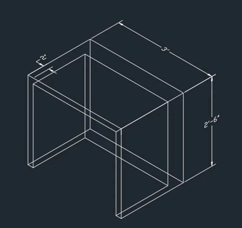
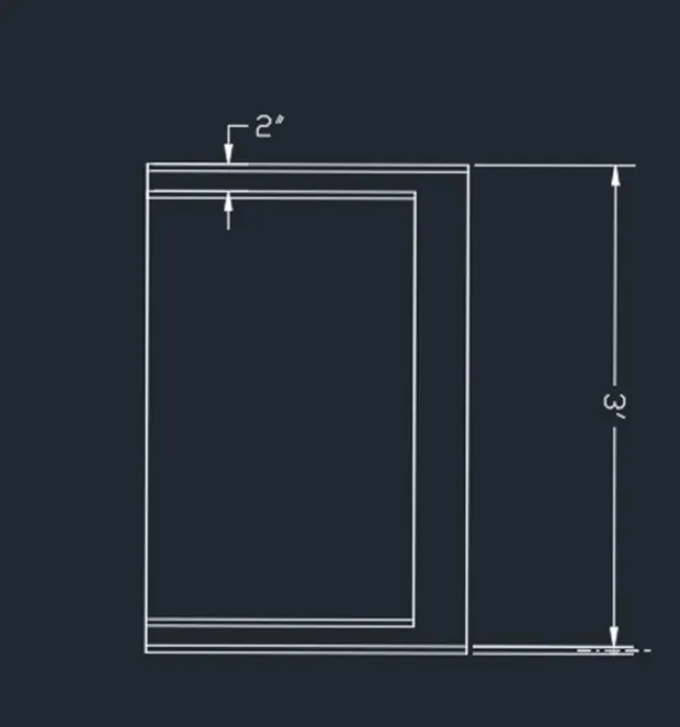
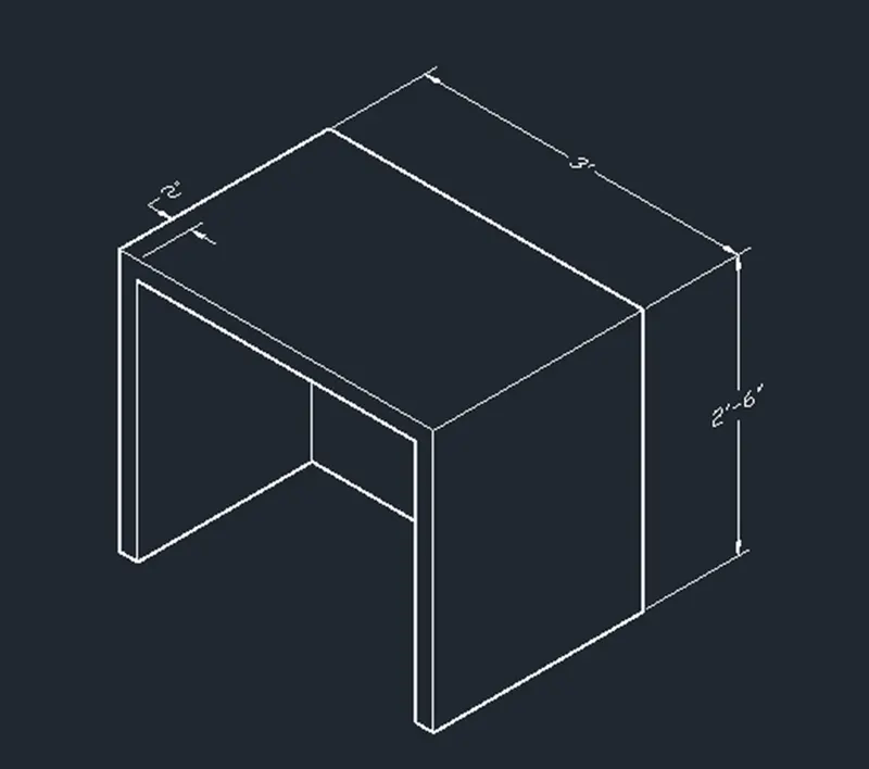
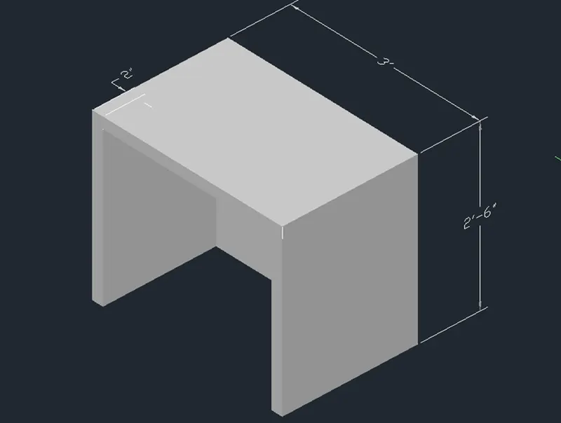
Result: The 3D model of furniture element is created.
- Create the 3d Model of an Isolated footing as shown in Figure.
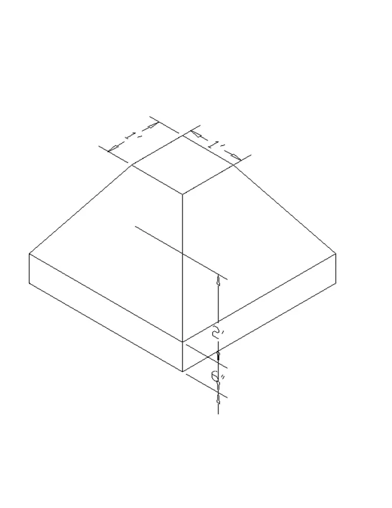
AIM: To create a 3D model of an isolated footing in the AutoCAD in detail.
INTRODUCTION: -
- The three dimensional of isolated footing was drawn in the AutoCAD using the different tools in the AutoCAD.
- 3D models are widely used anywhere in 3D graphics and CAD.
- Their use predates the widespread use of 3D graphics on personal computers.
- The 3d models are mainly preferable in civil engineering and when we design a building in the AutoCAD then creating 3d models should be a must.
COMMANDS USED: -
- Line command
- Rectangle command
- UCS command
- Dimlinear command
- Region command
- Extrude command
- Substract command
- Box command
- Units command
- Dimstyle command
- 3Dface command
- 3Dorbit command
- Hide command
- Explode command
- Move command
- Copy command
- Dist command
- Rulesurf command
PROCEDURE: -
- First, we have to open the AutoCAD and set the units using the units' command.
- Next select the dimstyle command and select primary units as architectural.
- Next, we use the UCS command to set the directions of x-axis, y-axis and z-axis.
- Next, we draw the rectangle using the line command with the size of 3' x 3'.
- Next, we use extrude command to extrude the rectangle upwards with the length of 6".
- Next again we draw another rectangle at the center of the outer rectangle.
- Next, we use the move command to move the inner rectangle upwards with the length of 2'.
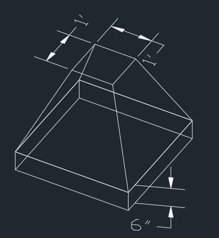
- Next, we use the Rule surf command to join the 4 corners of the moved rectangle and four corners of extruded rectangle to co-ordinate each other.
- Next, we need to use 3Dface command to visible as a 3d model as shown in the figure.
- Next, we use the hide command and press enter, then we select the four corners of every part in the drawing.
- After selecting the four corners of every part in the drawing and then press enter, the lines visible in the part will hide automatically after pressing the enter.
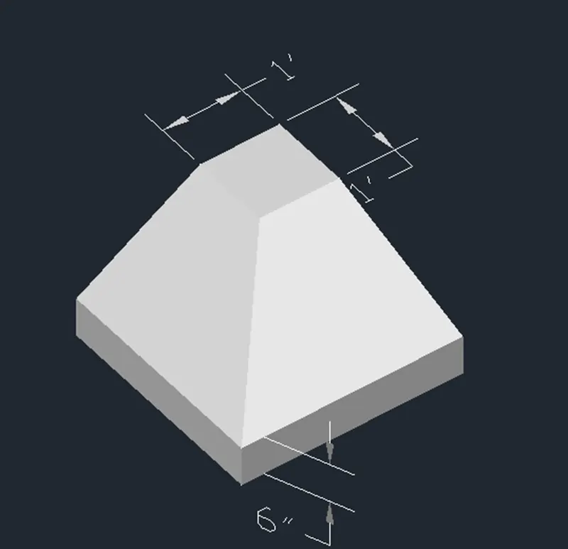
- Next, we need to put the dimensions for every part in the drawing as shown in the below figure
- Next, we click the custom visual styles at the top left corner of the drawing screen, and select the shaded option in the custom visual styles.
RESULT: -
- The given 3D model of the isolated footing is drawn successfully in the AutoCAD in detail.
3. Create a 3D view of the AASTHO Type Girder.
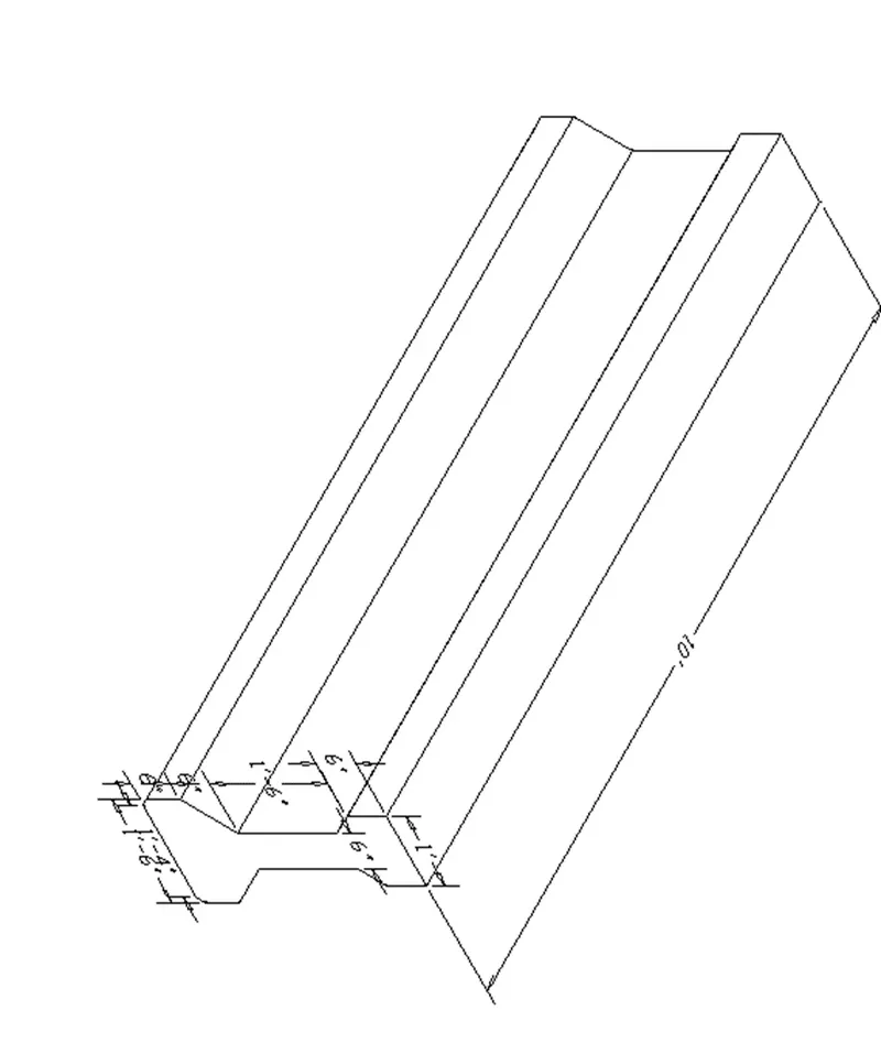
AIM: - To create the 3D model of AASTHO Type Grider in the AutoCAD in detail.
INTRODUCTION: -
- The three dimensional of AASTRO Type Grider was drawn in the AutoCAD using the different tools in the AutoCAD.
- 3D models are widely used anywhere in 3D graphics and CAD.
- Their use predates the widespread use of 3D graphics on personal computers.
- The 3d models are mainly preferable in civil engineering and when we design a building in the AutoCAD then creating 3d models should be must.
COMMANDS USED: -
- Line command
- Rectangle command
- UCS command
- Dimlinear command
- Region command
- Extrude command
- Substract command
- Box command
- Units command
- Dimstyle command
- 3Dface command
- 3Dorbit command
- Hide command
- Explode command
- Move command
- Copy command
- Dist command
- Rulesurf command
- Plan command
PROCEDURE: -
- First, we have to open the AutoCAD and set the units using the units' command.
- Next, we use the UCS command to set the directions of x-axis, y-axis and z-axis.
- Next, we have to draw a horizontal line with the length of 1'-4".
- Next, we draw the inclined line from the previous line.
- Next from the previous line we have to draw another vertical line upwards with the length of 6".
- Next again we draw the line from the previous line with the angle of 135 degrees with the length of 8".
- Draw the vertical line from the previous line with the length of 1'-3".
- Next, we draw another line from the previous line with the angle of 45 degrees with the length of 4".
- Next draw a vertical line from the previous line with the length of 6".
- Next, we use the mirror command and press enter, then select the right portion and place a cursor at the middle of the first line, then automatically right-side portion will be mirrored to the opposite side as shown in the below figure.
- Next use the plan command to change position to the x and y axis as shown in the below figure.
- Next, we need to put the dimensions for Evey part in the drawing as shown in the below figure.
- Next, we click the custom visual styles at the top left corner of the drawing screen, and select the shaded option in the custom visual styles.
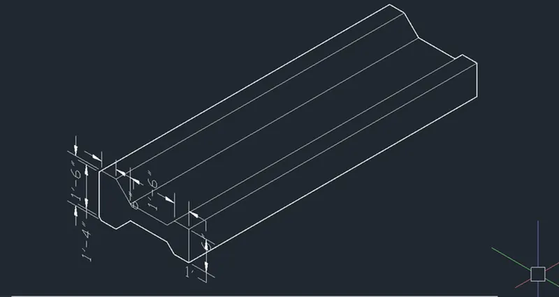
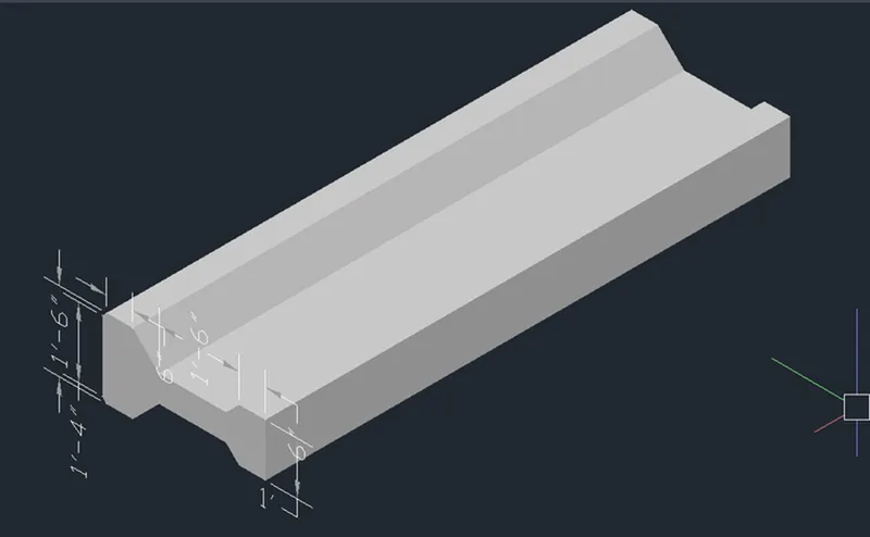
RESULT: -
- The given 3D model of the AASTHO Type Grider is drawn successfully in the AutoCAD in detail
- Create a 3d Model of a drop column with panel as shown in section and isometric view.
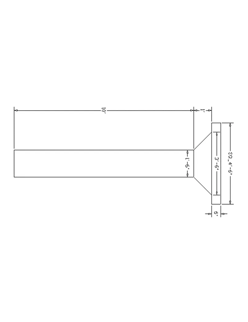
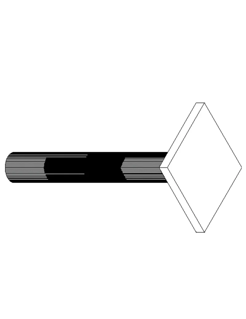
AIM: - To create the 3D model of a drop column with panel in the AutoCAD in detail.
INTRODUCTION: -
- The three dimensional of Drop column with panel was drawn in the AutoCAD using the different tools in the AutoCAD.
- 3D models are widely used anywhere in 3D graphics and CAD.
- Their use predates the widespread use of 3D graphics on personal computers.
- The 3d models are mainly preferable in civil engineering and when we design a building in the AutoCAD then creating 3d models should be a must.
COMMANDS USED: -
- Line command
- Rectangle command
- UCS command
- Dimlinear command
- Region command
- Extrude command
- Substract command
- Box command
- Units command
- Dimstyle command
- 3Dface command
- 3Dorbit command
- Hide command
- Explode command
- Move command
- Copy command
- Dist command
- Rulesurf command
- Plan command
PROCEDURE: -
- First, we have to open the AutoCAD and set the units using the units' command.
- Next, we use the UCS command to set the directions of x-axis, y-axis and z-axis.
- Next, we have to draw a line with the length of 10', next we have to draw another line from the previous line with the angle of 45 degrees and with the length of 1'.
- Next, we draw the straight line from the previous line with the length of 6".
- Next, we draw another line downwards from the previous line with the length of 4'-6".
- Next select the upper portion of the figure and then use mirror command to mirror it to the opposite side.
- Next, we draw the remaining inside the drawing as shown in the below figure.
- Next, we rotate the drop column in the different views using the 3Dorbit command as shown in the below figures.
- Next, we click the custom visual styles at the top left corner of the drawing screen, and select the shaded option in the custom visual styles.
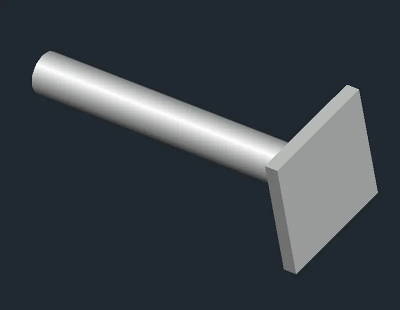
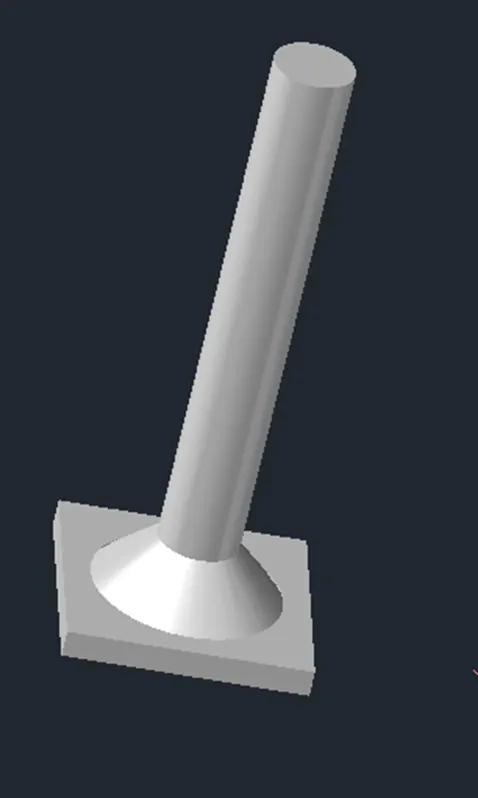
RESULT: -
- The given 3D model of the AASTHO Type Grider is drawn successfully in the AutoCAD in detail.
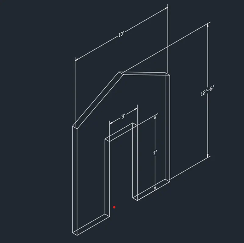
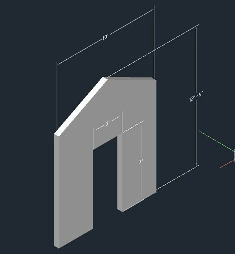
5. Create the 3d model of a wall as shown in Figure. Consider wall thickness as 9”.
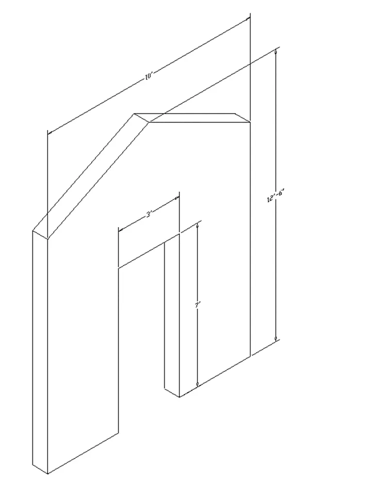
AIM: - To create the 3D model of a wall by assuming the wall thickness as 9" in the AutoCAD in detail.
INTRODUCTION: -
- The three dimensional of a wall is drawn in the AutoCAD using the different tools in the AutoCAD.
- 3D models are widely used anywhere in 3D graphics and CAD.
- Their use predates the widespread use of 3D graphics on personal computers.
- The 3D models are mainly preferable in civil engineering and when we design a building in the AutoCAD then creating 3d models should be must.
COMMANDS USED: -
- Line command
- Rectangle command
- UCS command
- Dimlinear command
- Region command
- Extrude command
- Substract command
- Box command
- Units command
- Dimstyle command
- 3Dface command
- 3Dorbit command
- Hide command
- Explode command
- Move command
- Copy command
- Dist command
- Plan command
PROCEDURE: -
- First, we have to open the AutoCAD and set the units using the units' command.
- Next, we use the UCS command to set the directions of x-axis, y-axis and z-axis.
- Next, we need to draw horizontally forward with the length of 10'.
- Next, we draw another line vertically upwards with the length of 10'.
- Next, we draw the line from the previous line with the angle of 125 degrees.
- Again, from the previous line we draw another line with the angle of 225 degrees and with the length of 5'.
- Next join the line from the first line to the last line, as shown in the below figure
- Next again we draw the rectangle inside the wall as shown in the figure
- Next, we use the extrude command to extrude the wall with the thickness of 9".
- Next again we use the extrude command to extrude the inside rectangle with the thickness of 9', as shown in the below figure.
- Next, we subtract the door part from the wall using the subtract command as shown in the below figure
- Next, we have to use the 3D face command to hide the inner part, and also, we use hide command to hide them as shown in the below figure.
- Next, we put the dimensions for every part in the drawing using the dim linear command as shown in the below figure.
- Next, we click the custom visual styles at the top left corner of the drawing screen, and select the shaded option in the custom visual styles.
RESULT: -
- The given 3D model of a wall is drawn successfully in the AutoCAD in detail.