Creating various 3D Models like Furniture, Footing, Girder, Column drop with panel and Gable Wall in AutoCad
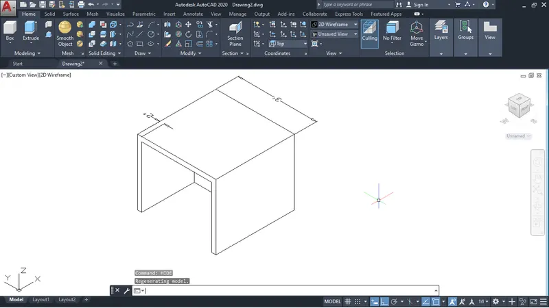
Aim: Create a 3D Furniture element as shown in the Figure. Assume dimensions which are missing.
- I am using imperial template
- Set unit to Engineering by command-UN
- After setting the unit we can go to default view from view-cube. how we can do this setting take your mouse on view-cube and hover arround the cube you see the home like anime click on that and now you are in the default view.
- now we have to go to 3d modeling how do we do that
- We can go to workspace setting and change into 3d basic or 3d modeling or we can use command- WSCURRENT to change into 3d modeling
Now after doing all setting we draw
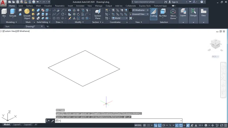
- I draw rectangle (3'x3') by command-REC as you can see below fig.
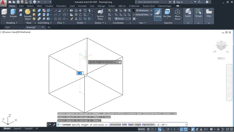
- Now I use command-EXTRUDE OR EXT
- Select the object- i select the rectangle
- Now give the height-2'6"
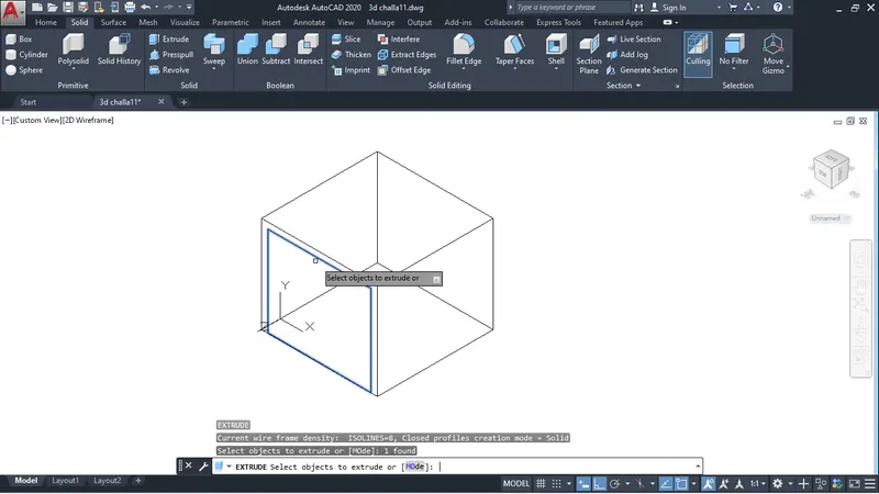
- After that I use command-UCS
- select the face of rectangle in which i want to draw as you can see in below fig.
- after selecting the face I draw another rectangle inside that face but rectangle is 2" space between left,right, top sides
- Now Extrude the rectangle
- After Extrusion it going to look like as below fig.
- Now subtract them by command-SUBTRACT or SUB
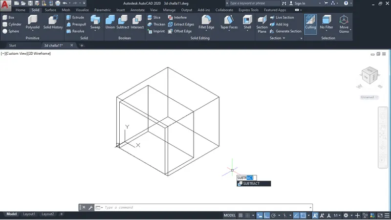
- When you give the subtract command it going to say select the object you select the object from which you want subtract and press enter as you can see fig below
- then again it say select object you select that object which you want subtract and press enter
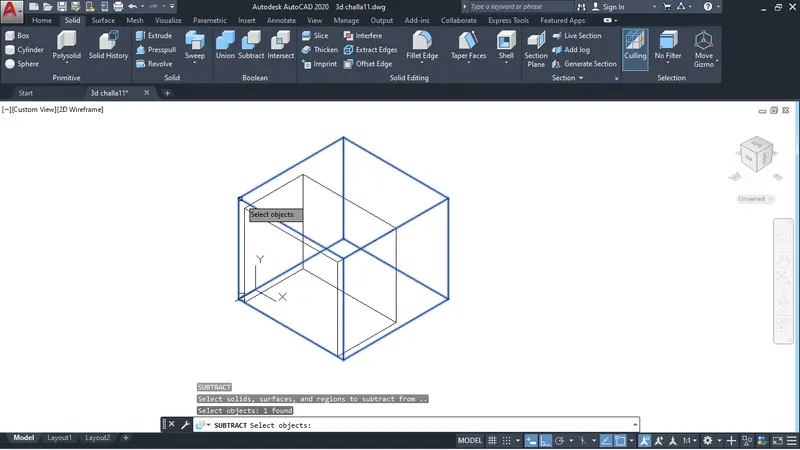
- after subtracting it look like as below fig.
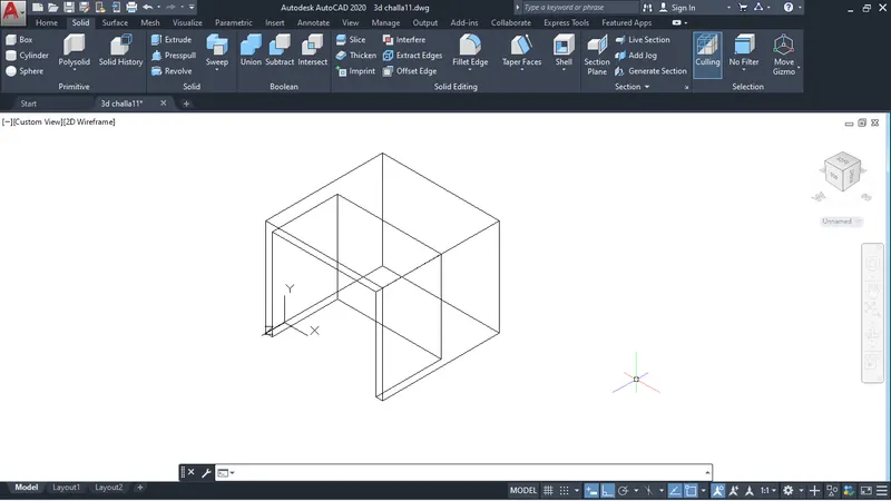
- Now give the command-HIDE
- when give the hide command it look like as below fig.
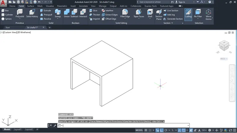
- Now you can give the dimension by command-DIMLIN
Aim: Create the 3d Model of an Isolated footing as shown in Figure.
- I am using imperial template
- Set unit to Engineering by command-UN
- now go to top view
- draw rectangle (3'x3') by command-REC
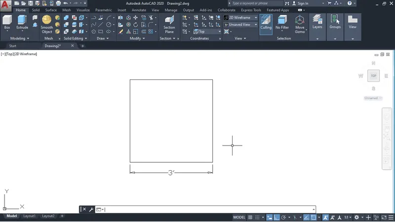
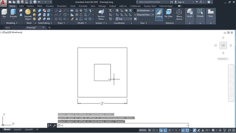
- Now take offset by command-O
- give the offset distance 1'
- select the rectangle take inside the offset as you can see below fig.
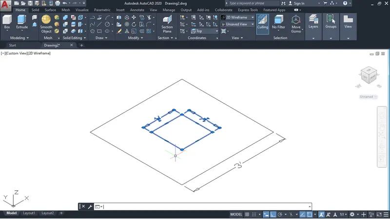
- now go to default view
- move the inside rectangle in the z-axis at distance 2'
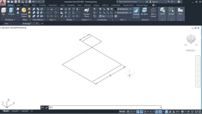
- Now Extrude the rectangle as youcan see in fig below.
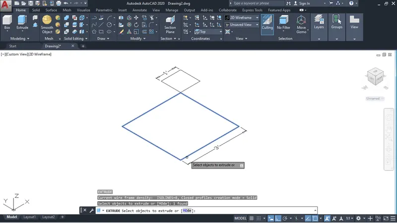
- give the extrusion height 6"
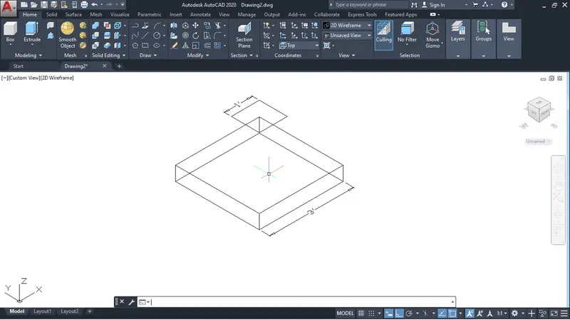
- I used line tool as you can see below fig.
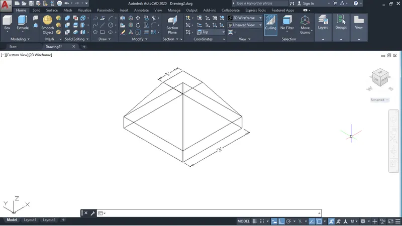
- make the the region
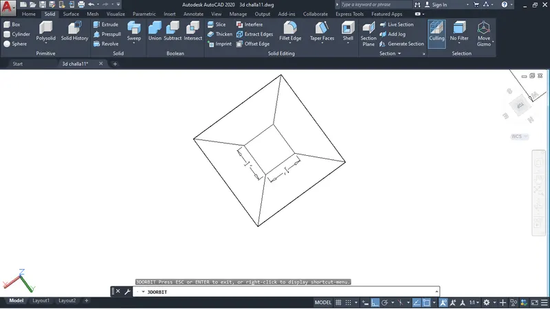
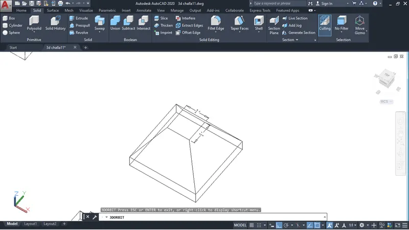
after making region use Hide command
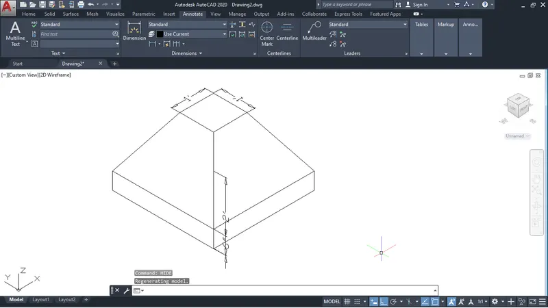
Aim: Create the 3D view of the AASTHO Type Girder.
- I am using imperial template
- Set unit to Engineering by command-UN
- now go to top view
now draw the fig.as below
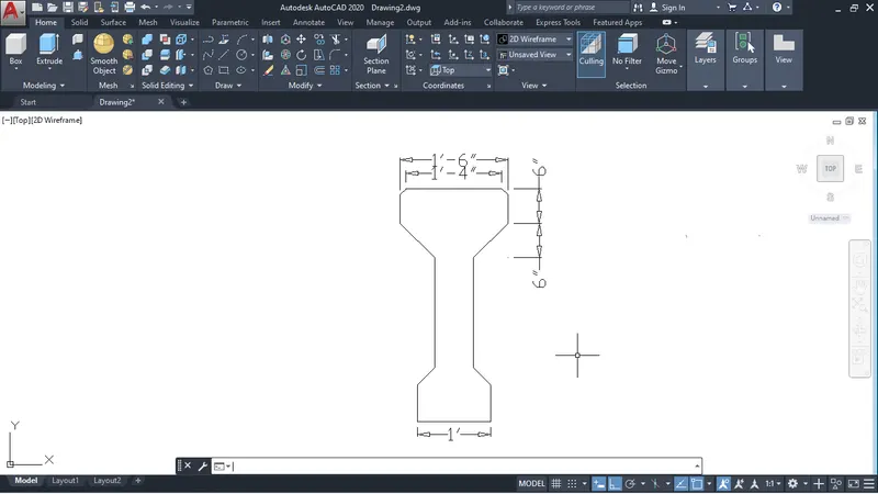
- now go to default view
- make the region by command-REG
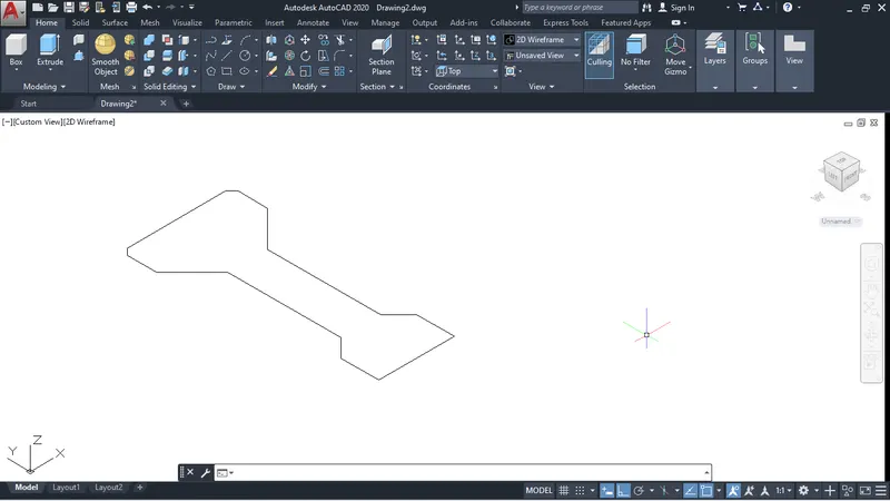
- Extrude it at distance 10' in z-axis
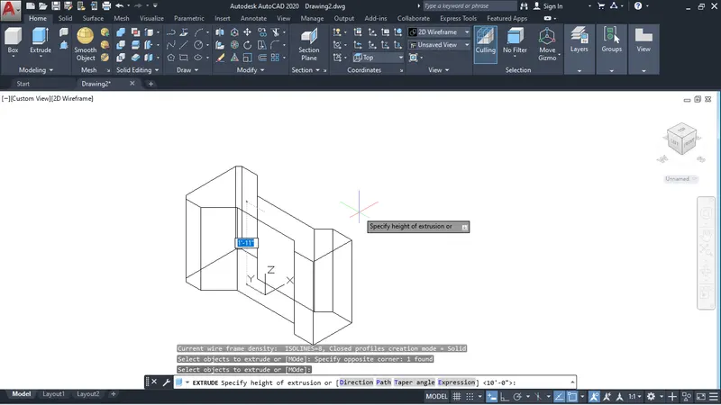
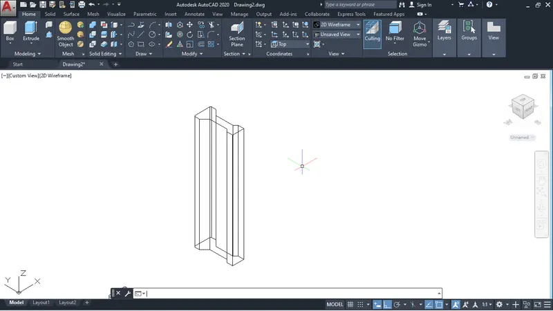
- used 3d Rotate command
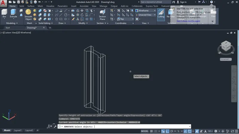
- select the object which you want to rotate
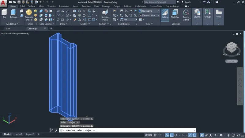
- specify the base point as you can see below fig.
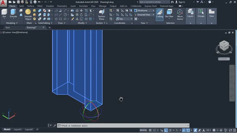
- rotate it in y-axis
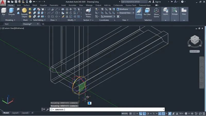
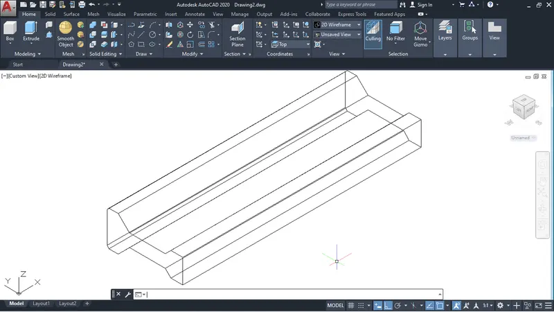
- use dimension tool for the measurement
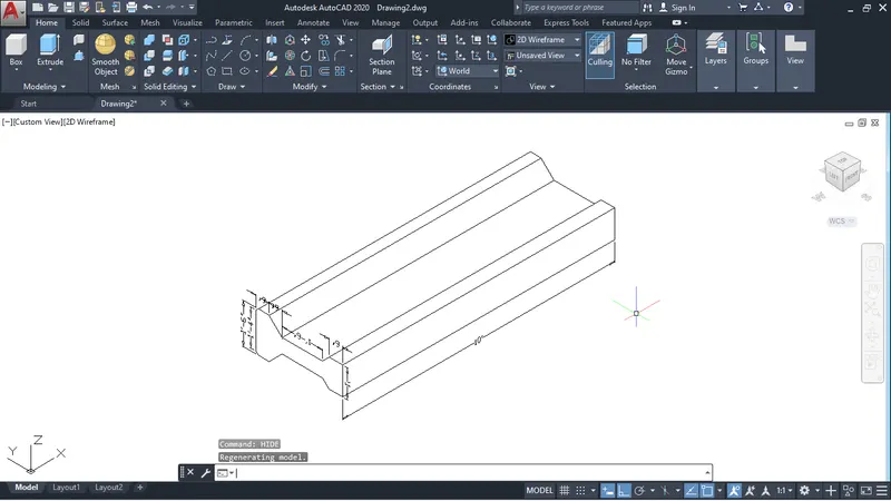
Aim: Create a 3d Model of a drop column with panel as shown in section and isometric view.
- I am using imperial template
- Set unit to Engineering by command-UN
- now go to top view
we can draw this in top view using rectangle and line tool
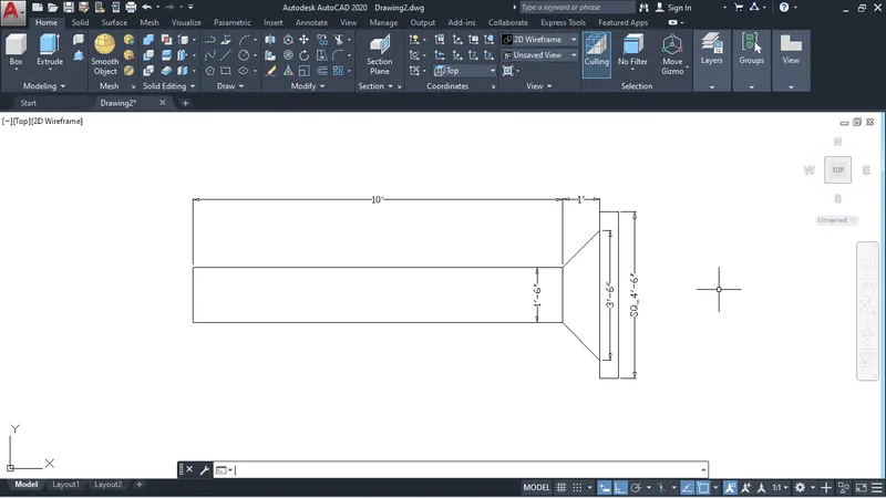
- now we draw this in 3d modeling
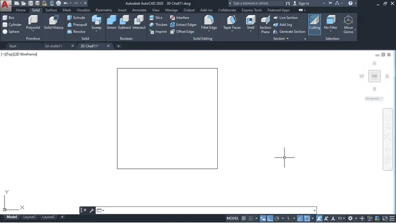
- in top view we draw rectangle (4'6"x4'6")
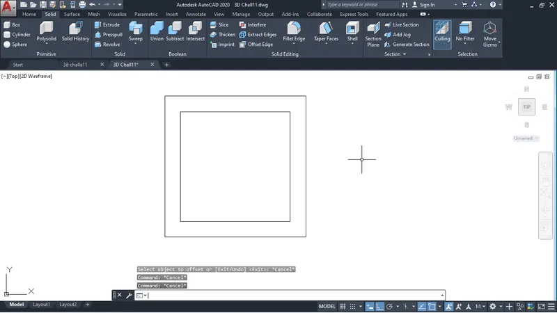
- take the offset of 6"
- now go to default view
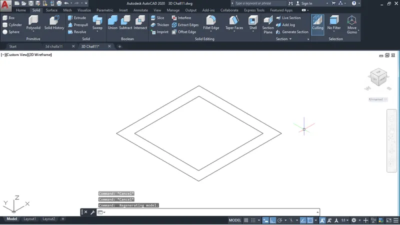
- move the inside rectangle 6" in z-axis
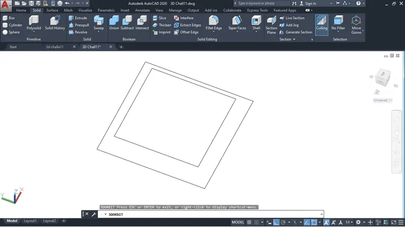
- now take Extrude the below rectangle at hieght 6"
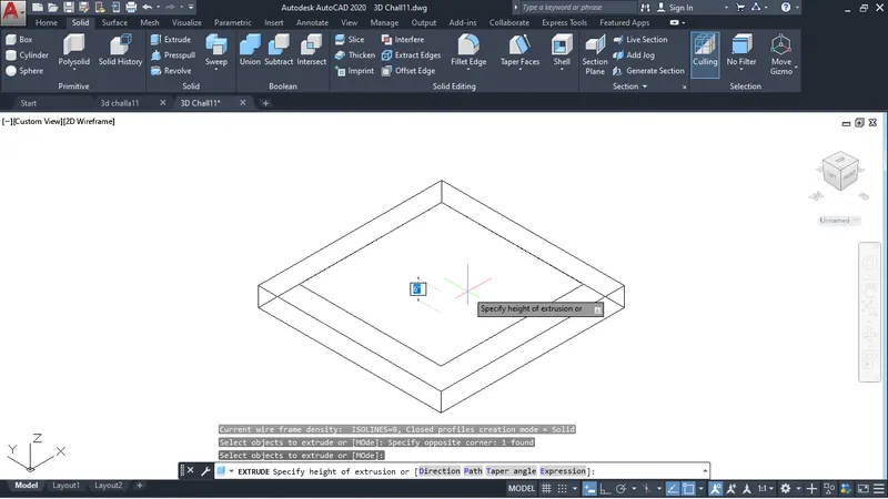
- Now Extrude the inside rectangle at taper angle- 45 and height 1'
- now go to command-Solidediting
- go to face select Extrude
- select the face which you want extrude and give the height 10'
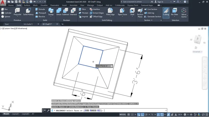
- after that it look like as below fig.
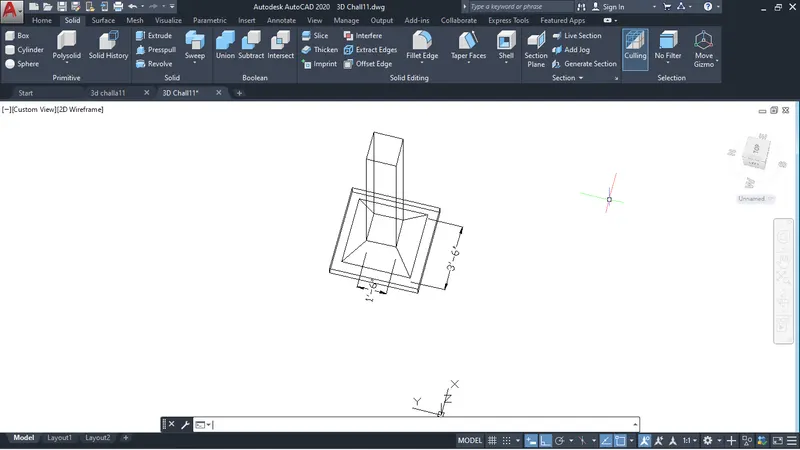
- now go to Hide command
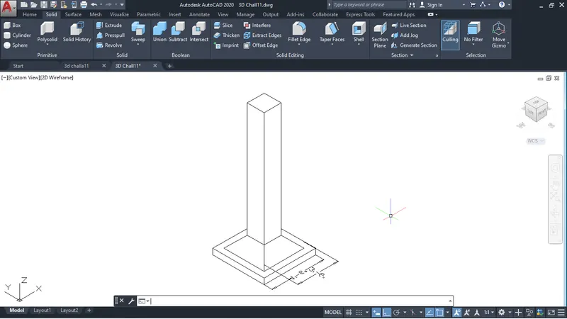
- Now draw this in isometric view
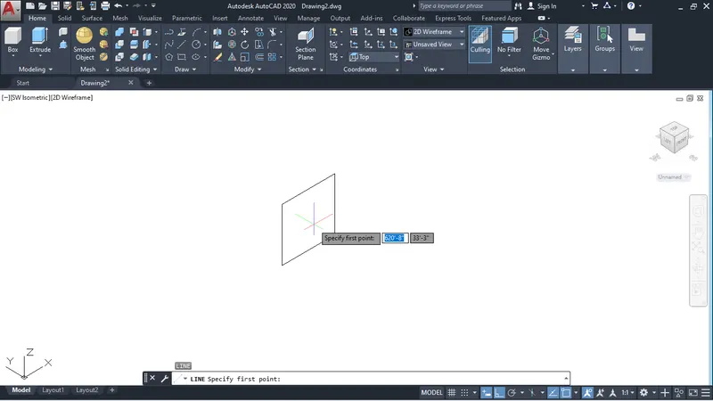
- after drawing as shown in below fig.
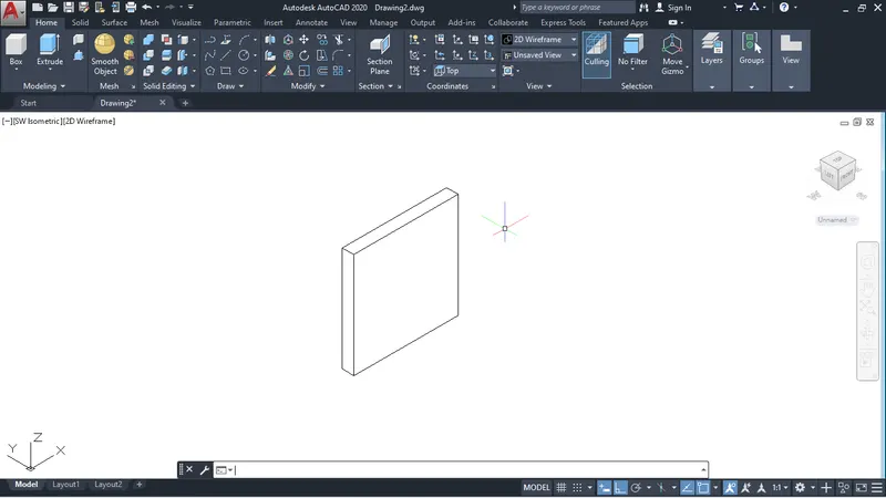
- after that i used cylinder elliptical
- increase the surftres 10
- and used hide command.
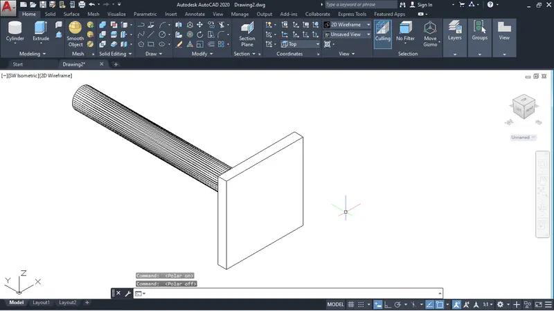
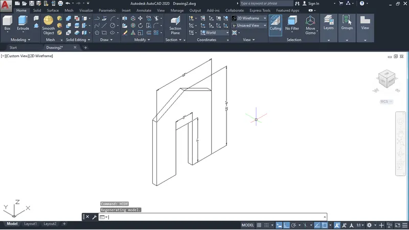
Aim: Create the 3d model of a wall as shown in Figure. Consider wall thickness as 9”.
- I am using imperial template
- Set unit to Engineering by command-UN
- I go default view
- I used the line tool and draw line 10' in x-axis direction
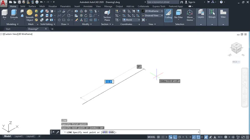
- now draw line 10' in z-axis again in same direction 2'6" line
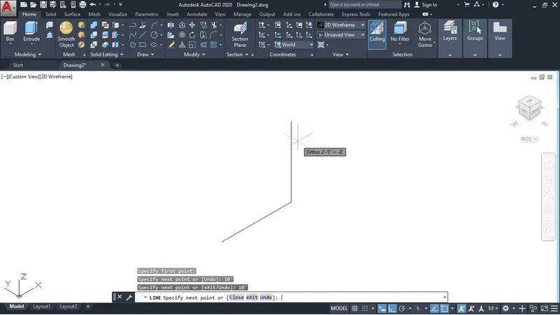
- then the draw line -10' in x-axis
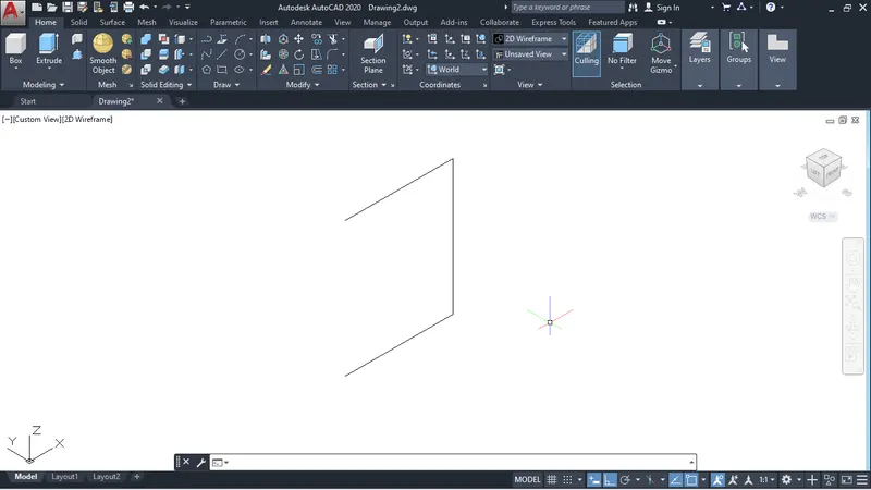
- now take line tool draw from initial point 10' in z-axis

- now take line in middle of top line
- from top middle point draw line in right side line at point where right side at 10'
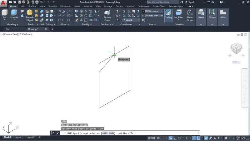
- after trim the line you will get fig as below
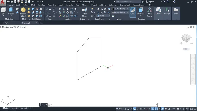
- after make the region of above fig.
- Extrude it 9"
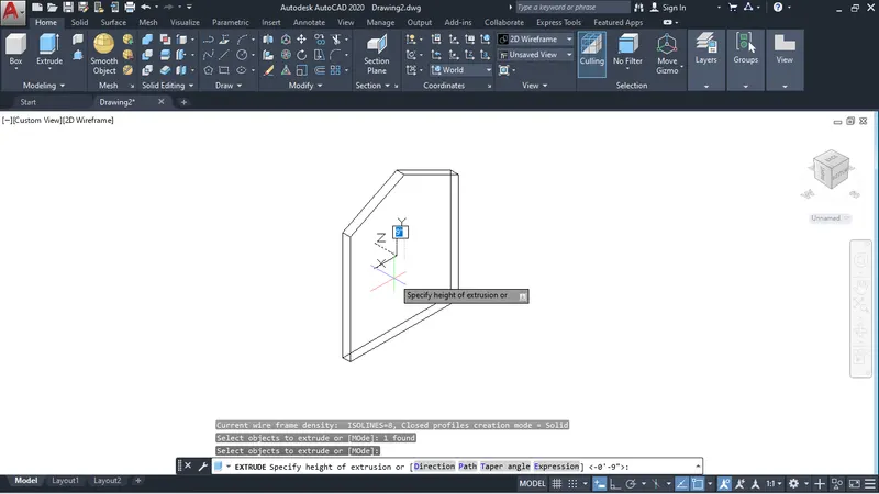
- for the draw rectangle (9"x3') at outside
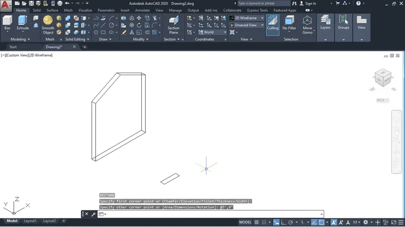
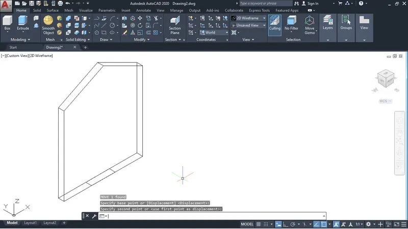
- move the rectangle from middle point
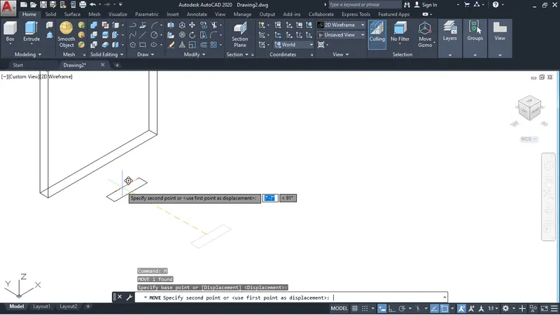
- put it in middle point of bottom face
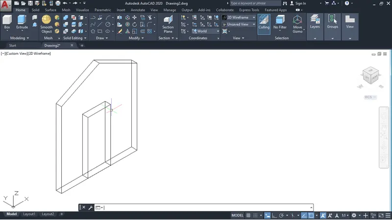
- Extrude that rectangle at height 7'
- Now Subtract it by using command-SUB
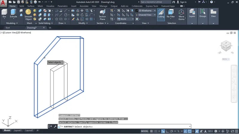
- after subtracting it look like as below fig.
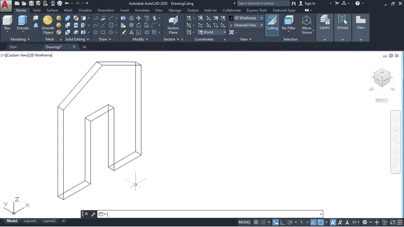
- Use the dimension tool for measurment
- and use the hide command fig will look like as below fig.