Creating various 3D Models like Furniture, Footing, Girder, Column drop with panel and Gable Wall in AutoCad
04/07/21
Answer
1. Create a 3D Furniture element as shown in the Figure. Assume dimensions that are missing.
Aim
Create a 3D Furniture element of the project.
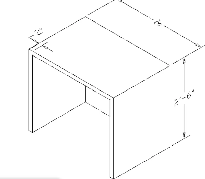
Procedure
STEP-1 opening to the AutoCAD software and entering the workspace.
STEP-2 Setting limits >specify lower-left corner:0,0
STEP-3 specify upper-left corner:100,100
STEP-4 Set>units>Demical>intersectional scale>mm
STEP-5 Limmax>100,100
STEP-6 Polysolid command>it helps to create a solid boundary to the defined height.
STEP-7 width, length option can be set for the required form
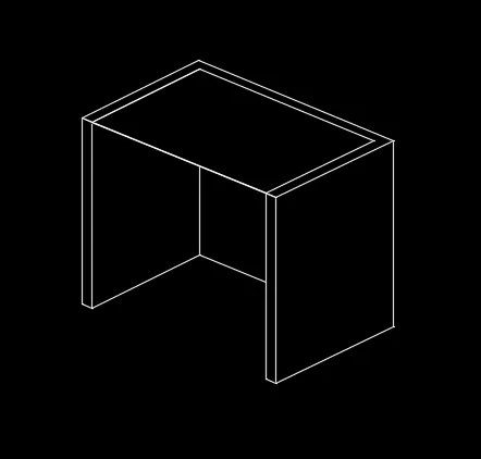
STEP-8 3dface command>help as to form the solid form
STEP-9 3dorbit command> helps to rotate the object at the required angle.
STEP-10 shaded view> help to find the 3D form.
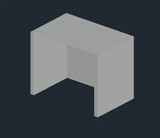
STEP-11 close the entire object
STEP-12 and save the file for feature use.
2. Create the 3d Model of an Isolated footing as shown in Figure.
Aim
Create the 3d Model of an Isolated footing of the project.
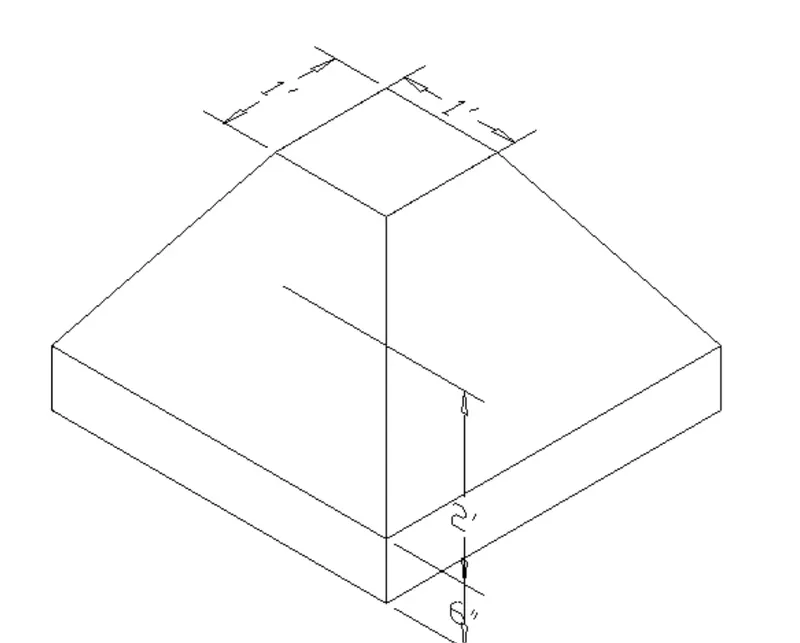
Procedure
STEP-1 opening to the AutoCAD software and entering the workspace.
STEP-2 Setting limits >specify lower-left corner:0,0
STEP-3 specify upper-left corner:100,100
STEP-4 Set>units>Demical>intersectional scale>mm
STEP-5 Limmax>100,100
STEP-6 Polysolid command>it helps to create a solid boundary to the defined height.
STEP-7 cube command> help to extrude the box in the defined form.
STEP-8 Extrude command> help as to extrude in the defined forms
STEP-9 width, length option can be set for the required form
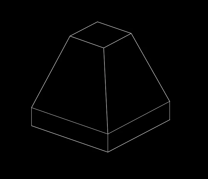
STEP-10 3dface command>help as to form the solid form
STEP-11 3dorbit command> helps to rotate the object at the required angle.
STEP-12 shaded view> help to find the 3D form.
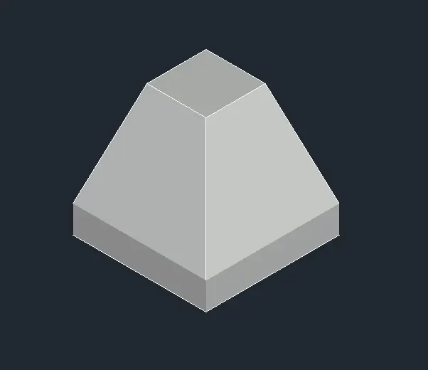
STEP-13 close the entire object
STEP-14 and save the file for feature use.
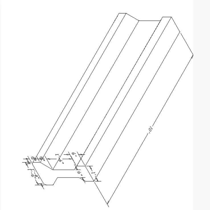
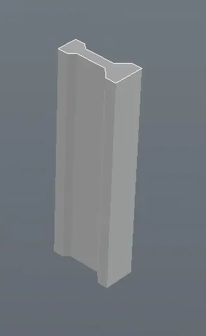
3. Create the 3D view of the AASTHO Type Girder.
Aim
Create the 3D view of the AASTHO Type Girder of the project.
Procedure
STEP-1 opening to the AutoCAD software and entering the workspace.
STEP-2 Setting limits >specify lower-left corner:0,0
STEP-3 specify upper-left corner:100,100
STEP-4 Set>units>Demical>intersectional scale>mm
STEP-5 Limmax>100,100
STEP-6 Polysolid command>it helps to create a solid boundary to the defined height.
STEP-7 cube command> help to extrude the box in the defined form.
STEP-8 Extrude command> help as to extrude in the defined forms
STEP-9 width, length option can be set for the required form
STEP-10 3dface command>help as to form the solid form
STEP-11 3dorbit command> helps to rotate the object at the required angle.
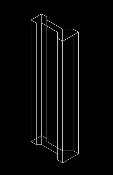
STEP-12 shaded view> help to find the 3D form.
STEP-13 close the entire object
STEP-14 and save the file for feature use.
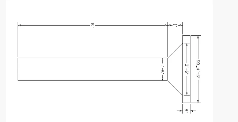
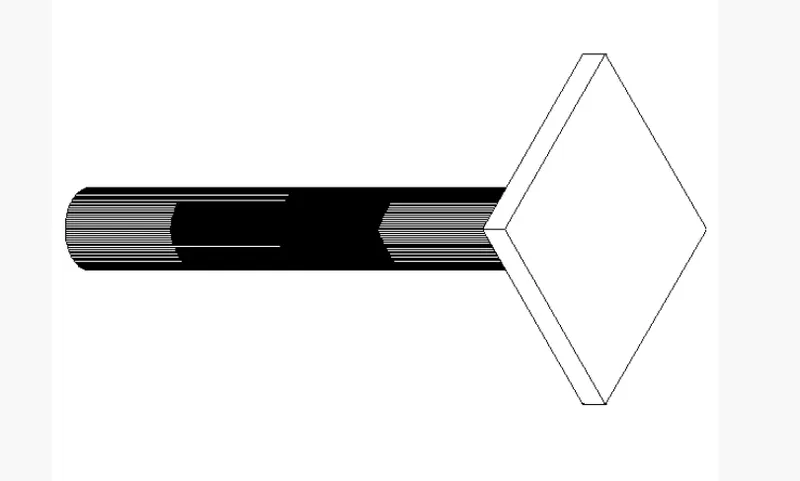
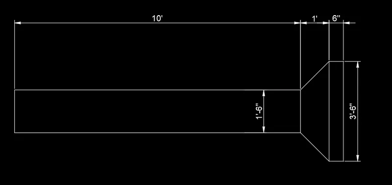
4. Create a 3d Model of a drop column with the panel as shown in section and isometric view.
Aim
Create a 3d Model of a drop column with the panel of the project.
Procedure
STEP-1 opening to the AutoCAD software and entering the workspace.
STEP-2 Setting limits >specify lower-left corner:0,0
STEP-3 specify upper-left corner:100,100
STEP-4 Set>units>Demical>intersectional scale>mm
STEP-5 Limmax>100,100
STEP-6 Polysolid command>it helps to create a solid boundary to the defined height.
STEP-7 cube command> help to extrude the box in the defined form.
STEP-8 Extrude command> help as to extrude in the defined forms
STEP-9 width, length option can be set for the required form
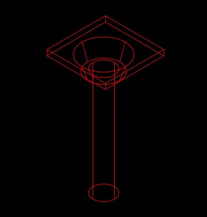
STEP-10 3dface command>help as to form the solid form
STEP-11 3dorbit command> helps to rotate the object at the required angle.
STEP-12 shaded view> help to find the 3D form.
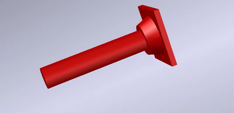
STEP-13 close the entire object
STEP-14 and save the file for feature use.
5. Create the 3d model of a wall as shown in Figure. Consider wall
Aim
Create the 3d model of a wall of the project.
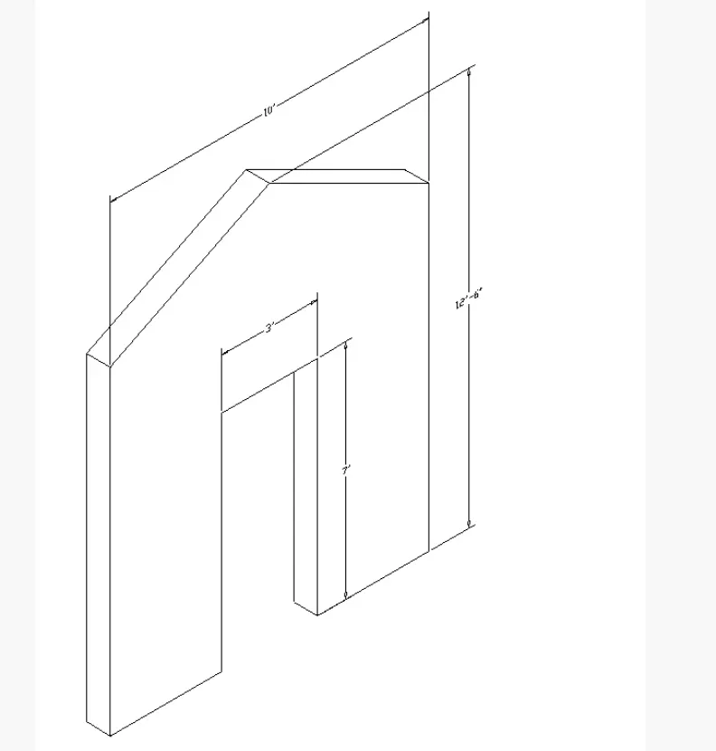
Procedure
STEP-1 opening to the AutoCAD software and entering the workspace.
STEP-2 Setting limits >specify lower-left corner:0,0
STEP-3 specify upper-left corner:100,100
STEP-4 Set>units>Demical>intersectional scale>mm
STEP-5 Limmax>100,100
STEP-6 Polysolid command>it helps to create a solid boundary to the defined height.
STEP-7 cube command> help to extrude the box in the defined form.
STEP-8 Extrude command> help as to extrude in the defined forms
STEP-9 width, length option can be set for the required form
STEP-10 3dface command>help as to form the solid form
STEP-11 3dorbit command> helps to rotate the object at the required angle.
STEP-12 shaded view> help to find the 3D form.
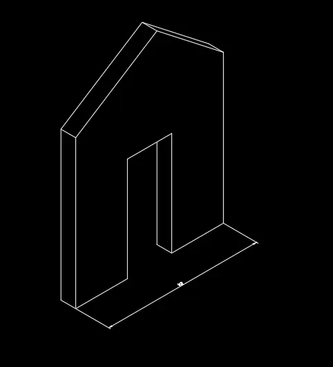
STEP-13 close the entire object
STEP-14 and save the file for feature use.