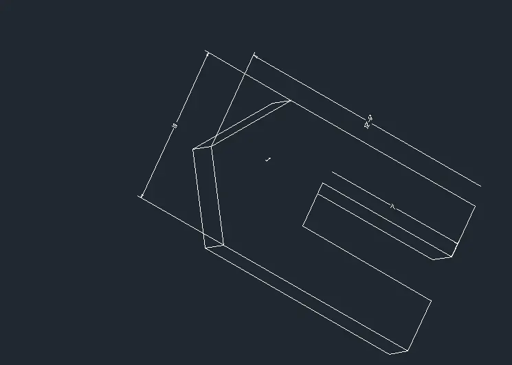
Creating various 3D Models like Furniture, Footing, Girder, Column drop with panel and Gable Wall in AutoCad
AIM:- to create 3d model and view
COMMANDS USED:-
- extrude
- OFFSET
- UCS
- box
- union
- subtract
- move
- 3d orbit
- loft
- sweep
- cone
- region
procedure:-
- open the autocad ,click on workspace switching and change it to 3d modelling and click on the home buttonnear the view cube
- create a box by clicking from the toolbar or box command click on length give the length as 3' and width 2'6"
- type plan command so that front face is aligned corrctly
- move the rectangle to the line drawn earlier 2" from the right side of front view . by rectangle command draw a rectangle of dimension 32" and 2'4"
- move the rectangle to the line drawn earlier 2" from the right of the face
- DELETE the line created earlier now with command 3d orbit
- select the rectangle
- extrude the rectangle to z axis 2'4" leaving 2" thickness
- dimensions are given by dim linear
result:- THE 3d model of furniture element is created
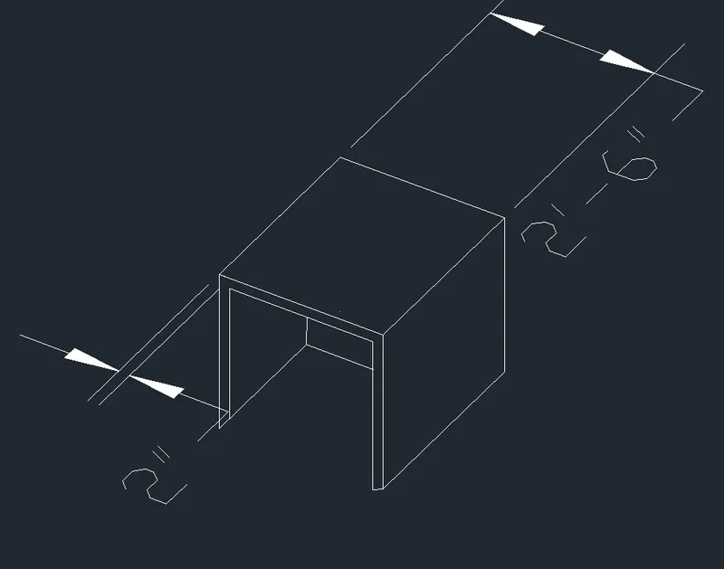
AIM:- to create 3d model of isolated footing
COMMANDS USED:-
- extrude
- OFFSET
- UCS
- box
- union
- subtract
- move
- 3d orbit
- loft
- sweep
- cone
- region
procedure:-
- open the autocad ,click on workspace switching and change it to 3d modelling and click on the home buttonnear the view cube
- create a box by clicking from the toolbar or box command click on length give the length as 3' and width 2'6"
- type plan command so that front face is aligned corrctly
- move the rectangle to the line drawn earlier 2" from the right side of front view . by rectangle command draw a rectangle of dimension 32" and 2'4"
- move the rectangle to the line drawn earlier 2" from the right of the face
- DELETE the line created earlier now with command 3d orbit
- select the rectangle
- extrude the rectangle to z axis 2'4" leaving 2" thickness
- dimensions are given by dim linear
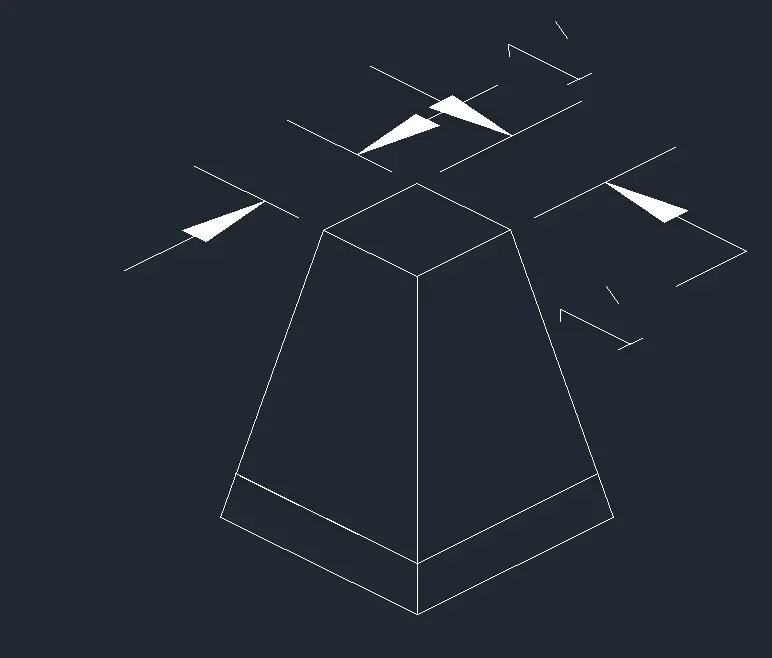
AIM:- TO create 3d model of AASTO type girder using auto cad 3d
COMMANDS USED:-
- extrude
- OFFSET
- UCS
- box
- union
- subtract
- move
- 3d orbit
- loft
- sweep
- cone
- region
PROCEDURE:-
- open the autocad ,click on workspace switching and change it to 3d modelling and click on the home buttonnear the view cube
- create a box by clicking from the toolbar or box command click on length give the length as 3' and width 2'6"
- type plan command so that front face is aligned corrctly
- move the rectangle to the line drawn earlier 2" from the right side of front view . by rectangle command draw a rectangle of dimension 32" and 2'4"
- move the rectangle to the line drawn earlier 2" from the right of the face
- DELETE the line created earlier now with command 3d orbit
- select the rectangle
- extrude the rectangle to z axis 2'4" leaving 2" thickness
- dimensions are given by dim linear
RESULT:-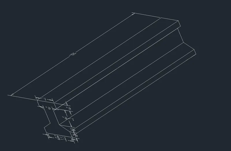
AIM:- TO draw the 3d model of a drop column with panel section and show its isometric view
cOMMANDS USED:-
- extrude
- OFFSET
- UCS
- box
- union
- subtract
- move
- 3d orbit
- loft
- sweep
- cone
- region
PROCEDURE:-
- open the autocad ,click on workspace switching and change it to 3d modelling and click on the home buttonnear the view cube
- create a box by clicking from the toolbar or box command click on length give the length as 3' and width 2'6"
- type plan command so that front face is aligned corrctly
- move the rectangle to the line drawn earlier 2" from the right side of front view . by rectangle command draw a rectangle of dimension 32" and 2'4"
- move the rectangle to the line drawn earlier 2" from the right of the face
- DELETE the line created earlier now with command 3d orbit
- select the rectangle
- extrude the rectangle to z axis 2'4" leaving 2" thickness
- dimensions are given by dim linear
RESULT:-
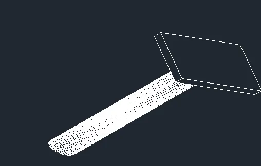
AIM:- to draw a 3d model of wall
cOMMANDS USED:-
- extrude
- OFFSET
- UCS
- box
- union
- subtract
- move
- 3d orbit
- loft
- sweep
- cone
- region
PROCEDURE:-
- open the autocad ,click on workspace switching and change it to 3d modelling and click on the home buttonnear the view cube
- create a box by clicking from the toolbar or box command click on length give the length as 3' and width 2'6"
- type plan command so that front face is aligned corrctly
- move the rectangle to the line drawn earlier 2" from the right side of front view . by rectangle command draw a rectangle of dimension 32" and 2'4"
- move the rectangle to the line drawn earlier 2" from the right of the face
- DELETE the line created earlier now with command 3d orbit
- select the rectangle
- extrude the rectangle to z axis 2'4" leaving 2" thickness
- dimensions are given by dim linear
RESULT:-