Creating various 3D Models like Furniture, Footing, Girder, Column drop with panel and Gable Wall in AutoCad
1. Aim: To create the 3D furniture element.
Introduction: To create the 3d furniture element as in the given figure.
Procedure:
- First we have to set the limits for 3d drawing by using un command.
- And also have to set the limits by using limmax command.
- Then the drawing space area has to change to 3d module as 3D modelling.
- Now take the rectangle command, and draw the rectangle by using the x,y and z dimensions.
- Now extrude the rectangle area for outer area by assuming some dimensions as attached below.
-
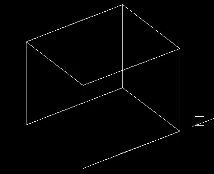
- Then after taking the outer dimensions, take offset distance of 2" and draw the rectangle for the front portion as shown in the figure.
- Then by using trim command trim the remaining area which is not used in the drawing.
- Now we have to give the dimensions whereever given in the drawing.
- For giving te measurements, we need to change the UCS icon for proper dimensioning.
- Then we have drag the UCS icon wherever we are taking the dimensions.
- In the same way we have to give the dimensions for the drawing and the final drawing is attached in the result.
Result:
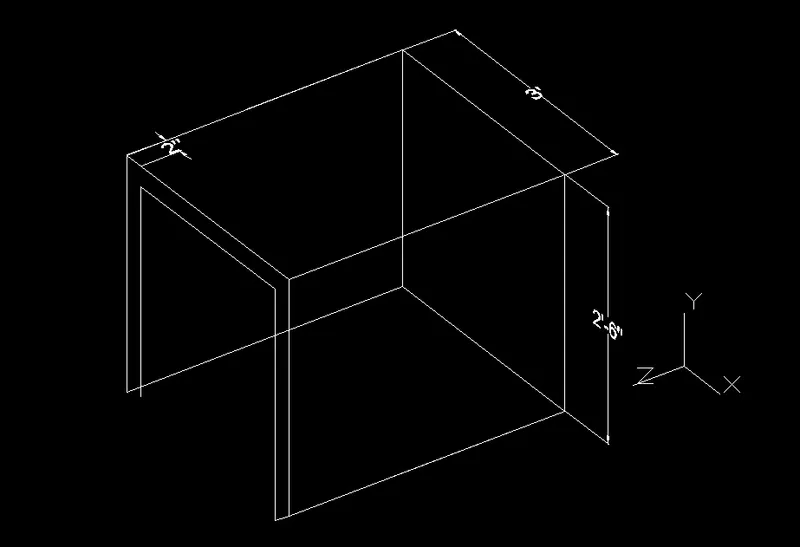
2. Aim: To create the 3D module of an Isolated footing.
Introduction: To create the 3D module of an isolated footing as in the given figure.
Procedure:
- First we have to set the limits for 3d drawing by using un command.
- And also have to set the limits by using limmax command.
- Then the drawing space area has to change to 3d module as 3D modelling.
- Now take the rectangle command, and draw the rectangle by using the x,y and z dimensions.
- Now extrude the rectangle area for outer area by assuming some dimensions as attached below.
-
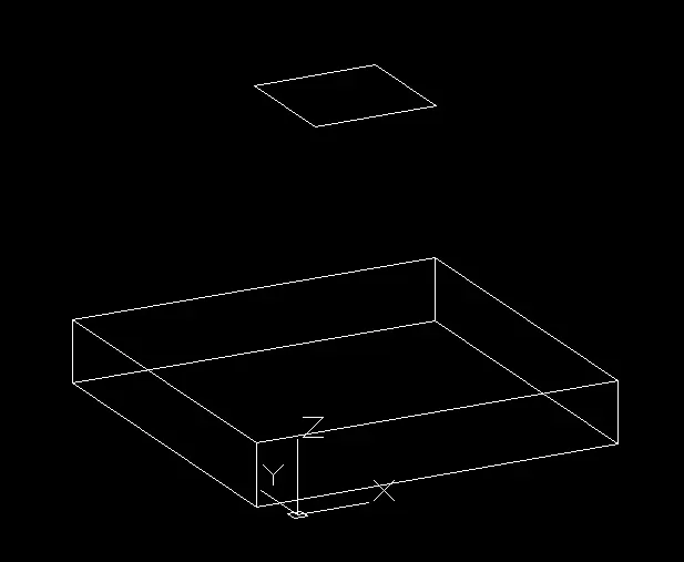
- Take a small rectangle with the given dimensions in the figure from the centre of the rectangle.
- And then move the small rectangle to some disstance height as in the given drawing.
- Now by using line command, draw the lines by connecting the 2 rectangles.
- Now we have to give the dimensions whereever given in the drawing.
- For giving te measurements, we need to change the UCS icon for proper dimensioning.
- Then we have drag the UCS icon wherever we are taking the dimensions.
- In the same way we have to give the dimensions for the drawing and the final drawing is attached in the result.
Result:
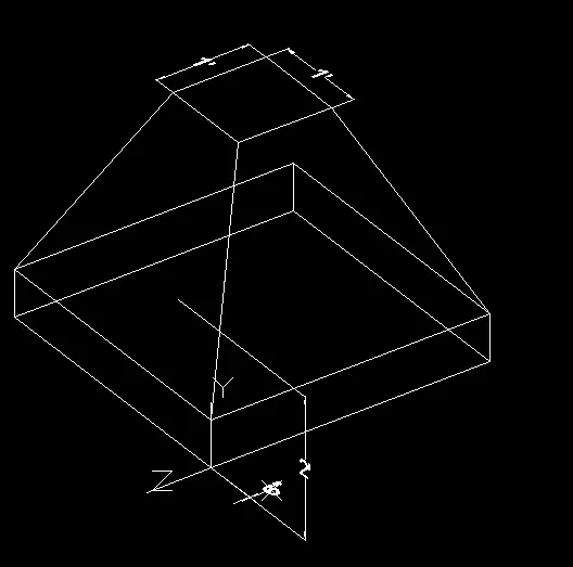
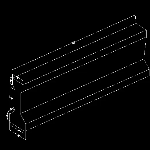
3. Aim: To create the 3D view of AASTHO type girder.
Introduction: To create the 3D view of AASTHO type girder which is in the given attachment.
Procedure:
- First we have to set the limits for 3d drawing by using un command.
- And also have to set the limits by using limmax command.
- Then the drawing space area has to change to 3d module as 3D modelling.
- Now take the front portion area with the dimensions which is in the given figure as attached below.
-
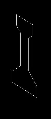
- Then after taking the front view portion, then we need to draw the lines to extend.
- From every point we need to draw the line t some distance which is in the given figure.
- After extending of some portion every line should be draw to some distance upto 10'.
- Then the drawing portion is ready as in the given attachement.
-
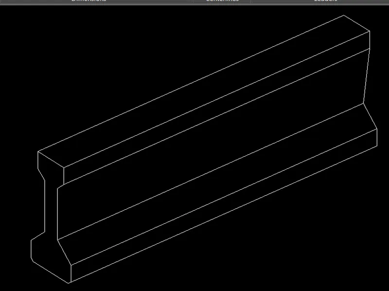
- Now by using line command, draw the lines by connecting the 2 lines.
- Now we have to give the dimensions whereever given in the drawing.
- For giving te measurements, we need to change the UCS icon for proper dimensioning.
- Then we have drag the UCS icon wherever we are taking the dimensions.
- In the same way we have to give the dimensions for the drawing and the final drawing is attached in the result.
Result:
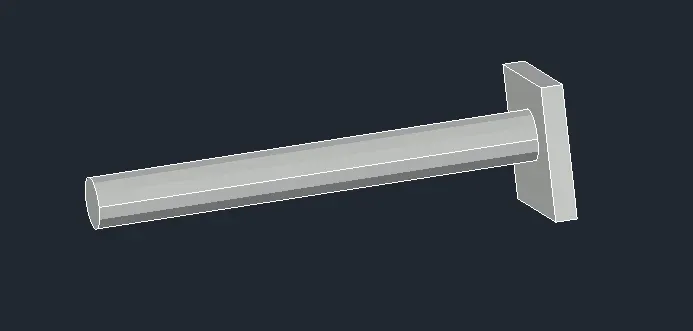
4. Aim: To create the 3d model of a drop column with panel.
Intorduction: To create the 3d model of a drop column with panel as shown in section and isometric view.
Procedure:
- First we have to set the limits for 3d drawing by using un command.
- And also have to set the limits by using limmax command.
- Then the drawing space area has to change to 3d module as 3D modelling.
- Take the retangle and draw the rectangle and change the view angle.
- Now take the front portion area with the assumed dimensions which is in the given figure as attached below.
-
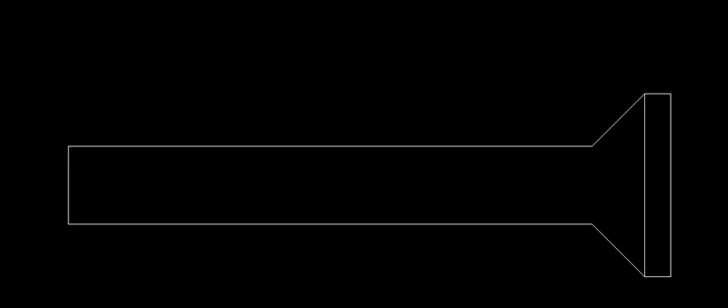
- Now by using line command, draw the lines by connecting the 2 lines.
- Now we have to give the dimensions whereever given in the drawing.
- For giving te measurements, we need to change the UCS icon for proper dimensioning.
- Then we have drag the UCS icon wherever we are taking the dimensions.
- In the same way we have to give the dimensions for the drawing and the final drawing is attached in the result.
Result:
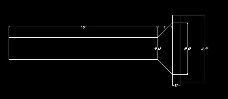
- Now we have take the section portion of the drawing which is given in the attachement.
- We have to assume the dimensions for the section portion.
- Then draw the outer rectangle by using rectangle command.
-
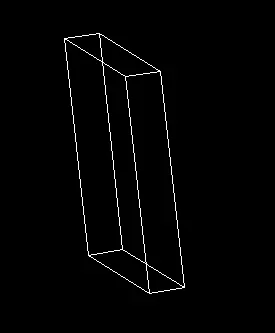
- After the rectangle, extrude the rectangle to some portion by assumiing the dimension in the plan.
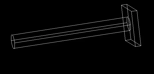
- The we need to draw the circle and drag the circle to the rectangle portion.
- Finally the drawing should be in the shaded area and final drawing is attched below in the result.
-
Result:
5. Aim: To create the 3d model of wall as in the given figure.
Introduction: To create the 3d model of wall as in the given figure by considering wall thickness of 9".
Procedure:
- First we have to set the limits for 3d drawing by using un command.
- And also have to set the limits by using limmax command.
- Then the drawing space area has to change to 3d module as 3D modelling.
- Now take the rectangle command, and draw the rectangle by using the x,y and z dimensions.
- Now extrude the rectangle area for outer area by assuming some dimensions.
- Now draw the wall thickness to the rectangle as 9" wall is given in the attchment.
-
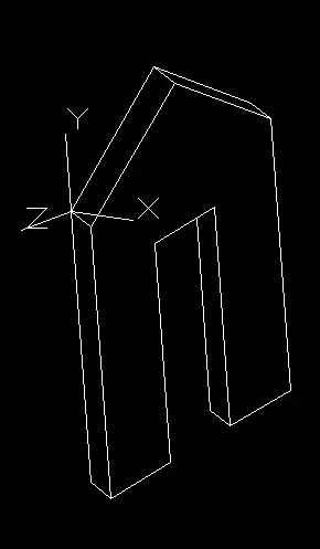
- Now by using line command, draw the lines by connecting the 2 lines.
- Now we have to give the dimensions whereever given in the drawing.
- For giving te measurements, we need to change the UCS icon for proper dimensioning.
- Then we have drag the UCS icon wherever we are taking the dimensions.
- In the same way we have to give the dimensions for the drawing and the final drawing is attached in the result.
-
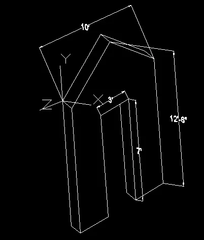
Result: