Creating various 3D Models like Furniture, Footing, Girder, Column drop with panel and Gable Wall in AutoCad
1) AIM: To create a 3D Furniture element as shown in the Figure.
PROCEDURE:
- Open cad application in the pc and set all the limits required.
- Set the units as required for drawing. Set units in Engineering and scale in Inches.
- Now here we have to change the model space from Drafting to 3D modeling.
- Once you go for 3d modeling a new axis will appear in the ucs icon.
- Here in that new axis 'Z' the all the thickness of extrude goes.
- Draw a rectangle in x z plane. With the mentioned dimensions.
- Use the offset command to show the thickness.
- Now once the full drawing is completed now type 3F in the command box.
- It indicates to select the first point, and then second likely we have to select the four points.
- Once the four corners are specified it becomes the surface.
- Here we can only go for four points or corners. Irregular shapes are cannot be done in this method.
- To check the surfaces are done correctly now type hide in command box then the lines will disappear.
- If wanted can be shifted to different views.
RESULT: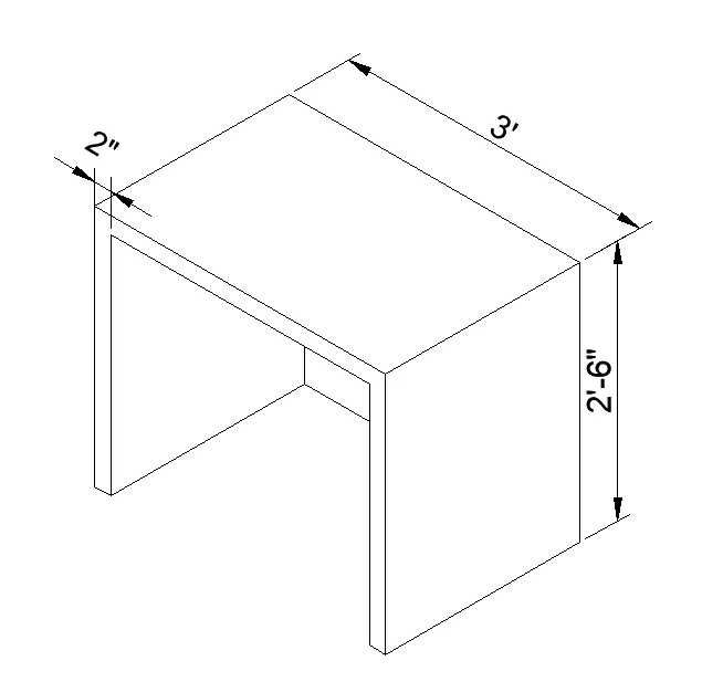
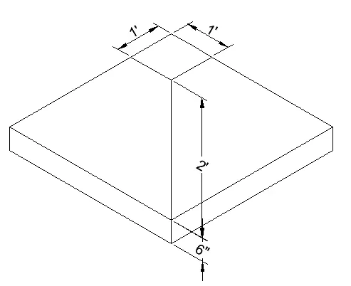
2) AIM: To create the 3d Model of an Isolated footing as shown in Figure.
PROCEDURE:
- Open cad application in the pc and set all the limits required.
- Set the units as required for drawing. Set units in Engineering and scale in Inches.
- Now here we have to change the model space from Drafting to 3D modeling.
- Once you go for 3d modeling a new axis will appear in the UCS icon.
- Here in that new axis 'Z' the all the thickness of extrude goes.
- This is done quite differently. Draw the rectangle in the XYplane.
- Extrude for the thickness of 6inches.
- Then draw the upper rectangle of given dimensions. Then move it in z direction as mentioned.
- Now use command LOFT and it says to select the first point or object.
- Next select the rectangle that is moved up. A sloped footing will appear.
- Go to shade visual style then a 3D model is shown.
- Go to wireframe and do the dimensioning. Then use oblique to make it proper.
RESULT:
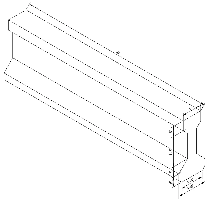
3) AIM: To create the 3D view of the AASTHO Type Girder.
PROCEDURE:
- Open cad application in the pc and set all the limits required.
- Set the units as required for drawing. Set units in Engineering and scale in Inches.
- Now here we have to change the model space from Drafting to 3D modeling.
- Once you go for 3d modeling a new axis will appear in the UCS icon.
- Here in that new axis 'Z' the all the thickness of extrude goes.
- Here first go to UCS option and change the XYplane.
- Because we have to do the sketching in the XY Plane.
- Do the sketching as given dimensions. The there is a region to make a chamfer.
- Go to chamfer and select the distance and type the distance.
- Now select the lines that to be chamfered.
- Continue the drawing and after completing make the REGION of the surface.
- To make the region type R and select the object.
- Once the surface is converted to region now use EXTRUDE command.
- Select extrude and select the direction it goes in Z Axis.
- Then go to shaded or realistic visual and check the figure.
- Then come back to 2D visual and do all the required dimensioning.
- Go to dimension style and change primary units to Engineering.
- Make sure the dimensioning is clearly visible.
RESULT:
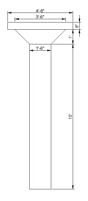
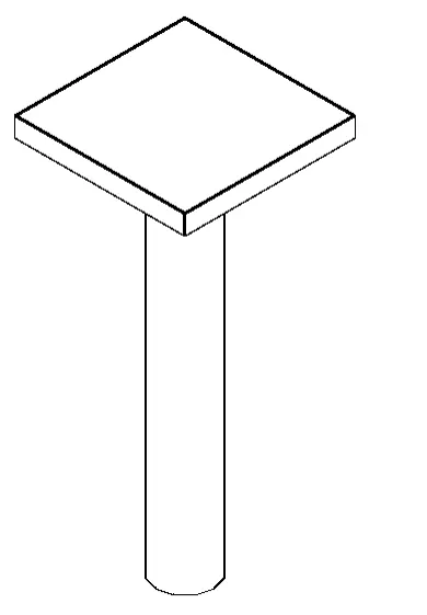
4) AIM: To create a 3d Model of a drop column with panel as shown in section and isometric view.
PROCEDURE:
- Open cad application in the pc and set all the limits required.
- Set the units as required for drawing. Set units in Engineering and scale in Inches.
- Now here we have to change the model space from Drafting to 3D modeling.
- Once you go for 3d modeling a new axis will appear in the UCS icon.
- Here in that new axis 'Z' the all the thickness of extrude goes.
- First draw the circle and the rectangle of top.
- Extrude the circle to mentioned height.
- Move the rectangle in mentioned height.
- Go to solids and select the LOFT the select the circle and the rectangle.
- A sloped cap is obtained then make a rectangle with the given cap size.
- Use extrude to show the thickness.
- Once the drawing is completed then go to shade visual and check the drawing.
RESULT:
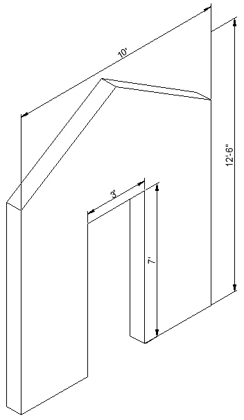
5) AIM: To create the 3d model of a wall as shown in Figure.
PROCEDURE:
- Open cad application in the pc and set all the limits required.
- Set the units as required for drawing. Set units in Engineering and scale in Inches.
- Now here we have to change the model space from Drafting to 3D modeling.
- Once you go for 3d modeling a new axis will appear in the UCS icon.
- Here in that new axis 'Z' the all the thickness of extrude goes.
- Using the co-ordinate method draw the face of the wall.
- Select the line command and using co-ordinate method draw the lines.
- Next change the UCS as the extrude is only done in the Z AXIS.
- Select the new base point and select the x plane and rotate by giving the angle.
- Then give the extrude and select the object then we can either show a path or direction.
- Type the thickness and go for shaded or realistic visual and check.
- Come back to 2D frame and do all the dimensioning.
- Be aware that the dimensions are clearly visible.
RESULT: