Creating various 3D Models like Furniture, Footing, Girder, Column drop with panel and Gable Wall in AutoCad
1Q]
AIM: -
Create a 3D furniture element as shown in Figure.
PROCEDURE: -
Start the AutoCAD with units as IMPERIAL
Set the Units to ENGINEERING
In RIBBON, got to VIEW palette.
In VIEW, go to Viewport tools and turn on the UCS icon, NAVIGATION bar, and VIEW CUBE
Switch the Workspace to 3D MODELLING
Type LINE
Specify First point: 0,0,0
Specify next point: @0’, -2”,0
Specify next point: @0’,0’, 2’6”
Specify next point: @0’,3’,0
Specify next point: @0’,0’, -2’6”
Specify next point: @0’,-2”,0
Specify next point: @0’,0, 2’4”
Specify next point: @0’,-2’8”,0
Specify next point: close
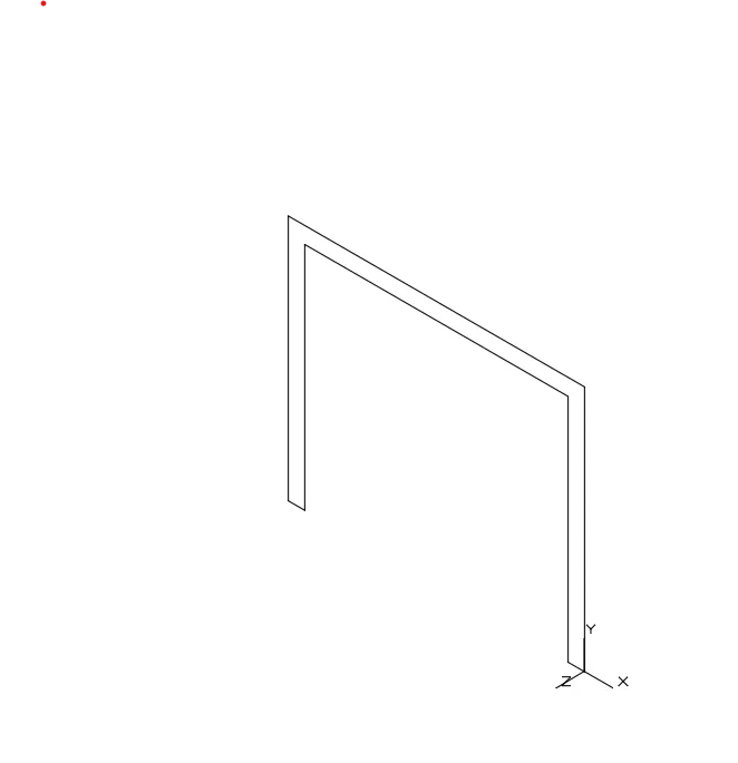
Type REGION
Select all the lines.
Press ENTER.
Set the Visual style to 2D WIREFRAME
Type EXTRUDE
Select the object
Extrude in X-axis of distance 3’ units.
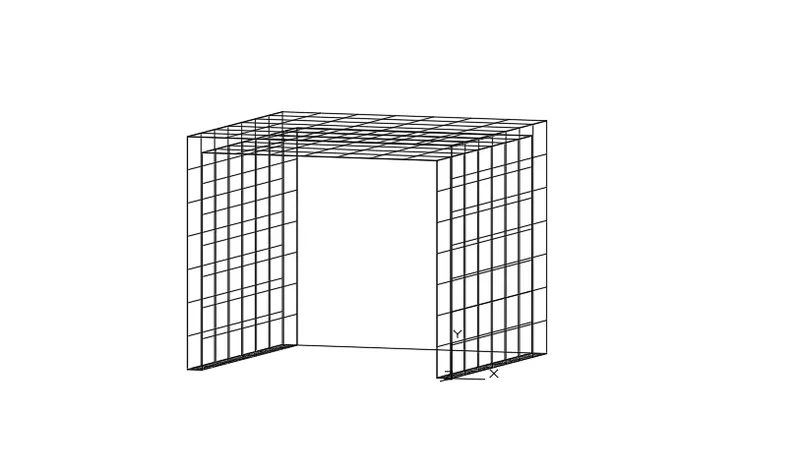
Set the Visual style to 2D WIREFRAME
Set the VIEW CONTROL from SW Isometric to NE Isometric
Type 3DFACE
Select Four corners of the object to close at one side.
Set the Visual style to HIDDEN
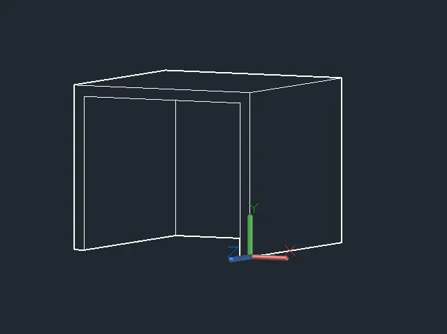
RESULT: -
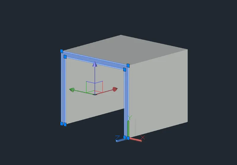
We created the Furniture in the 3D Modelling using Relative Co-ordinate System to locate the points and using 3D modelling commands.
2Q]
AIM: -
Create 3D model of Isolated Footing.
PROCEDURE: -
Start the AutoCAD with units as IMPERIAL
Set the Units to ENGINEERING
In RIBBON, got to VIEW palette.
In VIEW, go to Viewport tools and turn on the UCS icon, NAVIGATION bar, and VIEW CUBE
Switch the Workspace to 3D MODELLING
Set the VIEW CONTROL to TOP
Type RECTANG
Draw Rectangle with Dimensions 1’ x 1’ units.
Press Enter
Set the VIEW CONTROL to SW ISOMETRIC
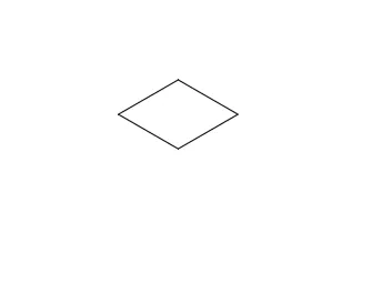
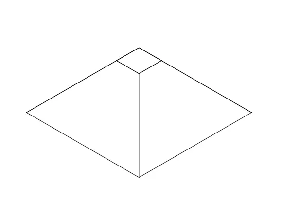
Type EXTRUDE
Select object and press ENTER
Select Taper Angle
Specify Angle of Taper for Extrusion: -45 degrees
Specify height for Extrusion: 2’ units
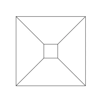
Set the VIEW CONTROL to BOTTOM
Type RECTANG
Draw Rectangle over the bigger Rectangle.
Set the VIEW CONTROL to SW ISOMETRIC
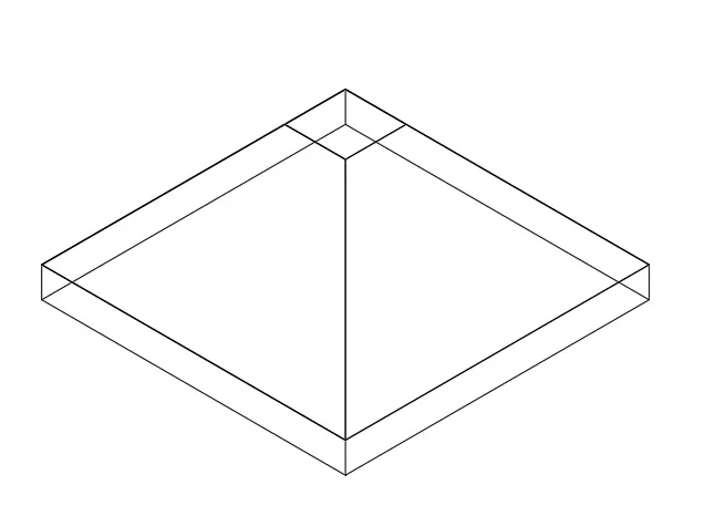
Select the Rectangle drawn.
Type EXTRUDE
Select object and press ENTER
Specify height for Extrusion: 6” units
Press Enter
Type 3DFACE
Select Four corners of the object. (rectangle 1’ x 1’)
Press ENTER
Type HIDE and press ENTER

Set the Visual style to HIDDEN
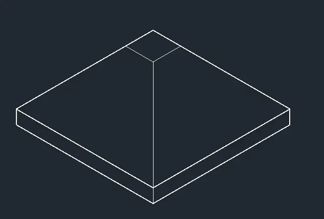
RESULT: -
We ceated the Isolated Footing in 3D modelling.
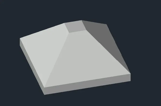
3Q]
AIM: -
Create 3D view of AASTHO TYPE GIRDER
PROCEDURE: -
Start the AutoCAD with units as IMPERIAL
Set the Units to ENGINEERING
In RIBBON, got to VIEW palette.
In VIEW, go to Viewport tools and turn on the UCS icon, NAVIGATION bar, and VIEW CUBE
Switch the Workspace to 3D MODELLING
Set the VIEW CONTROL to TOP
Type LINE
Specify 1st point: 0,0
Specify next point: @0,8”
Specify next point: @6”,0
Specify next point: @8.5” <-45
Specify next point: @1’3”,0
Specify next point: @4.2” <45
Specify next point: @6”,0
Specify next point: @0,6”
Type CHAMFER
Provide chamfer of size 1” x 1” units at longer side of the Girder section.
Type MIRROR
Select the objects and select the mirror line as Horizontal line passing through X axis
Draw the Girder as given in the Figure with dimensions.
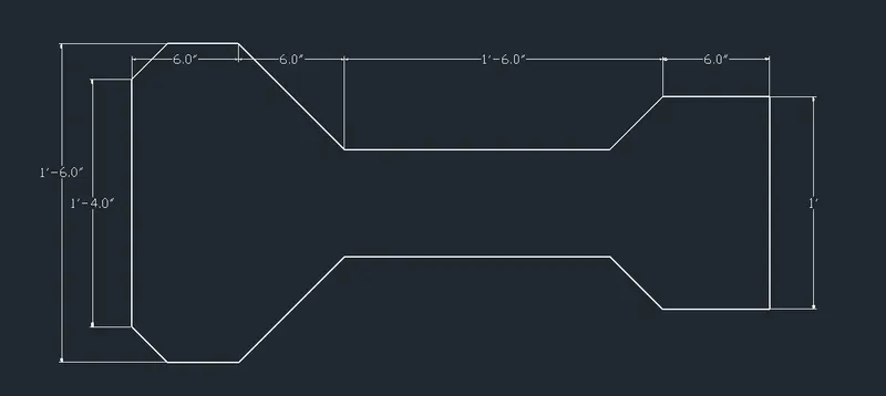
Set the VIEW CONTROL to SW ISOMETRIC
Type REGION
Select all the lines.
Press ENTER.
Type LINE
Draw a line of Length 10’ units along Z axis
Type SWEEP
Select the object as GIRDER
Select the path as Line of 10’ units.
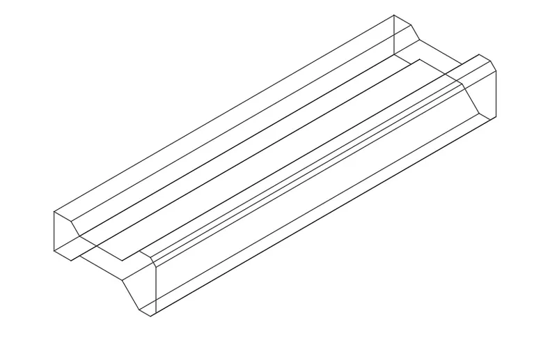
Type ROTATE3D
Select the GIRDER as the object
Select the 2P option and choose the 2 points along the longer side of the girder in Z axis.
Provide rotation angle as 180 degrees
Press ENTER
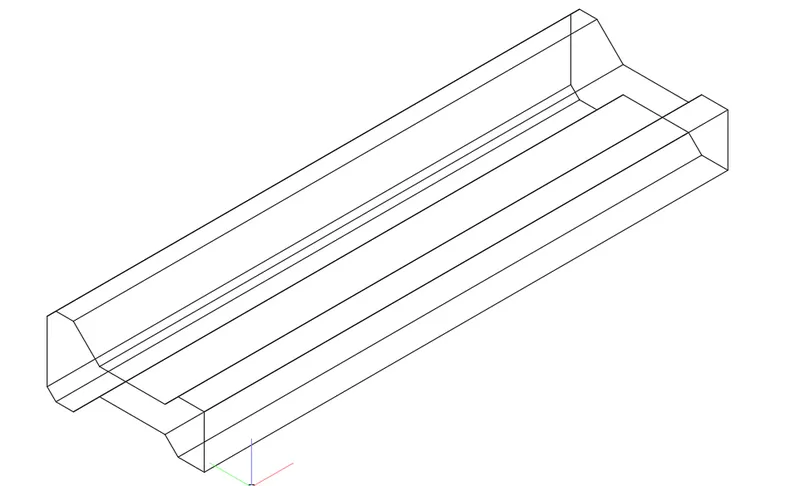
Type 3DFACE
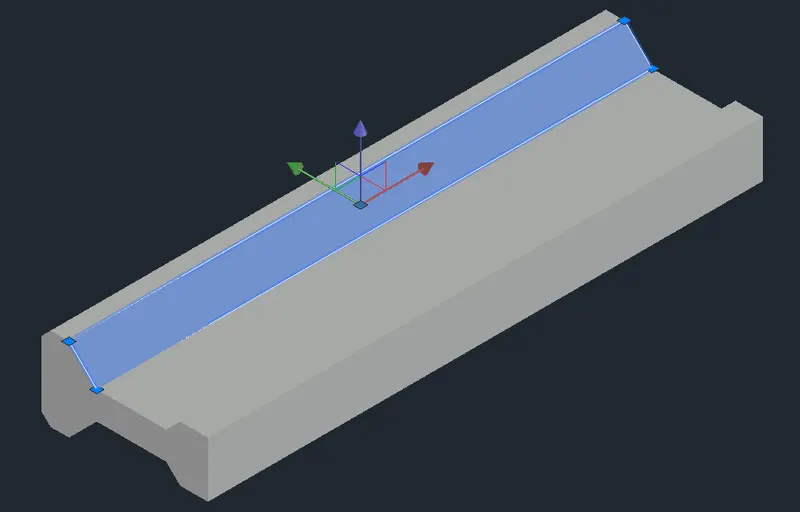
Select Four corners of the object on of the face.
Press ENTER
Type HIDE and press ENTER
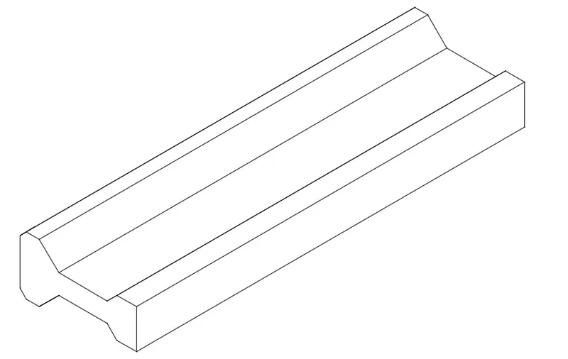
Set the Visual style to HIDDEN
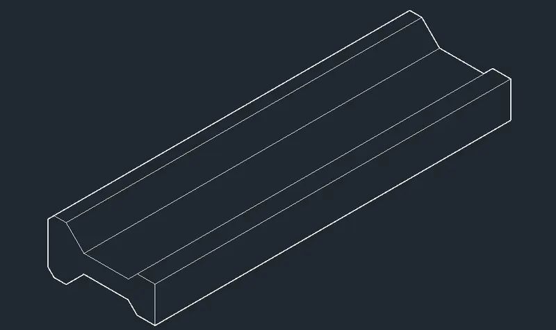
RESULT: -
We created 3D view model of AASTHO TYPE GIRDER
4Q]
AIM: -
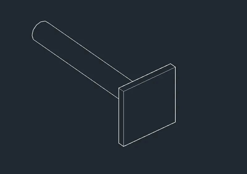
Create a 3D model of Drop Column with panel
PROCEDURE: -
Start the AutoCAD with units as IMPERIAL
Set the Units to ENGINEERING
In RIBBON, got to VIEW palette.
In VIEW, go to Viewport tools and turn on the UCS icon, NAVIGATION bar, and VIEW CUBE
Switch the Workspace to 3D MODELLING
Set the VIEW CONTROL to TOP
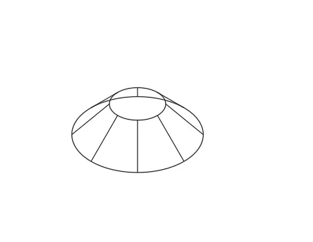
Type CONE
Specify centre point on screen
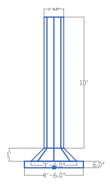
Enter Base Diameter as 3’6” units.
Select Top radius option as Enter the radius value as 9”
Specify Height as 1’ units.
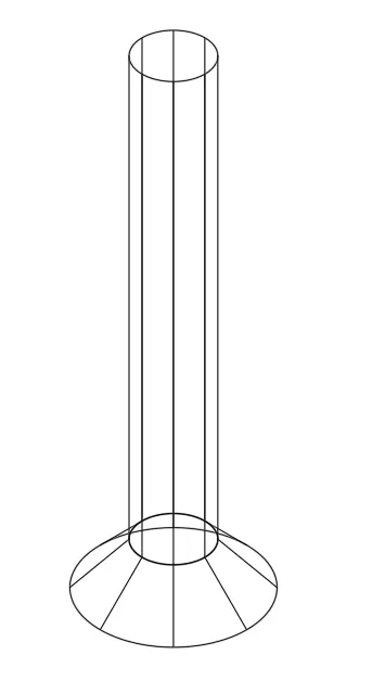
Type CYLINDER
Specify Centre point as Cone centre point
Specify base radius as 9” units.
Specify Height as 10’ units.
Type RECTANG
Draw Rectangle with Dimensions 4’6” x 4’6” units.
Press ENTER
Set the VIEW CONTROL to BOTTOM
Type MOVE
Select the object as Rectangle.
Select the base point as geometric centre of the Rectangle.
Move the Rectangle and match to the Geometric centre bigger circle of the cone.
Press ENTER
Set the VIEW CONTROL to SW ISOMETRIC
Type Extrude
Select Rectangle as object
Specify Height as 1’ units
Press ENTER
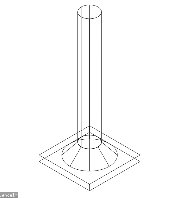
Type UNION
Select the 3 objects- Cube, Cone, Sphere
Press Enter
Now the 3 objects unite and becomes single Entity
Type ROTATE3D
Select the object
Specify the rotation axis as X-axis.
Specify the rotation angle as 90 degrees
Press ENTER
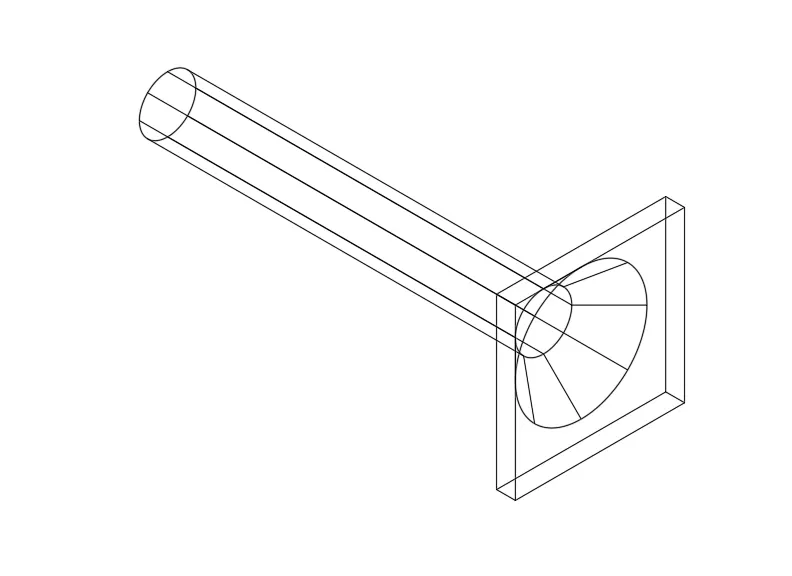
Type FACE3D
Select the 4 points of SQUARE corners
Press ENTER
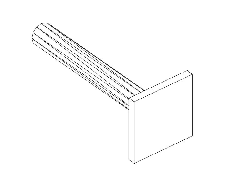
Type HIDE and press ENTER
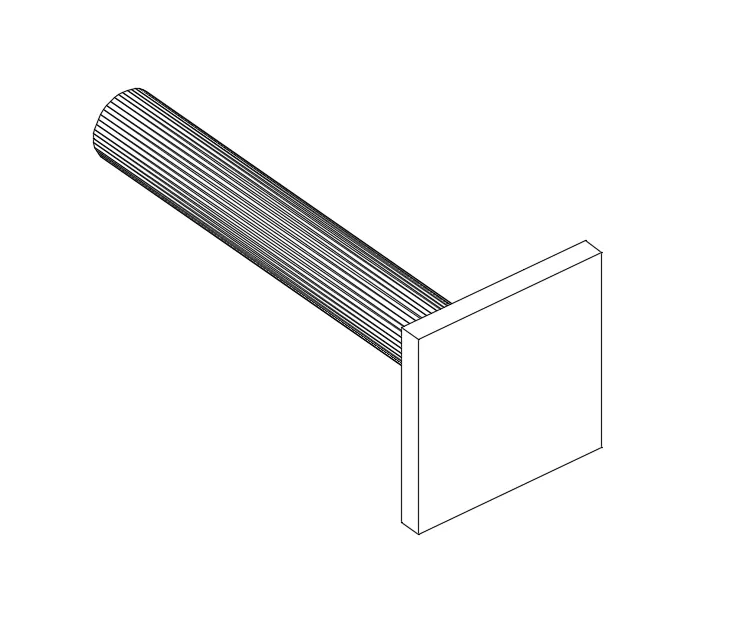
Type FACETRES
Enter the value as 10
Press ENTER
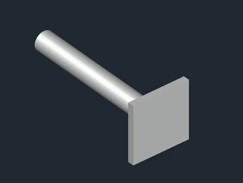
RESULT: -
We created the 3D view of Drop Column with Panel.
5Q]
AIM: -
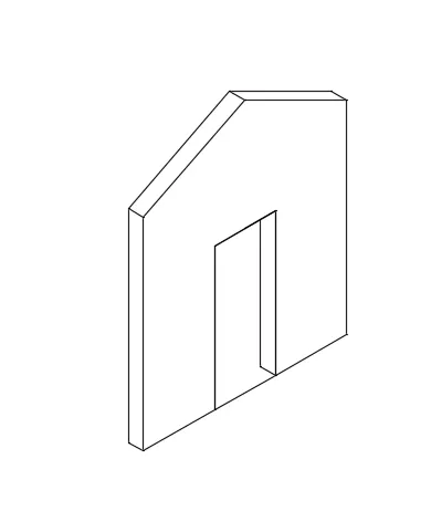
Create the 3D model of a WALL
PROCEDURE: -
Start the AutoCAD with units as IMPERIAL
Set the Units to ENGINEERING
In RIBBON, got to VIEW palette.
In VIEW, go to Viewport tools and turn on the UCS icon, NAVIGATION bar, and VIEW CUBE
Switch the Workspace to 3D MODELLING
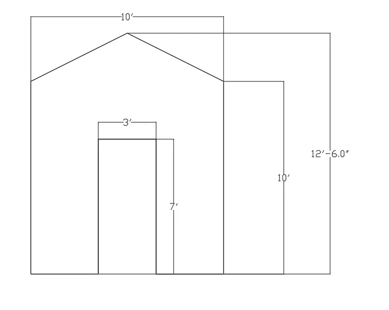
Set the VIEW CONTROL to FRONT
Type LINE
Specify 1st point: 0,0
Specify next point: @0,10’
Specify next point: @5’,2’6”
Specify next point: @5’, -2’6”
Specify next point: @0, -10’
Specify next point: @-3’,0
Specify next point: @0,7’
Specify next point: -3’,0
Specify next point: 0, -7’
Specify next point: close
Set the VIEW CONTROL to SW ISOMETRIC
Type JOIN
Select the lines of the walls.
Press ENTER
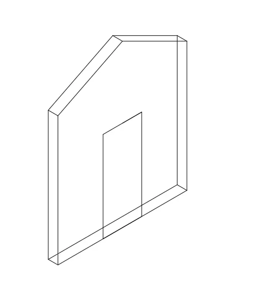
Type EXTRUDE
Select the wall
Specify height for Extrusion: 9” units
Press ENTER
Type JOIN
Select the lines of the Door.
Press ENTER
Type REGION
Select the lines of the walls.
Press ENTER
Type EXTRUDE
Select the DOOR
Specify height for Extrusion: 9” units
Press ENTER
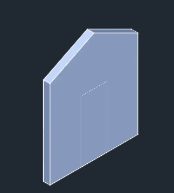
Type SUBTRACT
Select the wall and press Enter
Select the Door and press Enter
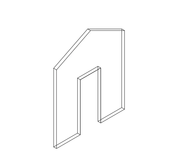
Type HIDE and press ENTER
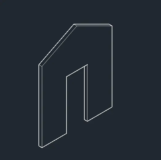
RESULT: -
We created the 3D model of the WALL with Door