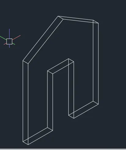
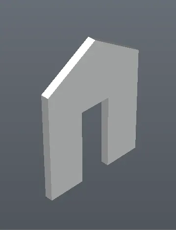
Creating various 3D Models like Furniture, Footing, Girder, Column drop with panel and Gable Wall in AutoCad
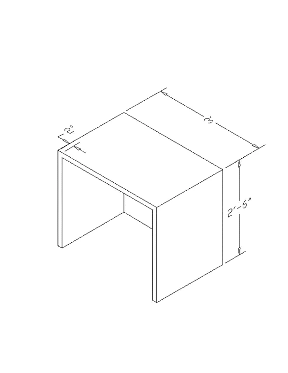
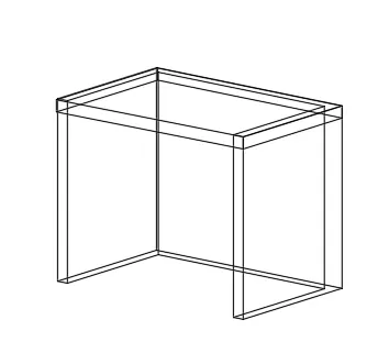
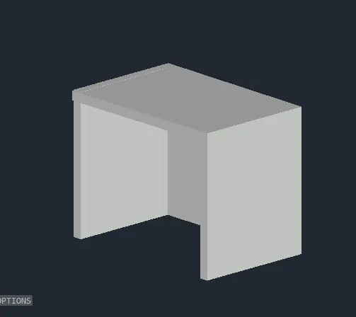
1. Create a 3D Furniture element as shown in the Figure. Assume dimensions which are missing.
AIM:
To create a 3D furniture element as given in the figure and need to assume dimensions which are missing in the drawing.
INTRODUCTION:
The three-dimensional furniture element was drawn in the AutoCAD using the different tools in the AutoCAD
3D models are widely used anywhere in 3D graphics and CAD
Their use predates the widespread use of 30 graphics on personal computers the 3d models are mainly preferable in civil engineering and when we design a building in the AutoCAD then creating 3d models
PROCEDURE:
Open the AutoCAD
Type UN in the command prompt
Select the Engineering and precision to 0'0"
Select the 3D modelling
Type 2'6" in the command prompt X-axis keeping the mouse in the X-direction
Type 2'6" in the command prompt Z-axis keeping the mouse in the Z-direction
Type 3' in the command prompt Y-axis keeping the mouse in the Y-direction
Type 2'6" in the command prompt on the X-axis keeping the mouse in the direction
Type 2'6" in the command prompt Z-axis keeping the mouse in the direction
Type offset and specify the distance as 2" and do the offset of the Z-axis
Change the plane and do the offset of 2" and do the offset on Y-axis
Join the line wherever required
Using the 3DF command to form the 3D faces
Using the HIDE command, hide the background lines
The desired drawing is obtained
RESULT:
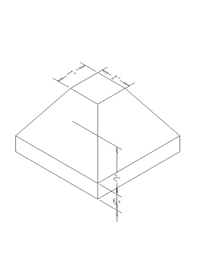
2. Create the 3d Model of an isolated footing as shown in Figure.
AIM:
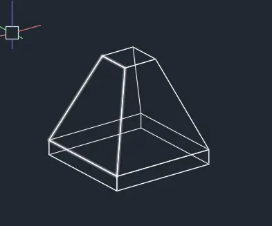
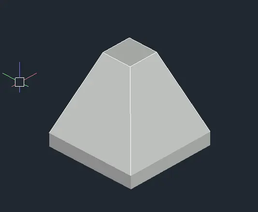
To draw the 3d wireframe model of an isolated footing as shown figure by using the AutoCAD tool
INTRODUCTION:
The 3d model given is an isolated footing. This 3d model is of trapezoidal tapered isolated footing.
An isolated footing is used to support a single column.
Isolated footings are independent footings which are provided for each column.
Its simplicity and economic nature make it the most commonly used reinforcement footing.
PROCEDURE:
Set the units using the UN command.
Select the DIMSTYLE command and select primary units as architectural.
Use the UCS command to set the directions of the x-axis, y-axis and z-axis.
Draw the rectangle using the line command with the size of 3x3
Use EXTRUDE command to extrude the rectangle upwards with the length of 6”
Draw another rectangle at the centre of the outer rectangle
Move the inner rectangle upwards by a distance of 2’
Using the 3DF command to form the 3D faces
Using the HIDE command, hide the background lines
RESULT
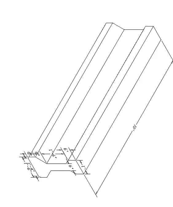
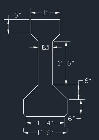
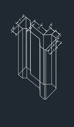
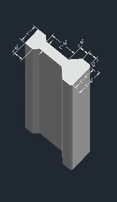
3. Create the 3D view of the AASTHO Type Girder.
AIM:
To draw the 3D wireframe model of an AASTHO type girder as shown figure by using the AutoCAD tool
PROCEDURE:
Type UN in the command prompt and select ENGINEERING and precision to 0'-0"
Enter the LINE command and type 1'4" in the x-direction
Type @1"<45
Type @6"<90
Type @8"<135
Type @1'6" <90
Type @4"<45
Type @6”<90
Select all the lines and mirror it using the MIRROR command
Join the line
Type BO in the command prompt and region the object
Select the EXTRUDE command and pull it 10’
RESULT:
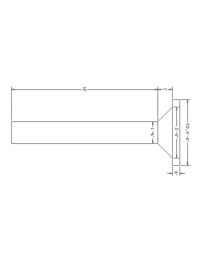
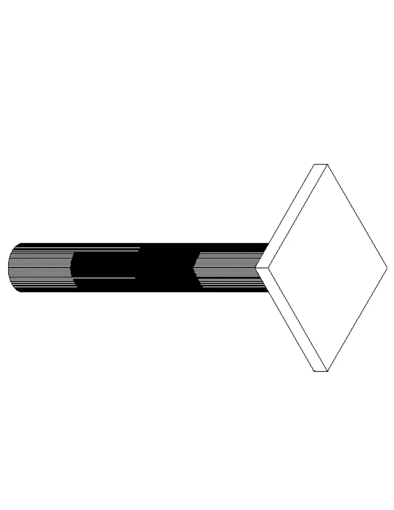
4. Create a 3d Model of a drop column with the panel as shown in the section and isometric view.
AIM:
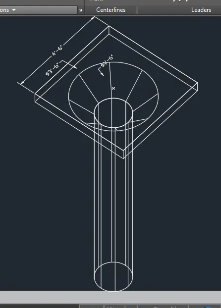
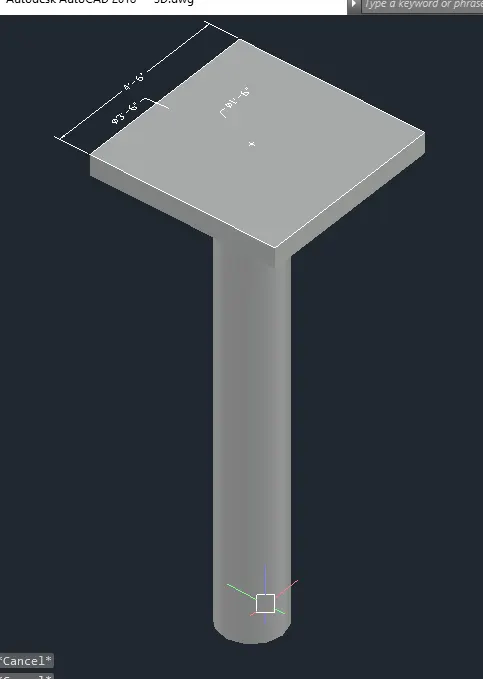
To draw the 3D wireframe model of a drop column as shown figure by using the AutoCAD tool
INTRODUCTION:
The 3D model given is a drop column used for the construction of flat slabs. A drop column is used when a beam is not required in the design. Drop is a part of the slab around the column, which has a greater thickness than the rest of the slab. The drop column not only eliminates the need for a beam but also gives a plain ceiling and great appetence, better light diffusion, and more open rooms.
A flat slab is designed by two methods
- Direct design method.
2. Equivalent frame method
PROCEDURE:
Type UN in the command prompt and select ENGINEERING and precision to 0'-0"
Draw a square of side 4’6”
Create the surface using the 3DF command
Extrude the surface by 6”
Draw a circle of diameter 3’6”
Create the surface using the 3DF command
Extrude the surface by 12” with a tapered angle of 45
Draw another circle of diameter 1’6”
Create the surface using the 3DF command
Extrude the surface by 10’
RESULT
5. Create the 3d model of a wall as shown in Figure. Consider wall thickness as 9”.
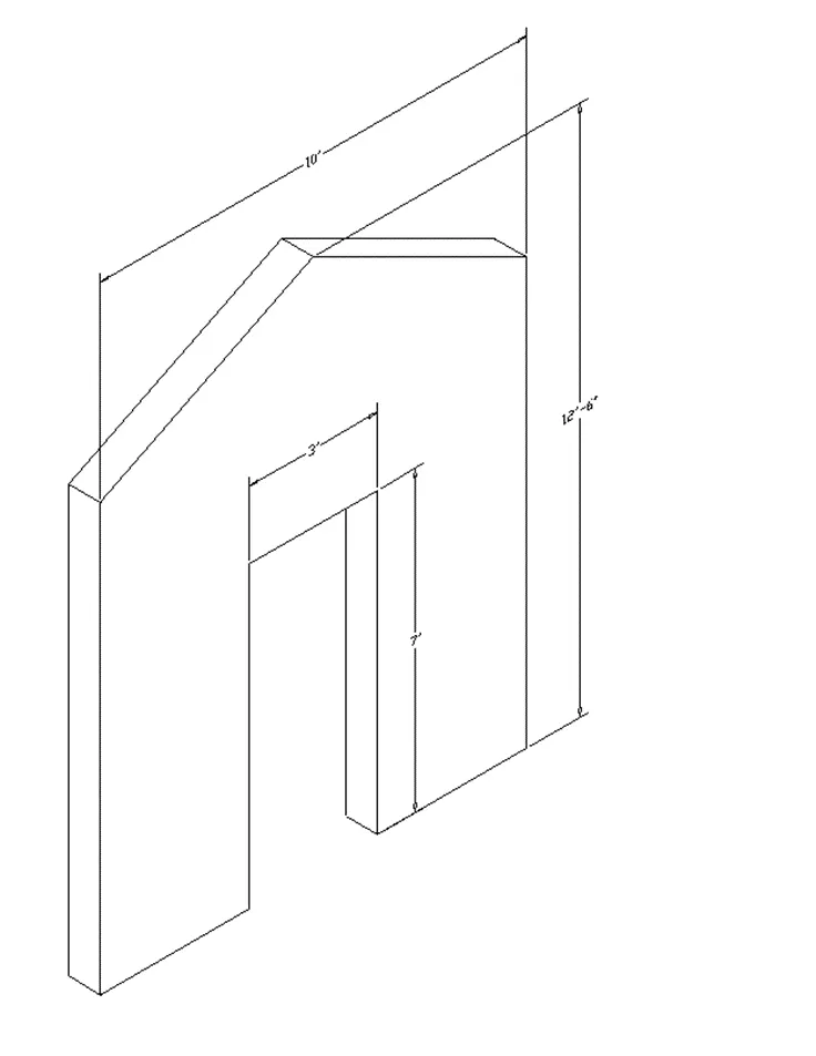
PROCEDURE:
Enter the LINE command
Draw a line of 3.5’ in X-direction
Move the cursor up and draw a line of 7’
Move the cursor right and draw a line of 3’
Move cursor down and type 7’
Move the cursor right and type 3.5’
Move the cursor up and type 10’
Draw a horizontal line of 10’
Close the figure
From the midpoint of the top horizontal line draw a vertical line of 5’
Join the ends of vertical lines to this line
Erase the extra lines
Join the figure using the JOIN command
Using the REGION command, create the region
Extrude the region by 9” using EXTRUDE
RESULT