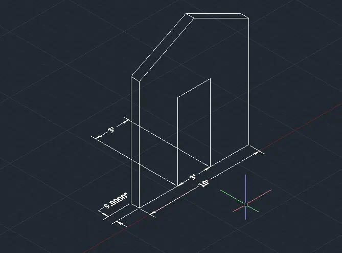
Creating various 3D Models like Furniture, Footing, Girder, Column drop with panel and Gable Wall in AutoCad
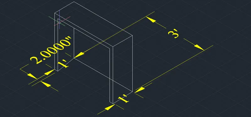
- AIM: To create the a 3d furniture as shown in the figure
- PROCEDURE:
- Type ''un'' and set the units in ''engineering'' and ''inches''
- Select the workspace in '3d modelling'' in the workspace
- Take line command select the first point
- specify the next point >@0,0,2.6''>enter
- specify the next point > @ 0,3',0 enter
- specify the next point > @0,0,-2.6>enter
- specify the next point> @ 0,-2,0 >enter
- specify the next point> @ 0,0,2.8''>enter
- specify the next point> @0,0,-2.4'' >enter
- specify the next point > @0,-2'',0>enter
- Take the rectangle command
- Specify the first corner point >click on the left corner point
- Click>dimension
- Specify the length >2.2''
- Specify the width >3'
- Use line command to connect the rectangle as shown in the figure
- RESULT
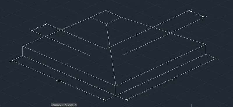
- AIM: To create the 3d model of an isolated footing as shown in the figure
- PROCEDURE:
- Take the rectangle command
- Specify the corner point in the drawing
- Click>dimension
- Specify the length >1'
- Specify the width >1'
- By keeping the object snap on Keep small rectangle such as both rectangle shows the same centre point
- Take the move command Click on the small rectangle
- Mske it in a z axis at a distance of a 2'6
- Take the line command
- Join all the corner point Take 3D face command
- Specify all four point of rectangle
- Enter>hide>enter
- Take the extrude command
- Select the object > Click on the rectangle
- Specify the extrude height >6'
- Change the visual style control>hidden
- Click on annotation tab
- Click on the dimension Click>Manage dimension style
- style name >3d
- Set the characteristics of dimension as
- Provide dimension
- RESULT
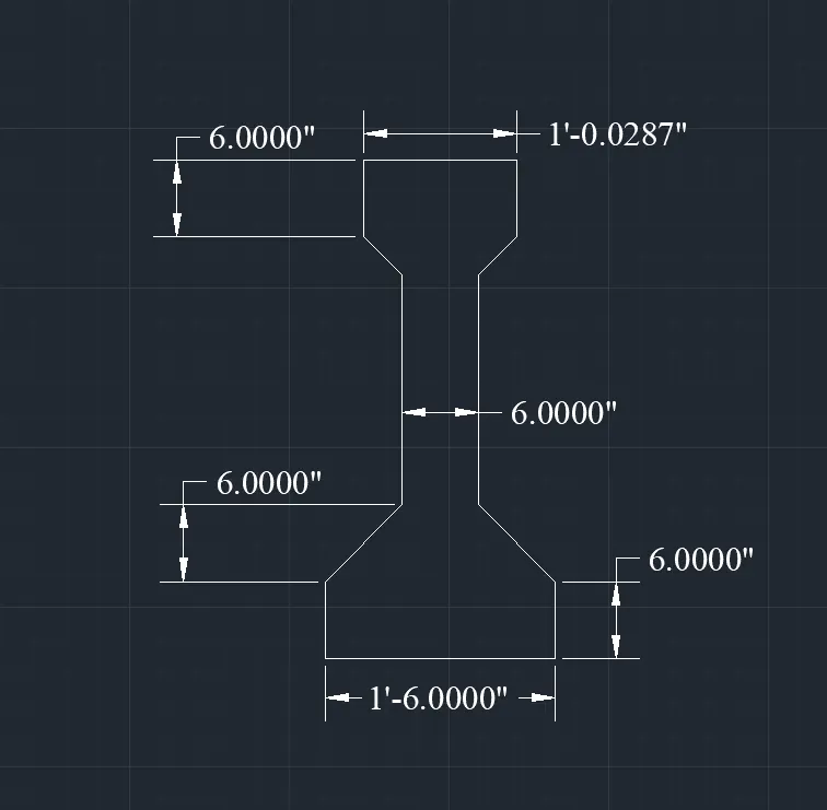
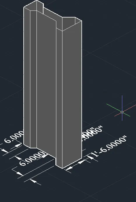
- AIM: To create the 3d view of the aastho type girder as per shown in the figure
- PROCEDURE:
- Select the view > top
- Take the line command
- Select the first point in the drawing
- Specify the next command >1'6
- S[ecify the next point > 6''
- Take the offset command
- Specify the distance as 6''
- Select the object line> Click on the horizontal command
- Take the extrude command
- Select the object >click on the rectangle
- Specify the extrude height>10'
- Change the visual style control> shaded with glass
- RESULT
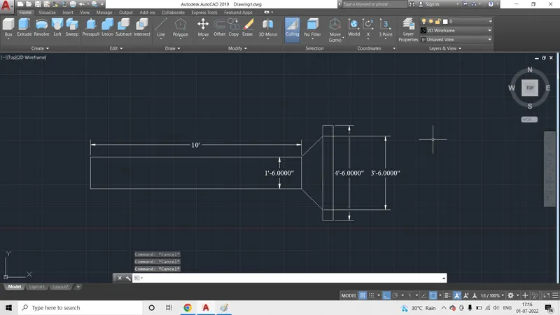
- AIM: To create 3d model of a drop column with panel as shown in the section
- PROCEDURE
- Select the view >topTake the ci
- Take rectangle command
- Select the first corner point in the drawing
- Click dimension and specify the length and width > 4.6''
- Take the circle command Specify centre> anywhere
- Click diameter and specify the diameter >1.6''
- Enter take move command
- Select the object the > click on the smaller circle
- Specify the distanc 1'' and move it along it along z axis
- Take the circle command and specify the centre
- Make it region and extrud the command
- Select the object and click on the latest circle drawn
- Extrude the height 10'
- RESULT
- AIM: To create the 3d model of a wall as shown in the figure
- PROCEDURE
- Take the line command
- Specify the next point >@3.6,0,0
- Specify the next point>@0,0,7
- Specify the next point>@3,0,0
- Specify the next point>@0,0,-7
- Specify the next point>3.6,0,0
- specify the next point>0,0,9
- Specify the next point>-10,0,0
- Specify the next point>0,0,-9
- From bottom midpoint of door draw the line of 12.6'
- RESULT