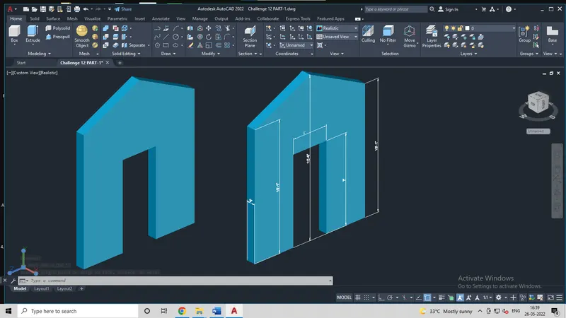
Creating various 3D Models like Furniture, Footing, Girder, Column drop with panel and Gable Wall in AutoCad
Task: 1
Aim: To draw a 3D representation of a furniture element assuming certain dimensions and as per the given details.
Introduction:
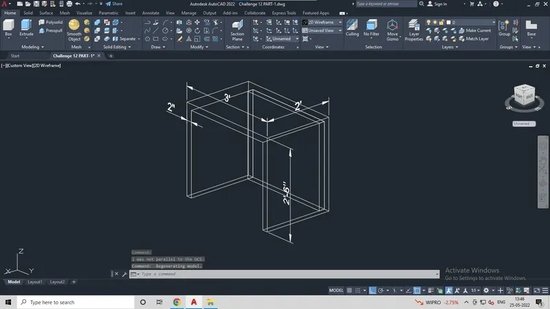
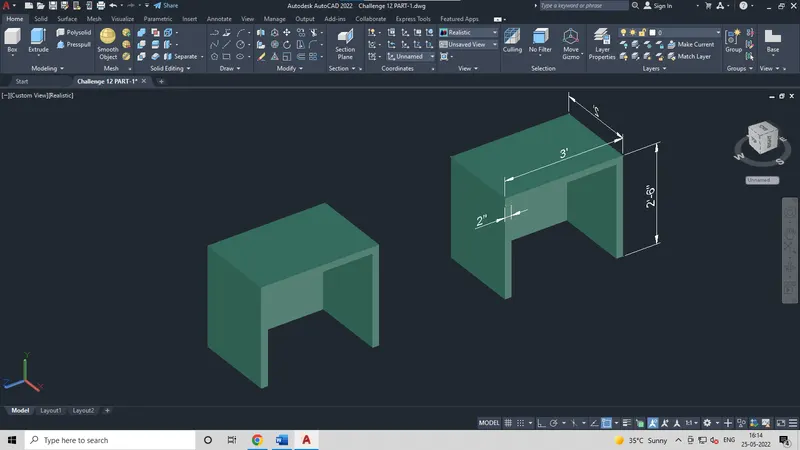
A 3D view of the furniture element is provided with few dimensions like its height which is 2’-6”, its width 3’, its thickness i.e. 2”.
Other details such as it’s depth is to be assumed.
Procedure in Detail: Open AutoCAD, then setup units which is to setup the dimension or measurement format of the particular AutoCAD file with the help of which the dimensions would be measured and represented as given.
Change the workspace settings from drafting to 3D modelling.
Step:1
create layers if needed and work accordingly.
Step:2
Select Polyline and draw a rectangle of dimension 3’ X 2’-6”.
Give Offset command and draw another rectangle at 2” distance towards inside, considering any point at the outer rectangle.
Give indicative dimensions.
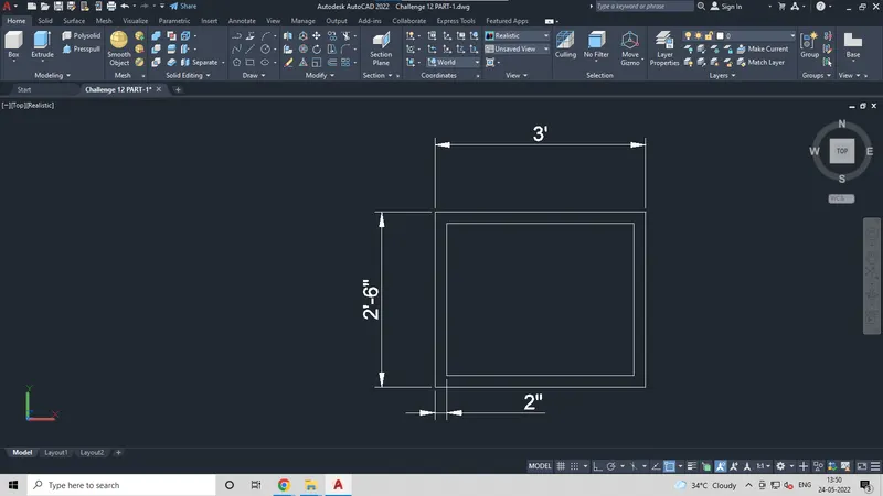
Step:3
After giving indicative dimensions,
Trim the unnecessary lines and join the open left out ones as in figure shown.
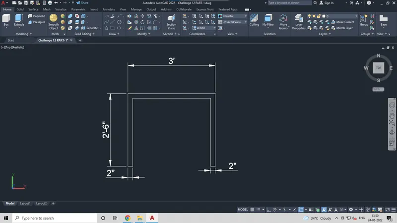
Step:4
Extrude the structure at a height of 2’.
And then rotate it with the help of 3D rotate command at an angle of 90degree.
Use subtract command and subtract the center portion from the outer body.
Adjust the screen to view the structure properly.
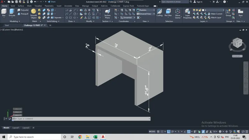
Step:5
Color/ choose layer color for the furniture element according to your choice, which is totally optional.
Result:
Thus, the required 3D model of the furniture element is obtained as below.
Task: 2
Aim: To create the 3D model of an isolated footing as per the provided details.
Introduction:
A 3D view of an isolated footing is provided with few dimensions like its height which is in total 2’-6”, width of the peak part i.e. 1’ X 1’ and other dimensions are to be assumed.
Procedure in Detail: Open AutoCAD, then setup units which is to setup the dimension or measurement format of the particular AutoCAD file with the help of which the dimensions would be measured and represented as given.
Change the workspace settings from drafting to 3D modelling.
Step:1
create layers if needed and work accordingly.
Step:2
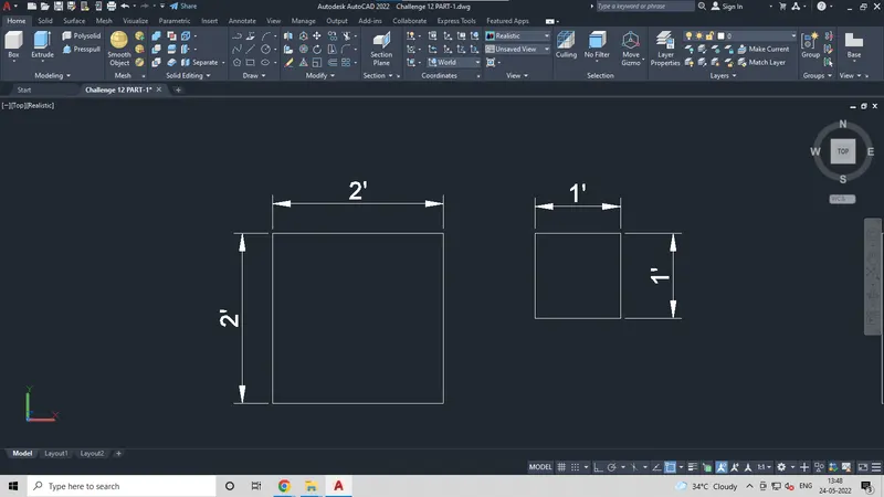
use square command and draw a square of dimension 2’ X 2’.
Take a copy of this square (i.e. 2’ X 2’) on a side which will be used later to form the base of the model.
Again repeat the same and draw a square of 1’ X 1’.
Step:3
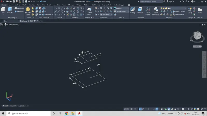
Now place the small square (i.e. 1’ X 1’) over the bigger (i.e. 2’ X 2’) square by matching both the squares center.
Now use move command and shift the small square (i.e. 1’ X 1’) at the height of 2’ from the center of the bigger (i.e. 2’ X 2’) square.
The same is shown in figure below.
Give indicative dimensions.
Step:4
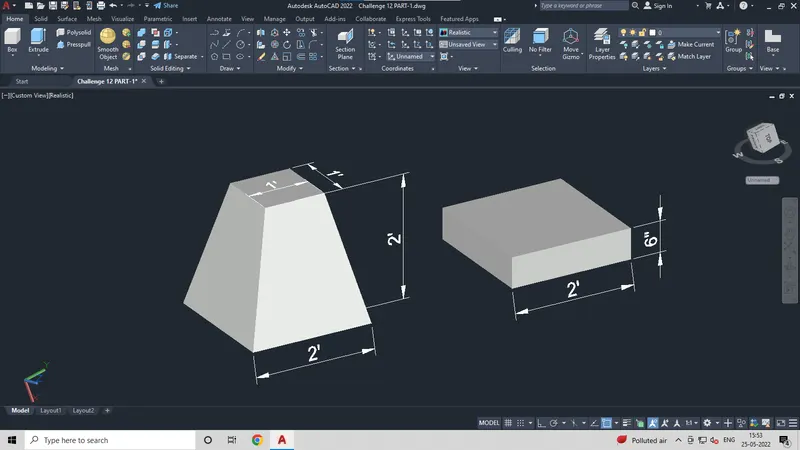
Now use loft command and select the boundary of both the squares.
And a final 3D object will be formed.
Next is to take copied square (i.e. 2’ X 2’), which was kept on a side.
Extrude the same at a height of 6”.
The same is shown in figure below.
Step:5
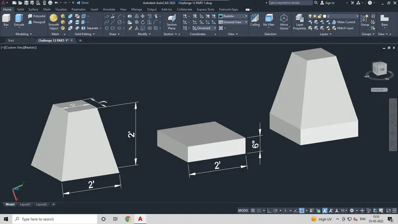
Now combine both the parts together by taking any one point as refrence.
And thus, a complete 3D isolated footing structure will be formed.
Adjust the screen to view the structure properly.
Step:6
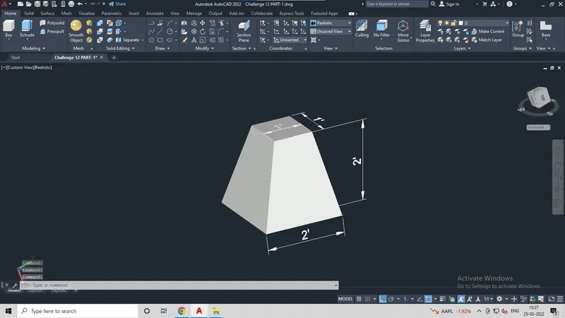
Give indicative dimensions to the whole 3D model.
Color/ choose layer color for the furniture element according to your choice, which is totally optional.
Result:
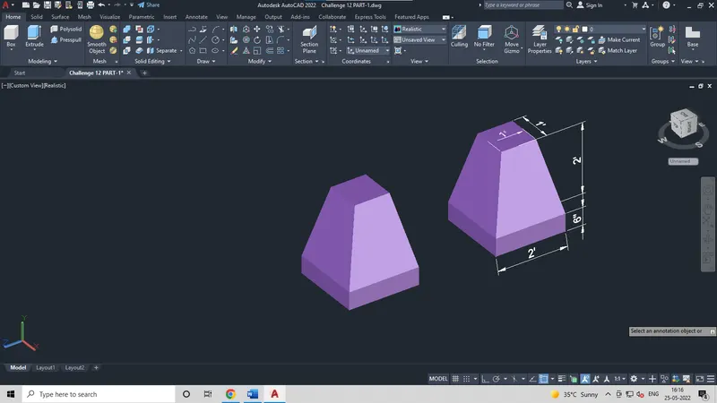
Thus, the needed 3D model of an isolated footing is created as below.
Task: 3
Aim: To create the 3D model of AASTHO type grider with the help of given dimensions and details.
Introduction:
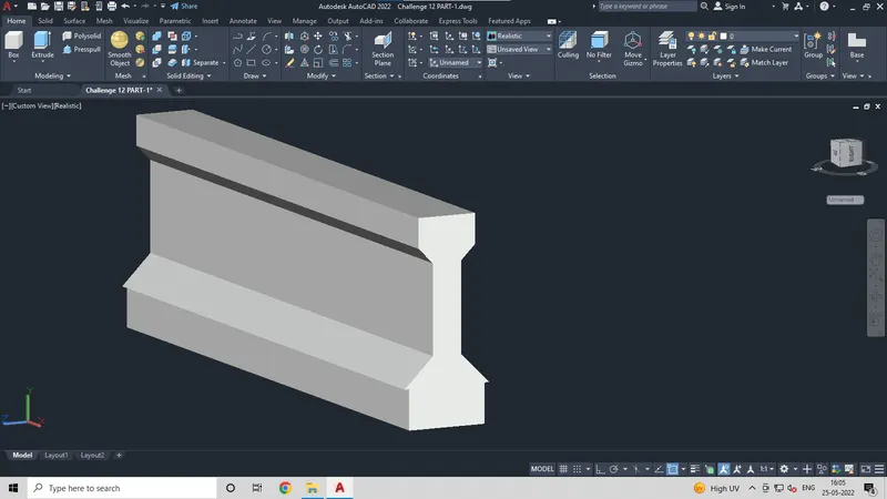
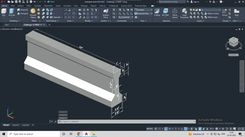
A complete 3D, 2-wired view of an AASTHO type grider is provided with all dimensions required to form it.
Like its height is given in parts, which is a total of 3’, depth of the same is 10’ and other dimensions are to be assumed if required.
Procedure in Detail: Open AutoCAD, then setup units which is to setup the dimension or measurement format of the particular AutoCAD file with the help of which the dimensions would be measured and represented as given.
Change the workspace settings from drafting to 3D modelling.
Step:1
create layers if needed and work accordingly.
Step:2
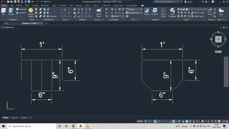
Use rectangle command and draw a rectangle of dimension 1’ X 6”. Select explode command and trim its bottom line (i.e. of 1’).
Draw a polyline of length 9” from the center of the same left-out rectangle.
Now take an Offset at 3” from the center line on both the side towards outside.
Join the rest as shown in figure and trim the unnecessary lines.
Thus a completed shape is formed, which will be the upper portion of the grider.
Step:3
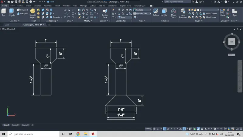
Now draw a rectangle of dimension 6” X 1’-6”.
Draw a Line of 1’ X 6” and place it at the bottom of the rectangle (i.e. 6” X 1’-6”) by matching center of both the things.
Then move the line at a distance of 6” taking center of line as reference.
Join the rest as shown in figure.
Draw a rectangle of 6” X 1’-4” and place the same in the center of the previous structure.
Thus, an overall 2D view of the structure will be formed.
Give indicative dimensions.
Step:4
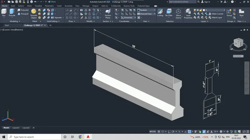
Now select the whole 2D structure and rotate it at an angle and adjust the screen for better visual.
Extrude the 2D structure at a depth of 10’.
And a final 3D object will be formed.
The same is shown in figure below.
Step:5
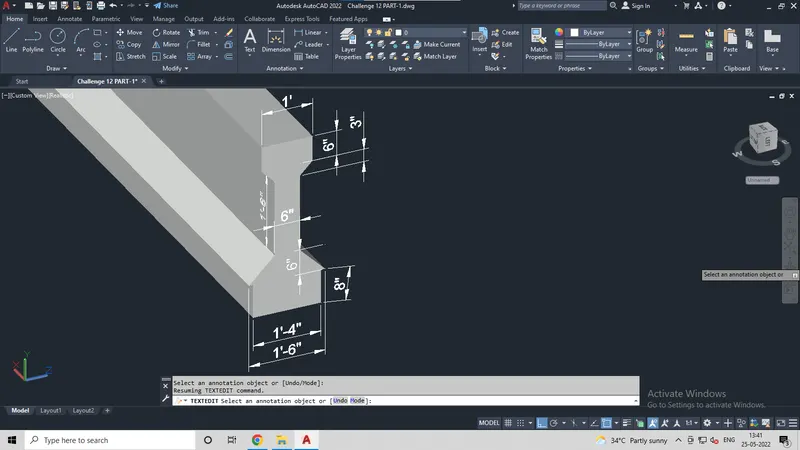
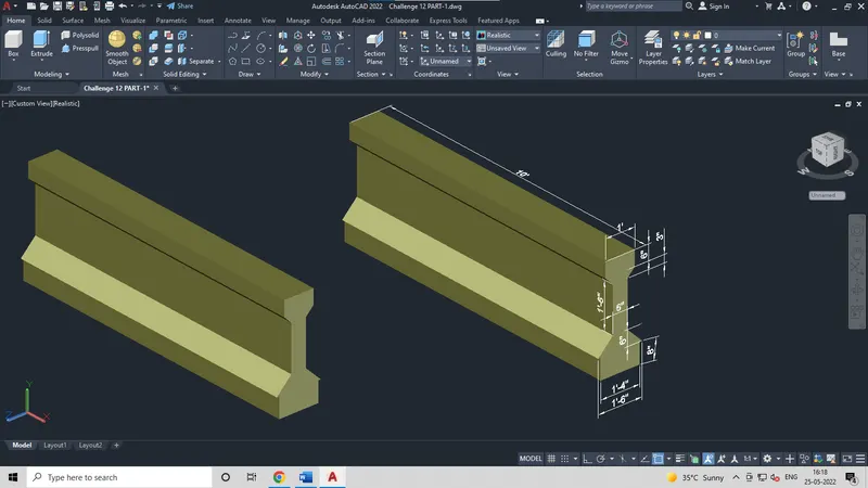
Give detail indicative dimensions to the 3D model.
Step:6
Color/ choose layer color for the furniture element according to your choice, which is totally optional.
Result:
Thus, exactly the same 3D model of an of AASTHO type grider is created as represented below.
Task: 4
Aim: To create a 3D model of a drop column with panel with the help of isometric view and sections provided.
Introduction:
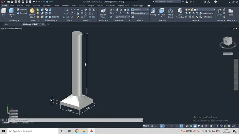
To create a drop column and its panel with the given specifications specifically dimensions like height of the column = 10', diameter of the base 1'-6", width 3'-6", height = 6" of the base and other details.
Procedure in Detail: Open AutoCAD, then setup units which is to setup the dimension or measurement format of the particular AutoCAD file with the help of which the dimensions would be measured and represented as given.
Change the workspace settings from drafting to 3D modelling.
Step:1
create layers if needed and work accordingly.
Step:2
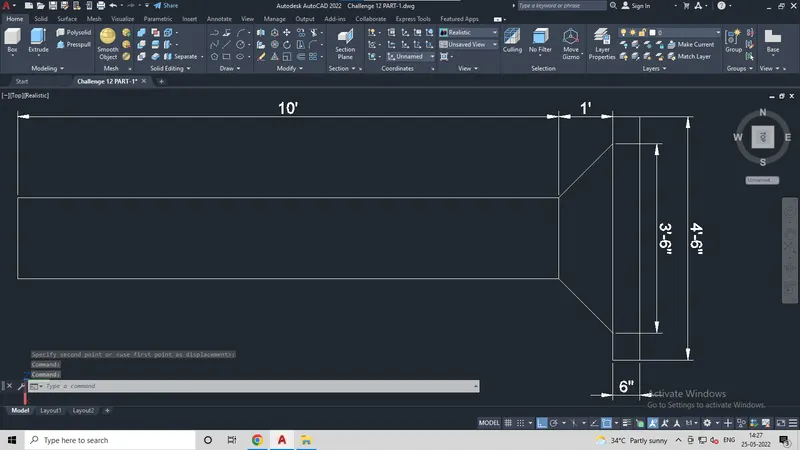
Use rectangle command and draw a rectangle of dimension 10’ X 1’- 6”.
Draw another rectangle of dimension 4’-6” X 6” (Should be at 90 degree from the prev. rectangle)
Now take the rectangle of dimension 4’-6” X 6” & place it near the previous rectangle (i.e., 10’ X 1’- 6”) by matching center point of both the rectangles.
Now move the rectangle (which is 4’-6” X 6”) from the bigger rectangle at an offset of 1’.
Join the rest as shown in figure.
Thus a complete 2D shape of drop column is formed.
Step:3
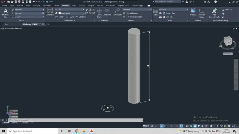
Now draw a circle of diameter 1’-6”.
Use extrude command and extrude the circle to the height of 10’, which will give a cylindrical model at the end.
Step:4
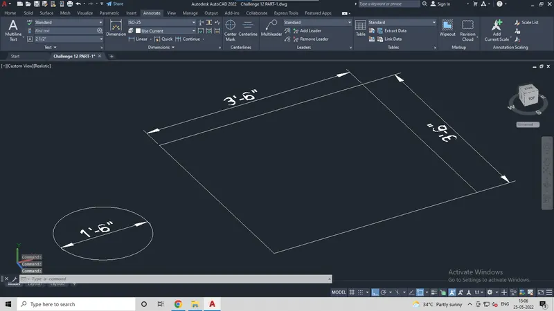
Draw another square of dimension 3’-6” X 3’-6”, with the help of square command. (Copy the same for further steps, where the same can be used.)
Move the circle (D = 1’-6”) over the square (L = 3’-6” X 3’-6”) by matching center of both the objects.
Step:5
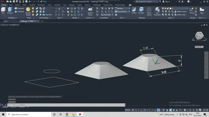
Then move the circle taking the center as reference to a height of 1’.
A 2D view of the same is shown in figure.
Use Loft command select both the objects and a 3D model of an object will be formed.
Which is also represented in the below figure.
Give indicative dimensions.
Step:6
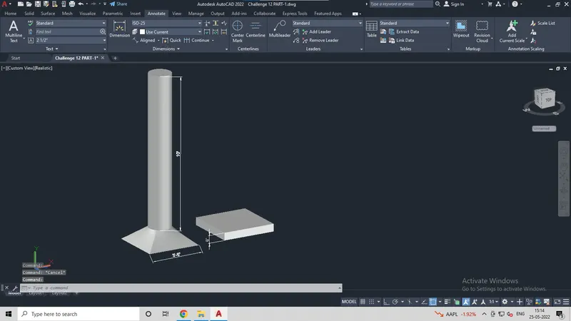
Now move the cylindrical structure over the triangle sort of structure (which is obtained after using loft command) by matching the center’s of both the objects.
The copy of square (3’-6” X 3’-6”) will be helpful now as you need to extrude the boundary to a height of 6”.
Step:7
Combine, all the three objects which will give us the final 3D object.
The same is shown in figure below.
Step:8
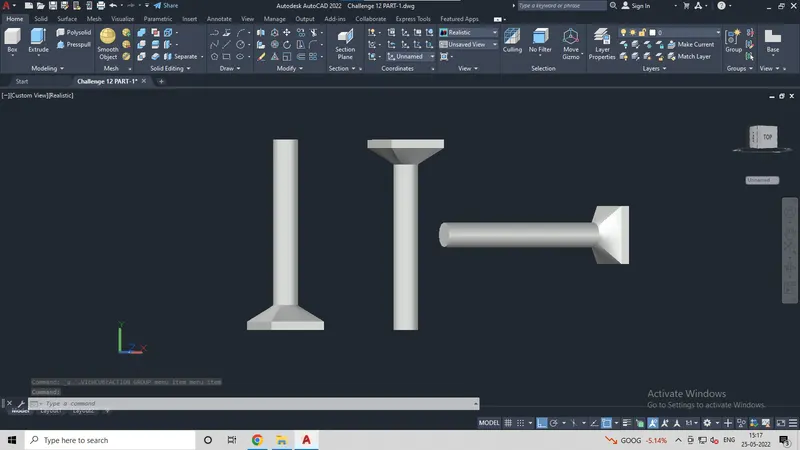
Give detail indicative dimensions to the 3D model.
Also rotate it at different angles to get the idea of its view from every side.
Step:9
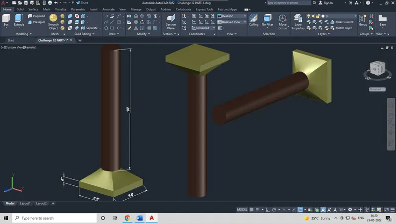
Color/ choose layer color for the furniture element according to your choice, which is totally optional.
Result:
Thus, the asked 3D model of an drop column with panel is created and visually represented below.
Task: 5
Aim: To create a 3D model of a wall considering thickness of 9” as provided.
Introduction:
A complete 3D view of wall column is provided with few dimensions and the rest is to be assumed as required.
Like the angle at which the peak of the house is to be drawn.
Procedure in Detail: Open AutoCAD, then setup units which is to setup the dimension or measurement format of the particular AutoCAD file with the help of which the dimensions would be measured and represented as given.
Change the workspace settings from drafting to 3D modelling.
Step:1
create layers if needed and work accordingly.
Step:2
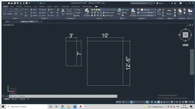
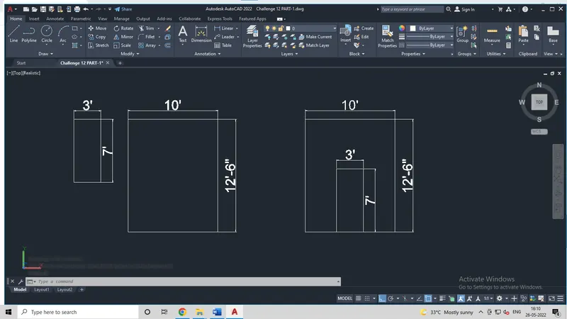
Use rectangle command and draw a rectangle of dimension 10’ X 12’- 6”.
And draw another rectangle of dimension 3’ X 7’.
Step:3
Now match the bottom-center point of both the rectangles, just as shown in figure.
Step:4
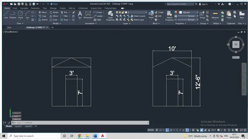
Explode the outer big rectangle and take an offset of the upper top line to a certain distance, towards inside so that the shape of roof is created for the wall.
Now, join again all the lines of outer rectangle.
Later trim the unwanted lines and form the structural shape as asked.
Give dimensions for better clarification.
Step:5
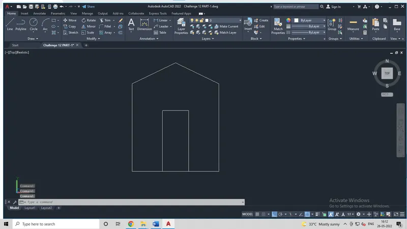
We get the required 2D structure as needed for the 3D model.
Step:6
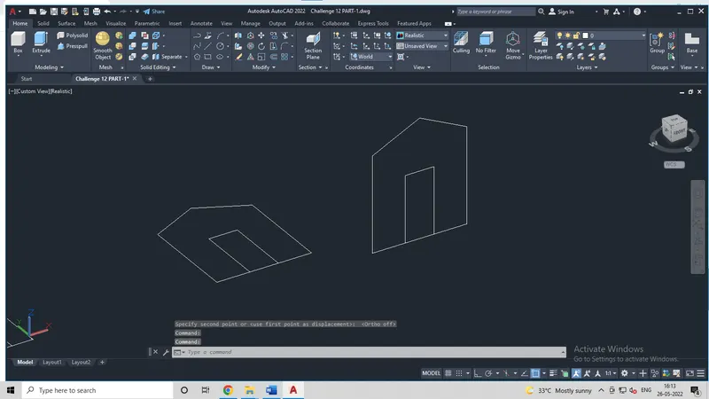
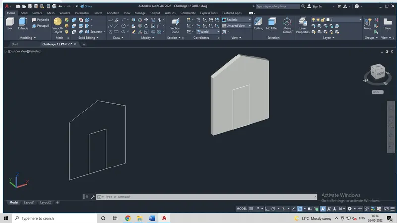
Use rotate 3D command and rotate the 2D structure at 90 degree and set the screen to view the 2 wire drawing properly.
Step:7
Use extrude command and extrude the outer boundary at a thickness of 9”.
Which is also represented in the below figure.
Step:8
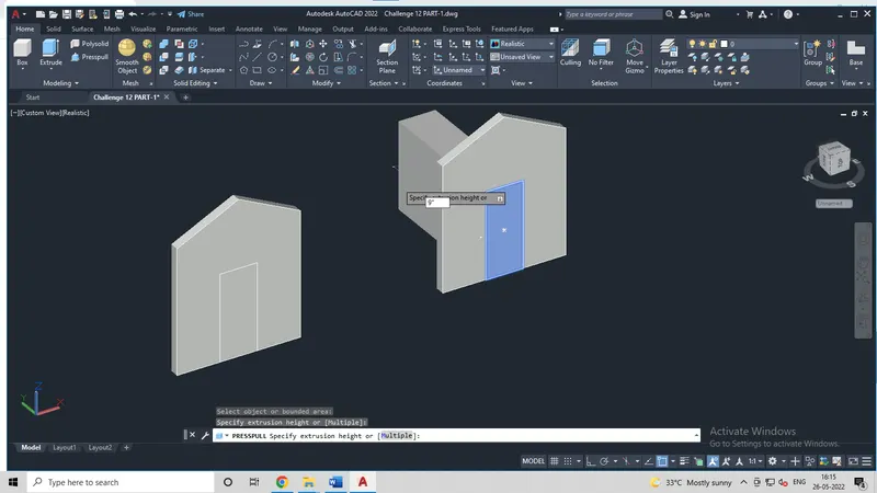
Use Press pull command and select the inner boundary and stretch towards any one side at 9” or more so that the center part is subtracted.
The same is shown in the below figure.
Step:9
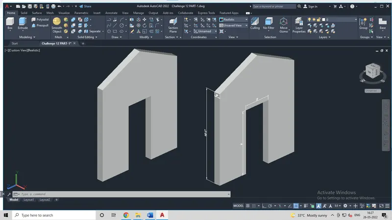
The final 3D view of the wall is obtained, also give dimensions.
The pictorial representation of the same is shown below.
Step:10
Color/ choose layer color for the furniture element according to your choice, which is totally optional.
Result:
Thus, the asked 3D model of a wall is created and visually represented below.