Creating various 3D Models like Furniture, Footing, Girder, Column drop with panel and Gable Wall in AutoCad
ANS.1.
AIM:-
To create a 3D furniture element using Autocad
INTRODUCTION:-
Using Autocad 3d Modelling to draw the given figure with commands
1.Extrude
2.Subtract
3.Box
4.Rectangle
5 Loft
6.Trim
7.Copy
8.Move
9.Cone
10.Union
11.Sweep
12.Boundary
13.Region
14.3dOrbit
15.USC
16.Offset etc.
PROCEDURE:-
1.Open Autocad, type UN to change the units into engineering so that the given figures unit matched at feet and inches.
2 go to 3D modelling option and then create a box with length 3 and width 2'6"
3. Also give the height as 2'6".
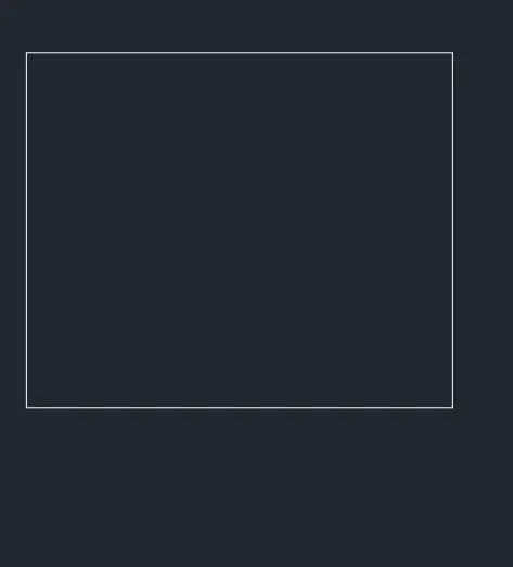
Then go to the front face of the box and place the ucs in the front face or use plan command for that.
After that draw a line of two inches from the right side of the rectangle and do the same for all the sides
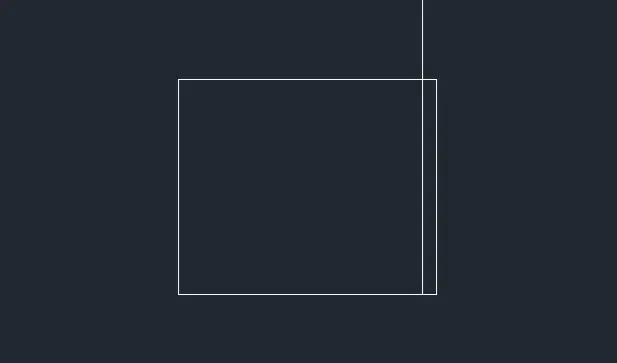
Then type 3DO for the 3D Orbit command to rotate the drawn figure in the three dimension.
Use the extrude command and first make the drawn line into a region and then use the extrud command
Extrude the selected region to 2'4" inside axis so that it should look like a 3D furniture.
Then give the command subtract and select the bigger box after that the smaller box that is student in 2D wireframe model.
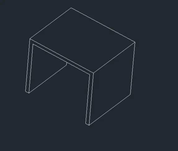
Dimensions can be given by dim linear command and they are given by switching the ucs as per the requirement.
RESULT :-
Created 3d furniture element is attached below
ANS.2.
AIM :-
To create a 3D model of an isolated footing using AutoCAD.
INTRODUCTION :-
Using Autocad 3d Modelling to draw the given figure with commands
1.Extrude
2.Subtract
3.Box
4.Rectangle
5 Loft
6.Trim
7.Copy
8.Move
9.Cone
10.Union
11.Sweep
12.Boundary
13.Region
14.3dOrbit
15.USC
16.Offset etc.
PROCEDURE :-
1.Open Autocad, type UN to change the units into engineering so that the given figures unit matched at feet and inches.
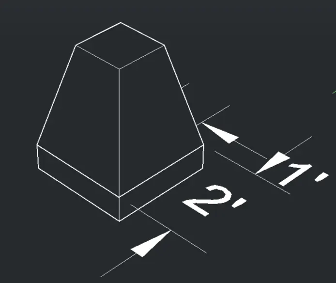
2 go to 3D modelling option and draw rectangle of dimension 2' ,2' in top view.
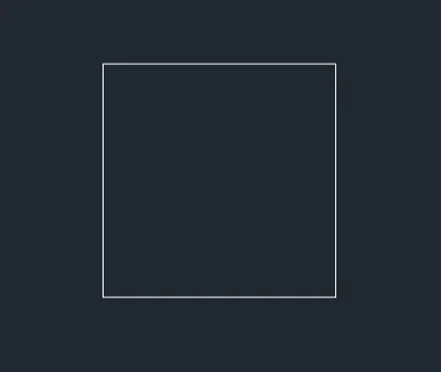
- Again create a rectangle of dimension 1' , 1' and place it in the centre of the created first rectangle
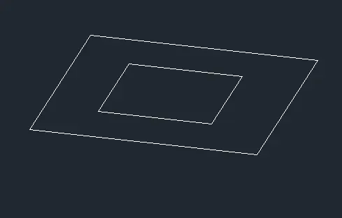
Then select the smaller rectangle and with command move, move the small rectangle by 2 inches in Z direction.
OrthoMode should be on otherwise the rectangle will go in any other direction
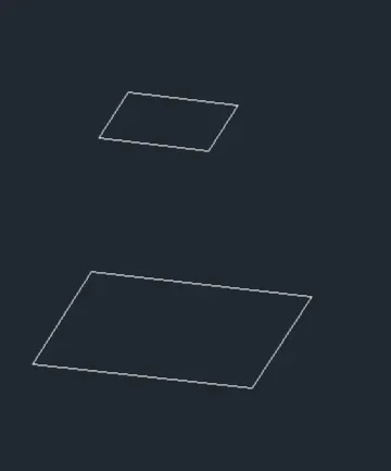
Use the command law of to join the to rectangles
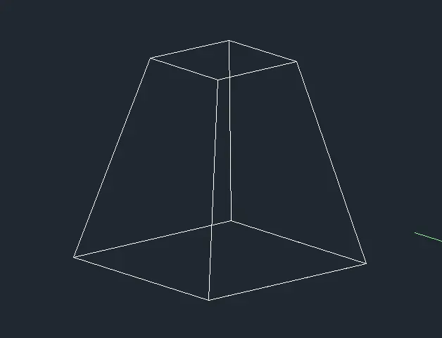
After that go to the top view again where you can see the lofted figure
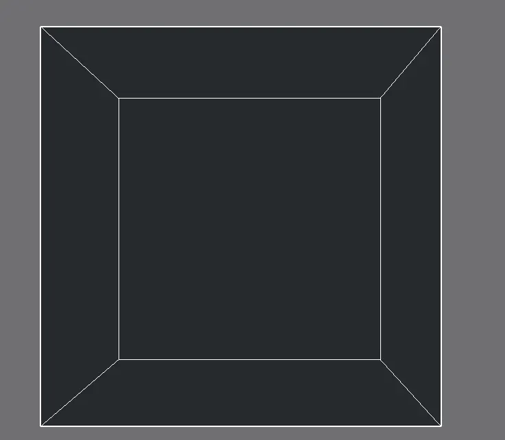
Use the dim linear command to dimension the drawn figure
RESULT :-
Created 3d model of isolated footing is attached below :-
ANS.3.
AIM:-
To create the 3D view of AASTHO type girder.
INTRODUCTION :-
Using Autocad 3d Modelling to draw the given figure with commands
1.Extrude
2.Subtract
3.Box
4.Rectangle
5 Loft
6.Trim
7.Copy
8.Move
9.Cone
10.Union
11.Sweep
12.Boundary
13.Region
14.3dOrbit
15.USC
16.Offset
PROCEDURE :-
Open Autocad, type UN to change the units into engineering so that the given figures unit matched at feet and inches.
Use the line tool and create a line of one inch in the top view in X direction and then again use the line tool to draw a Centre line of length 3feet
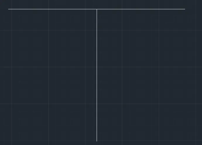
After that use the offset tool and offset the drawn line as per the given figure
Turn off the Ortho mode and join the lines in inclined position
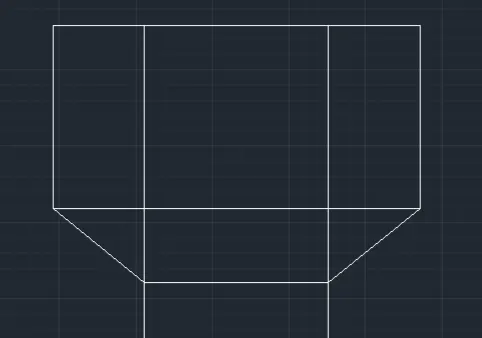
After that to create the base point from centre line of set the line 9' and 8' in left and same in right and then join
Use the trim command to trim the lines that are unnecessary
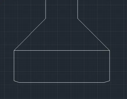
After trimming move the cursor to the view bar and switch the view into home and then the created figure will be seen like this
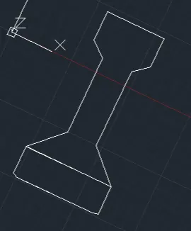
After that use the extrude command to extrude the created figure in z-axis and the length of extrusion will be 10 inch.
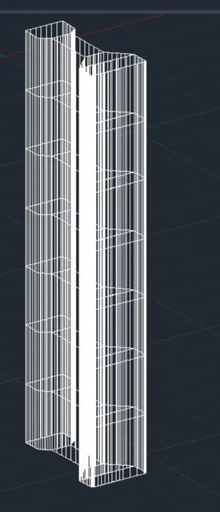
We can use the 3D face command to give the 3D face to the created figure
After extrusion is done then switch the view to realistic or conceptual or hidden to see the result figure.
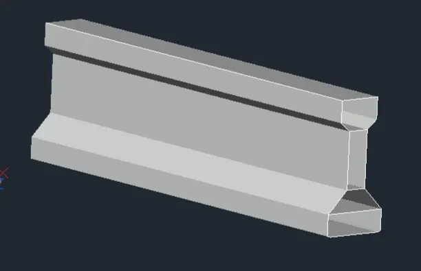
RESULT :-
Created AASTHO type girder is attached below :-
ANS.4.
AIM :-
To create the 3D model of a drop column with panel using AutoCAD
INTRODUCTION :-
Using Autocad 3d Modelling to draw the given figure with commands
1.Extrude
2.Subtract
3.Box
4.Rectangle
5 Loft
6.Trim
7.Copy
8.Move
9.Cone
10.Union
11.Sweep
12.Boundary
13.Region
14.3dOrbit
15.USC
16.Offset
PROCEDURE :-
Open Autocad, type UN to change the units into engineering so that the given figures unit matched at feet and inch.
Switch the mode into 3D modelling
Draw circle of diameter 1 feet 6 inches in x-axis
Then change the view and extrude the created circle in red access with height of 10 inches.
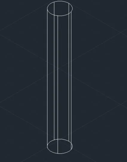
Then create a rectangle of dimension 4 feet 6 inches and 4 feet 6 inches and then copy the drawn rectangle in Z axis with height of 6 inch
Now to join the rectangles use the law of command and select both of the rectangles to join.
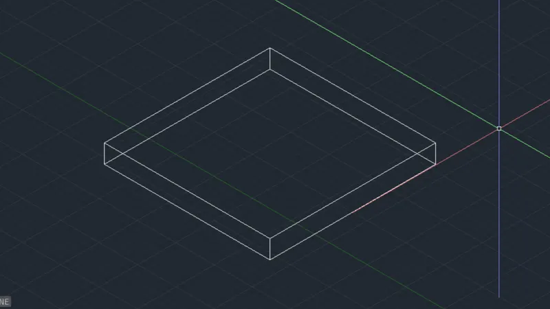
Then select the cone tool or give the cone command to draw cone with inner diameter of 1 feet 6 inches and Outer radius of 1 feet 6 inches.
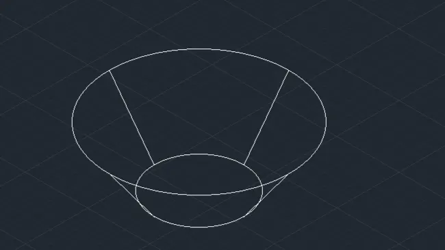
now switch to the top view
Place the created cone in the centre of the drawn rectangle.
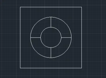
Also place the circle that is extruded in the starting and it should be carefully placed in the centre of the rectangle
Then switch to the home view to see the created figure
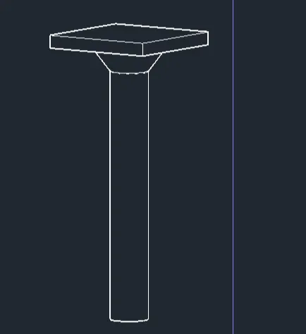
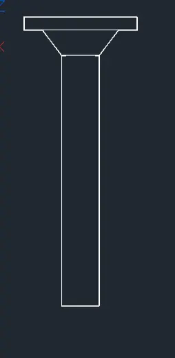
This is the front view of the created figure.
RESULT :-
Created 3d model of drop column with panels is attached below :-
ANS.5.
AIM :-
Create 3D model of the wall using the AutoCAD considering wall thickness as 9 inch.
INTRODUCTION :-
Using Autocad 3d Modelling to draw the given figure with commands
1.Extrude
2.Subtract
3.Box
4.Rectangle
5 Loft
6.Trim
7.Copy
8.Move
9.Cone
10.Union
11.Sweep
12.Boundary
13.Region
14.3dOrbit
15.USC
16.Offset
PROCEDURE :-
Open Autocad, type UN to change the units into engineering so that the given figures unit matched at feet and inches
Switch to the 3D modelling mode
Draw a rectangle of size 10 inches using the rec command.
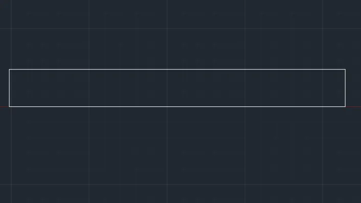
From the centre of the rectangle create two of sides one in the right and one in the left with distance 1 feet 6 inch.
Use command region to select the region of the both offsetted rectangles.
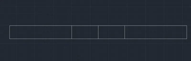
After creating the regions select both the rectangles and extrud them in the Z axis as length 12 feet 6 inches
After the extrution , go to the front view and then create two parallel lines for the roof at an inclination of 30 degree.
Then select the created parallel lines and copy them in Z axis.
Select the created lines and make them region by giving region command.
After that use the subtract command to delete the other portion of the figure
Select the bigger part first and then select the smaller portion and then subtract
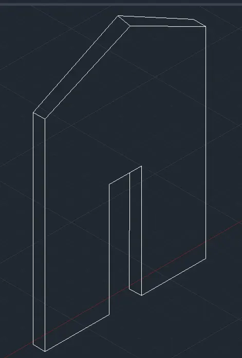
Use the dimension tool to dimension the drawn figure.
RESULT :-
Created 3d model of wall is attached below :-