Creating various 3D Models like Furniture, Footing, Girder, Column drop with panel and Gable Wall in AutoCad
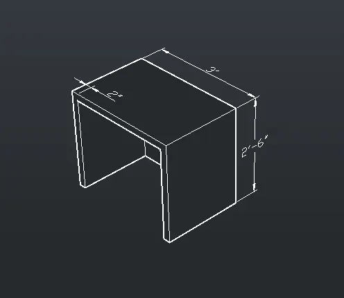
AIM-1:Create a 3D Furniture element as shown in the Figure. Assume dimensions which are missing by autocad.
INTRADUCTION:
- Draw any furniture element in mathamatical repramentation by a software that autocad
- if the furniture element made in 3dimention by the help of different commands by this software.
- this software is related to draw a 2D and 3D images.
PROCEDURE:
STEP-1
- Open new drawing page in autocad.
- enter UNITS command and set units as FEET and INCHES.
- set the limax value as 50' x 50'.
- work spece switching into 3D MODELLING.
- enable the view cube in icon in ribbion.
STEP-2
- enter REC command in commnad bar select the first poin some wher in display after enter the value of @2'6",3'.
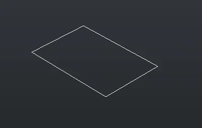
- enter EXTRUDE command select the rectangle enter entere extrude height 2'6" enter we get a cube of solid created.
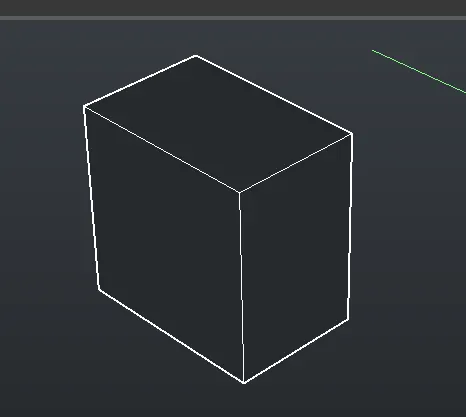
- now enter 2D WIREFRAME model that cube.
- after that enter UCS command select FACE in it. place the ucs in to lift side face of cube in X-Y FACE like top-Y and right-x.
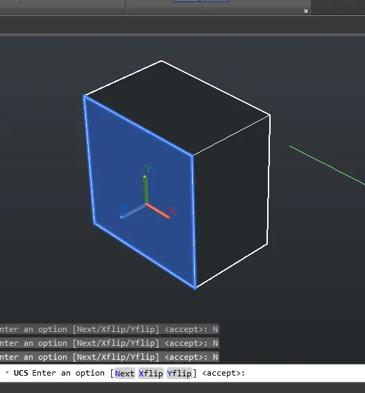
- draw the offset lines of 2" space except bottom line draw a rectangle in that face
- after that region that internal rectangle.
- that REGION rectangle extrude in to 2'4" to wards -z axies.
- after that SUBTRACT that internal rectangle from outer rectangle.
- after that that we get required furniture.
- apply the dimentions by DIMLINEAR command.
RESULTS:
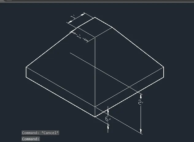
AIM-2:Create the 3d Model of an Isolated footing as shown in Figure.
INTRADUCTION:
- Draw any furniture element in mathamatical repramentation by a software that autocad
- if the furniture element made in 3dimention by the help of different commands by this software.
- this software is related to draw a 2D and 3D images.
PROCEDURE:
STEP-1
- Open new drawing page in autocad.
- enter UNITS command and set units as FEET and INCHES.
- set the limax value as 50' x 50'.
- work spece switching into 3D MODELLING.
- enable the view cube in icon in ribbion.
STEP-2:
- draw a rectangle size of 1'x1'
- offset the rectangle with the dimention of 1'6"
- move the internal rectangle towards Z-AXIES or upwards height of 2'6"
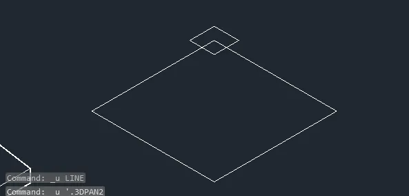
- outer rectangle extrude through the Z-AXIES or upwards height of 6"
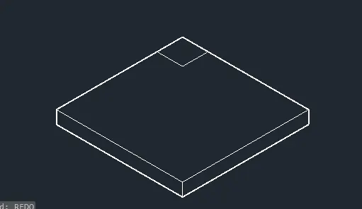
- after that enter 3DFACE command and create the faces of every rectangle.
- apply the dimentions by DIMLINEAR command.
RESULTS:
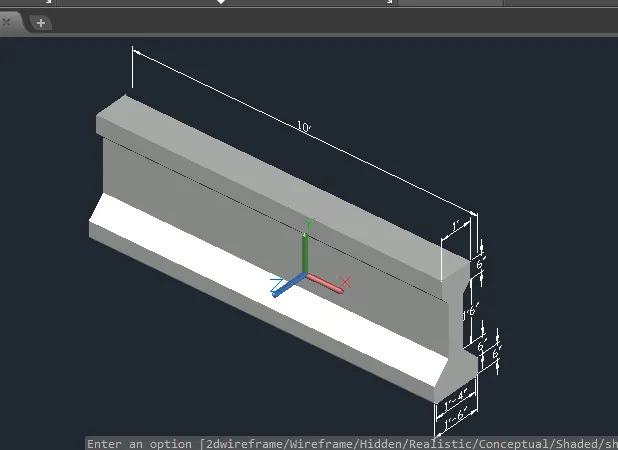
AIM-3:Create the 3D view of the AASTHO Type Girder.
INTRADUCTION:
- Draw any furniture element in mathamatical repramentation by a software that autocad
- if the furniture element made in 3dimention by the help of different commands by this software.
- this software is related to draw a 2D and 3D images.
PROCEDURE:
STEP-1
- Open new drawing page in autocad.
- enter UNITS command and set units as FEET and INCHES.
- set the limax value as 50' x 50'.
- work spece switching into 3D MODELLING.
- enable the view cube in icon in ribbion.
STEP-2:
- Using line command draw a AASTHO Type Girder.
- mention first poin some where in page.
- choose 2nd point towards X-AXIES as length as 1'6"
- next point towards Z-AXIES as length as 6"
- next point towards negetive X-AXIES as length as 6" with angle of 135 degrees.
- next point towards Z-AXIES as length as 1'6"
- next point towards Z-AXIES as length as 3' with angle of 45 degres.
- next point towards negetive x-AXIES as length as 1'
- next point towards negetive Z-AXIES as length as 6"
- next point towards negetive Z-AXIES as length as 3" with angle of 315 degree
- next point towards nagetive Z-AXIES as length as 1'6"
- next point towards nagetive Z-AXIES as length as 6" with a angle of 225 degree.
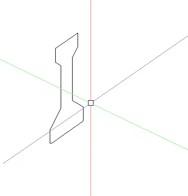
- REGION all elements in aastho type grider.
- after that EXTRUDE the element 10' back-side (towards Y-AXIES).
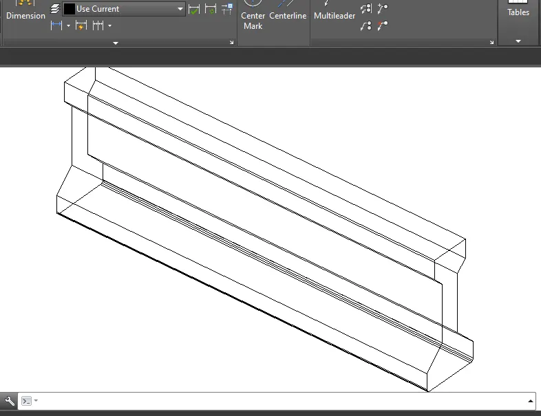
- with using UCS command apply dimentions
- REQUIRED DRAWING 3DIMENTIONAL IS CREATED
RESULTS:
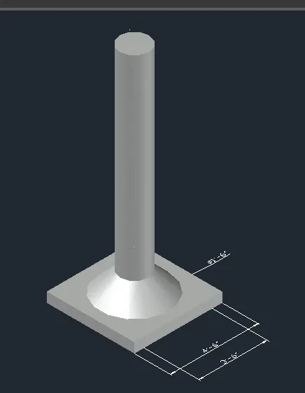
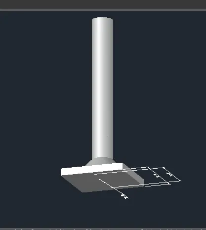
AIM-4:Create a 3d Model of a drop column with panel as shown in section and isometric view.
INTRADUCTION:
- Draw any furniture element in mathamatical repramentation by a software that autocad
- if the furniture element made in 3dimention by the help of different commands by this software.
- this software is related to draw a 2D and 3D images.
PROCEDURE:
STEP-1
- Open new drawing page in autocad.
- enter UNITS command and set units as FEET and INCHES.
- set the limax value as 50' x 50'.
- work spece switching into 3D MODELLING.
- enable the view cube in icon in ribbion.
STEP-2:
- Draw a sqare of 4'6" x 4'6" after that EXTRUDE that square into height of 6".
- then we draw a cone shaped element with upper radious of 9" and bottom dia of 3'6" with CONE command in command bar
- Select the cone from ribbon < solid < select piramid < base dia 3'6" < select top dia 1'6"< enter.cone shaped element is created.
- select cylinder from ribbon < solid <select cylinder < enter dia of 1'6".
- after add cylinder with base center point to upper 1'6" cone upper center point UNION both the elements.
- this combined element add top centre of solid square.
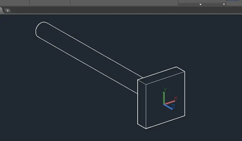
- add dimention with comman dof DIMLINEAR.
RESULTS:
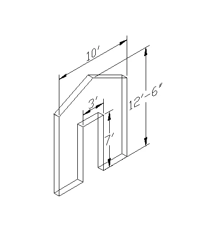
AIM-5:Create the 3d model of a wall as shown in Figure. Consider wall thickness as 9”.
INTRADUCTION:
- Draw any furniture element in mathamatical repramentation by a software that autocad
- if the furniture element made in 3dimention by the help of different commands by this software.
- this software is related to draw a 2D and 3D images.
PROCEDURE:
STEP-1
- Open new drawing page in autocad.
- enter UNITS command and set units as FEET and INCHES.
- set the limax value as 50' x 50'.
- work spece switching into 3D MODELLING.
- enable the view cube in icon in ribbion.
STEP-2:
- select line command draw arectangle X-Z PLANE height of 10' above that draw triangle with that place in that upper base with height of 2'6".
- in the rectangle draw other rectangle as a 3' x 7' middle of rectangle on base.
- after that extrude that whole element throught the Y-AXIES thickness as 9".
- apply dimention by the DIMLINEAR command.
RESULTS: