Creating various 3D Models like Furniture, Footing, Girder, Column drop with panel and Gable Wall in AutoCad
Creating various 3D Models like Furniture, Footing, Girder, Column drop with panel and Gable Wall in AutoCad
Jagadeep.M.M
AIM:
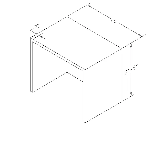
Create a 3D Furniture element.
PROCEDURE:
Step 1
- Open autocad softwere, type QNew incommand box,press enter.
- Click on the workspace switching & change it to 3d modelling.
- Select default setting as imperial setting.
- Drawing units setting as length=(Engineering),precision=0'0.0", Ok
- Drawing limits setting as, specify the lower left corner=enter,upper right corner=100',100',enter.
- Type the command box Dimension style manager & press enter.
- enter modify-enter primary units-unit format=Engineering, precision=0'0.0",enter Ok.
Step 2
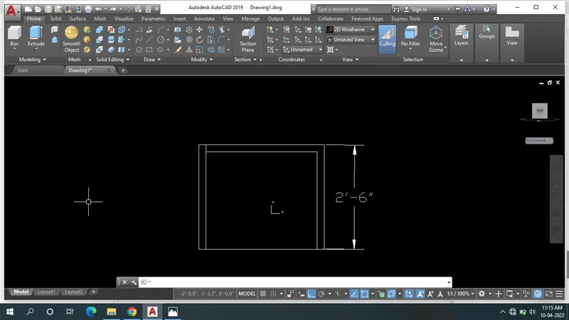
- Create the box using box command or toolbar , click on length, give the length as 3' & width as 2'6", height as 2'6".
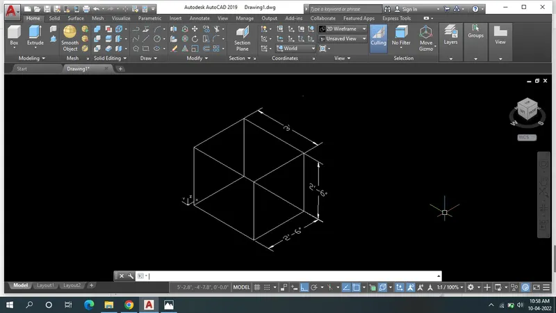
- Type the "ucs" command, click on the "Face", give the X & Y coordinate in the front face horizontally & vertically then select the front face.
- Type the command "Plan" so that front face is aligned correctly.
- Draw a line of 2" from the left side of the front view.
- By rectangle command draw the rectangle of the dimension as @2'8",2'4".
Step 3
- Delete the line created earlier, & delete the bottom front face line.
- Now with command "3do"orbit the object & select the rectangle.
- Extrude the rectangle to -Z axis -2'4".
- Now give the command "subtract" select the larger object then the smaller extruded rectangle in 2d wireframe model.
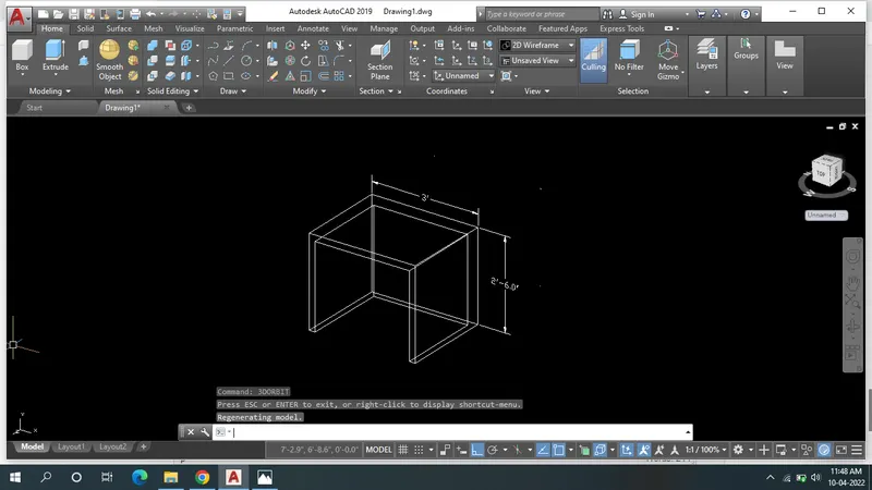
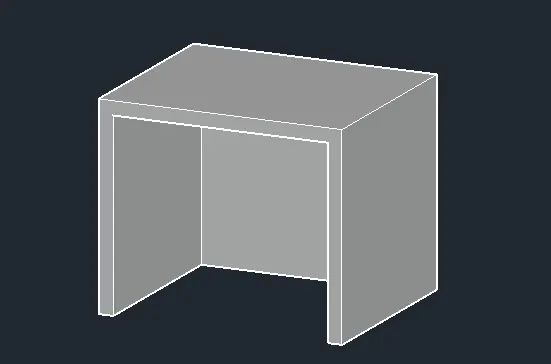
- change the visual style as Hidden.
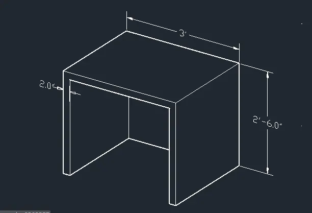
- dimension using dimension command.
Result
AIM:
Create the 3d Model of an Isolated footing.
PROCEDURE:
Step 1
- Open autocad softwere, type QNew incommand box,press enter.
- Click on the workspace switching & change it to 3d modelling.
- Select default setting as imperial setting.
- Drawing units setting as length=(Engineering),precision=0'0.0", Ok
- Drawing limits setting as, specify the lower left corner=enter,upper right corner=100',100',enter.
- Type the command box Dimension style manager & press enter.
- enter modify-enter primary units-unit format=Engineering, precision=0'0.0",enter Ok.
Step 2
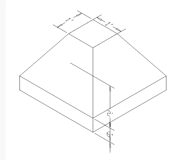
- Create a rectangle of 2'X2' on the top view.
- Create the another rectangle of 1'X1' on the top view of middle part.
- Movie the smaller rectangle of 1' in +Z direction with ortho on.
- Give the extrude command & extrude the 2'X2' rectangle extrude it 6" in the -Zdirection.
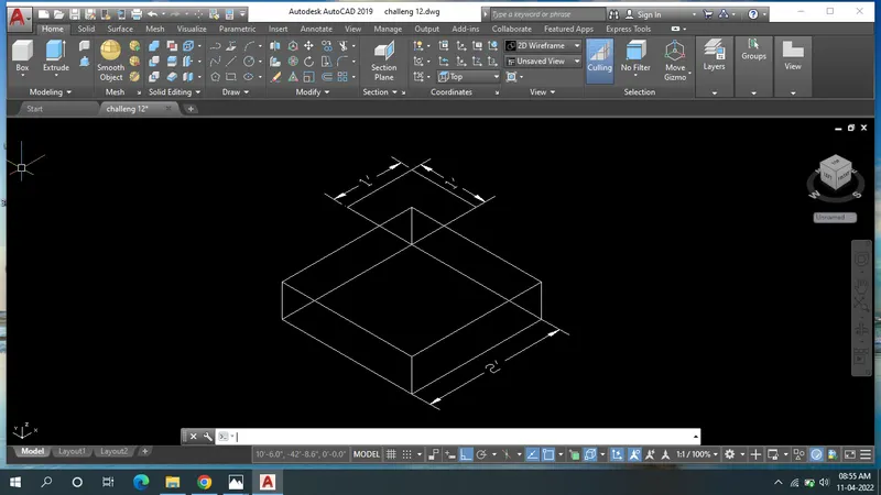
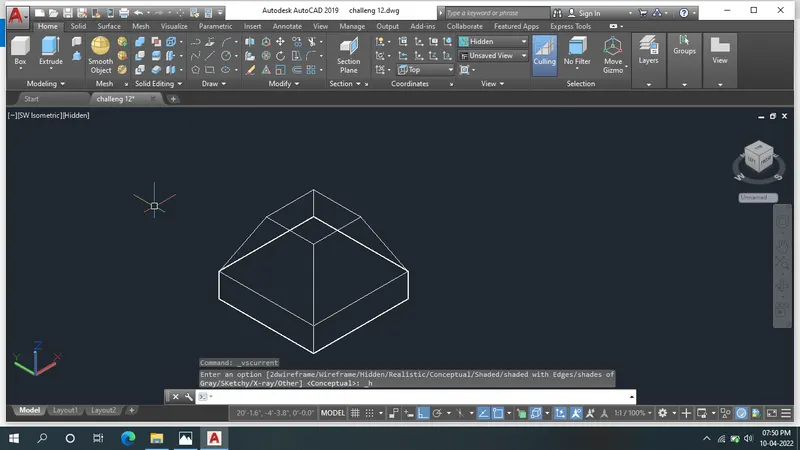
- join the corner side using the line command.
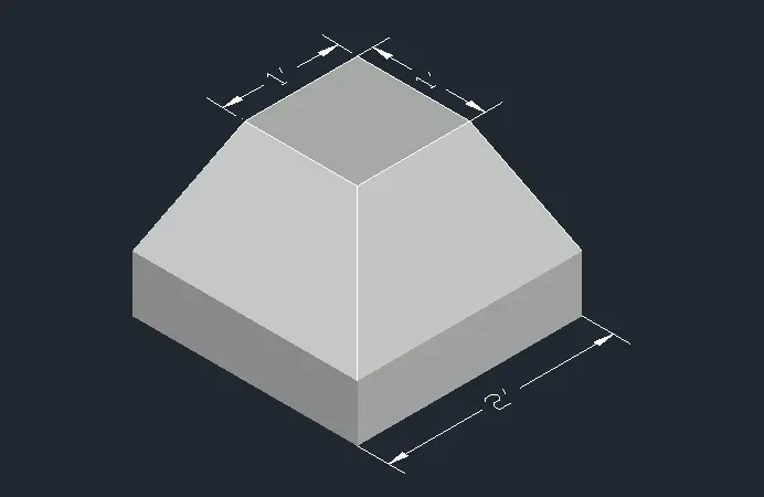
- Give the dimensions.
Result
AIM:
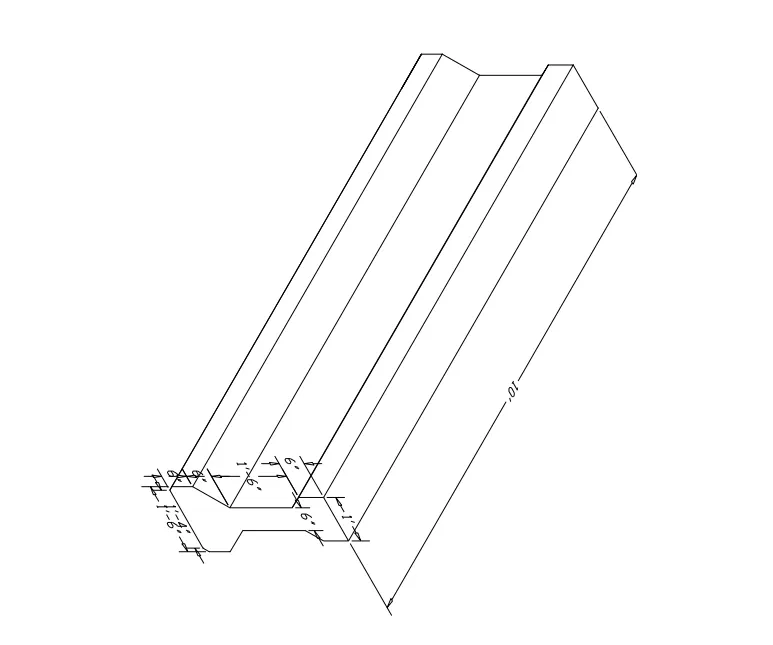
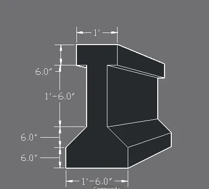
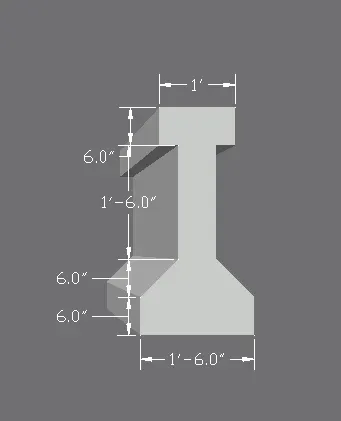
Create the 3D view of the AASTHO Type Girder.
PROCEDURE:
Step 1
- Open autocad softwere, type QNew incommand box,press enter.
- Click on the workspace switching & change it to 3d modelling.
- Select default setting as imperial setting.
- Drawing units setting as length=(Engineering),precision=0'0.0", Ok
- Drawing limits setting as, specify the lower left corner=enter,upper right corner=100',100',enter.
- Type the command box Dimension style manager & press enter.
- enter modify-enter primary units-unit format=Engineering, precision=0'0.0",enter Ok.
Step 2
- open the top view & 2D wireframe.
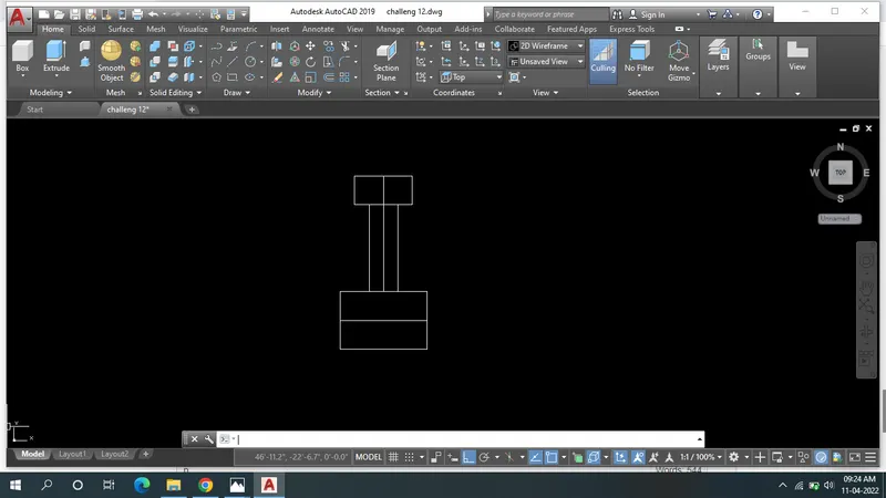
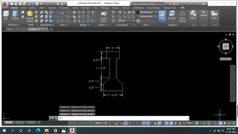
- draw the rectangle of @1'6"X6", again draw the above at @1'6",6".
- above the rectangle draw the middle line of 1'6" & give the offset of 3" in both sides.
- above the middle line as 6" & givre the offset of 6" in both sides.
- join the line using line command.
Step 3
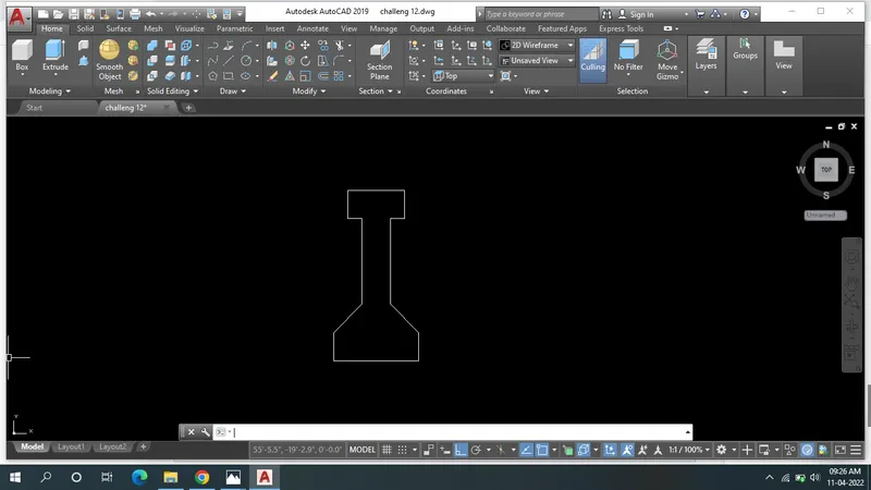
- Trim the unwanted line.
- type the region & select the drawing.
- go the 3 model & use the extrude command & extrude it 10'.
- use the dimension.
- use the 3D orbit & chnage the hidden.
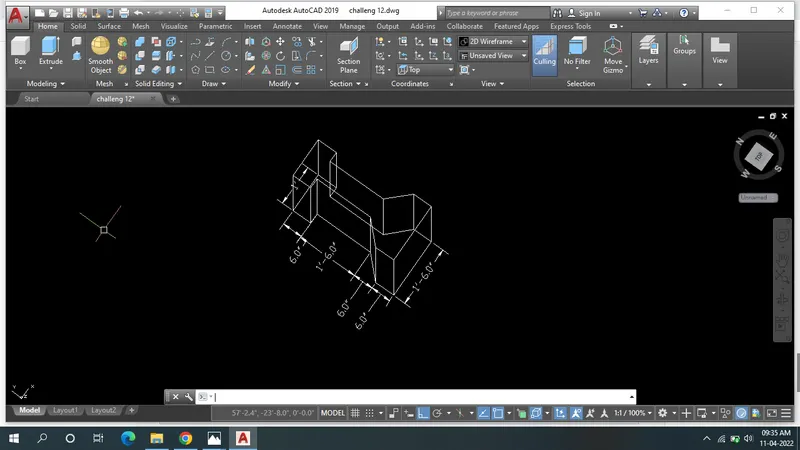
Result
AIM:
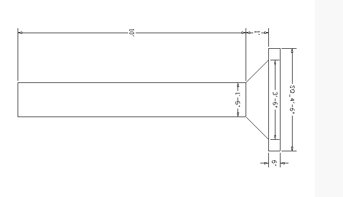
Create a 3d Model of a drop column with panel as shown in section and isometric view.
PROCEDURE:
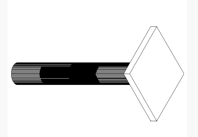
Step 1
- Open autocad softwere, type QNew incommand box,press enter.
- Click on the workspace switching & change it to 3d modelling.
- Select default setting as imperial setting.
- Drawing units setting as length=(Engineering),precision=0'0.0", Ok
- Drawing limits setting as, specify the lower left corner=enter,upper right corner=100',100',enter.
- Type the command box Dimension style manager & press enter.
- enter modify-enter primary units-unit format=Engineering, precision=0'0.0",enter Ok.
Step 2
- Create a circle of dimension 1'6" in the top view.
- Create a region command & select the circle.
- Extrude with the extrude command give the distance of 10'.
- Create a cone by clicking on cone from the home tab.
- Click on the diameter & give the base diameter as 1'6".
- Click on the tp the cone as 2'1".
- Give the height of the cone as 1' in -Z direction.
- creare the rectangle in top view as 4'6"X4'6".
- Give the offset of 6" inside.that will be a 3'6"X3'6".
- click on the 3d view.
- IN the tpo view place the rectangle at the center of the cone & also adjust in front views give move command, the rectangle is at bottom in front view.
- use the dimension using dimension command.
Result
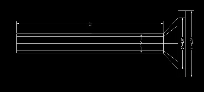
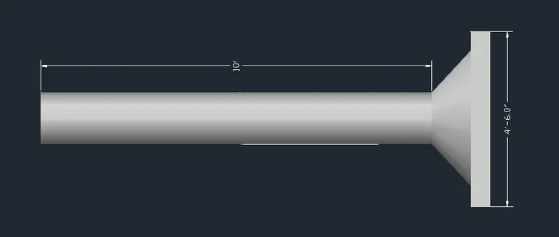
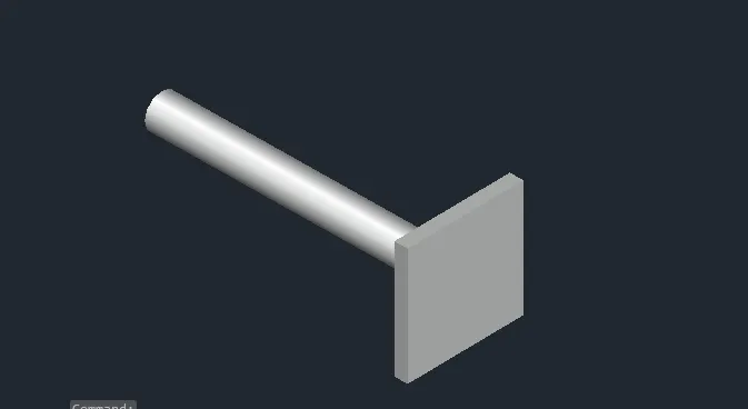
AIM:
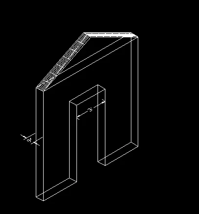
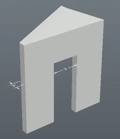
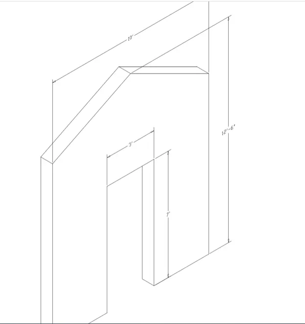
Create the 3d model of a wall.
PROCEDURE:
Step 1
- Open autocad softwere, type QNew incommand box,press enter.
- Click on the workspace switching & change it to 3d modelling.
- Select default setting as imperial setting.
- Drawing units setting as length=(Engineering),precision=0'0.0", Ok
- Drawing limits setting as, specify the lower left corner=enter,upper right corner=100',100',enter.
- Type the command box Dimension style manager & press enter.
- enter modify-enter primary units-unit format=Engineering, precision=0'0.0",enter Ok.
Step 2
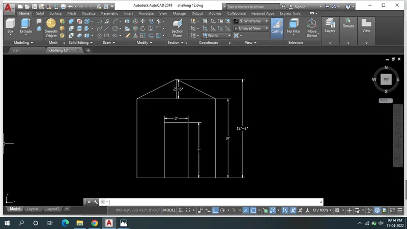
- Create the rectangle of 10'X10' in the top view.
- Create the rectangle of 3'X7' & movie the rectangle in the bottom of center point.
- draw the line above the 10'X10' rectange in the center line distance is 2'6".
- join above corner line in the center line upper point.
Step 3
- Trim the unwanted lines.
- Create the region using command.
- click the extrude command & extrude the distance will be 9".
- use the 3d rotate toolbar & rotate it.
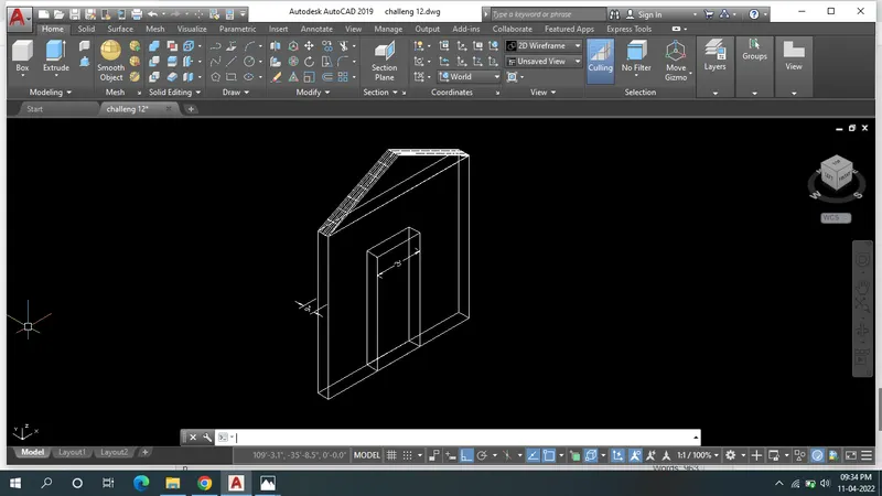
- click the subtract command & subtract the door of 3'X7'.
- use the dimension using dimension command.
- chane the visual style.
Result