Creating various 3D Models like Furniture, Footing, Girder, Column drop with panel and Gable Wall in AutoCad
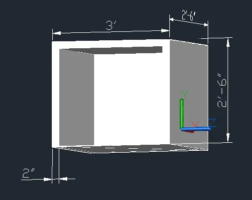
AIM_1: Create a 3D Furniture element as shown in the Figure. Assume dimensions that are missing
INTRODUCTION: In the following question, the main aim is to create a 3D furniture element. In this, commands like box, 3DPOLY, region, and subtract were used. Please refer to the below snips for more clarity.
PROCEDURE:
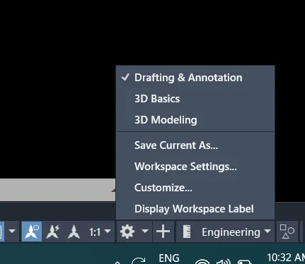
- Go to the setting section in the bottom right corner of the screen, as shown in the snip, and select the 3D basic or 3D modeling option from the menu.
- Now the AutoCAD file can be drafted in #D.
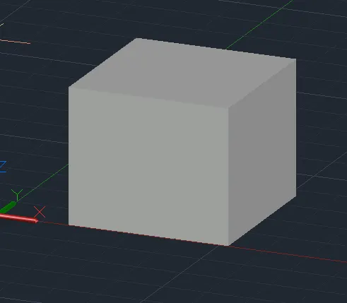
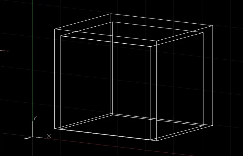
- Now using the box command create a box as per the given dimensions in the question.
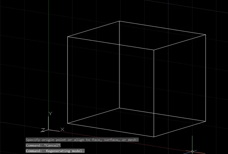
- Once the box is drawn, using a 3D polyline, draw an outline for the thickness of the table.
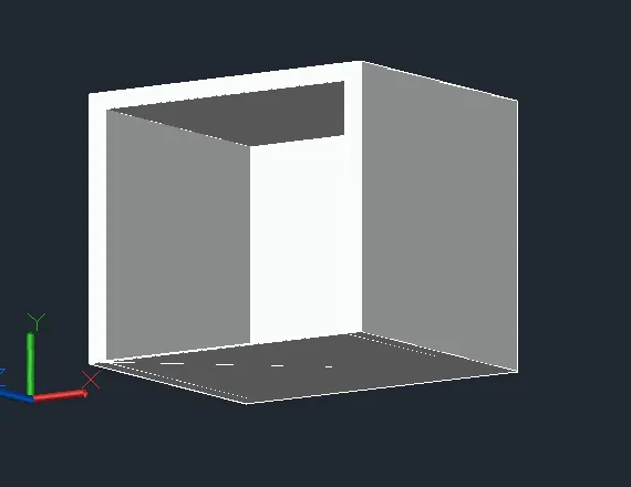
- Now Draw another box of the dimension such that, when substract command is used and the second box is substracted, the product should be the model of furniture as asked in the question.
- Give The dimensions wherever required.
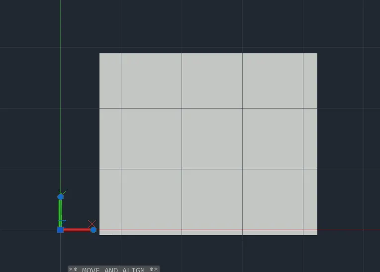
RESULTS: The 3D model of the furniture is drawn as per the given dimensions. Please refer to the below snips for more clarity.
SNIPS:
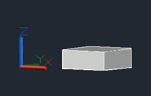
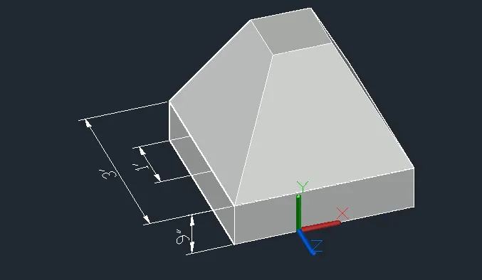
AIM_2: Create the 3d Model of an Isolated footing as shown in Figure.
INTRODUCTION: In the following question the main aim is to create a 3D model of a footing. The footing is created using rectangle, region, presspull, and pyramid commands. Please refer to the below snips for more clarity.
PROCEDURE:
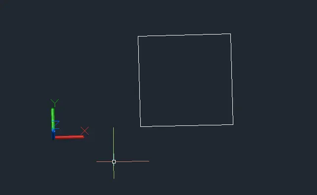
- Draw a rectangle of given dimensions in the challenge.
- Convert the rectangle to the region using the region command.
- Now use the presspull command and stretch the region to a height of 9".
- Now take the pyramid command.
- Select the edge option, and mention the starting point by clicking on any of the corners of the presspulled cuboid.
- Now give the edge distance and then mention the upper radius of 6".
- Thus the figure asked is formed.
- Give the required dimension
RESULTS: The 3D model of an isolated footing is created as asked in the challenge. Please refer to the below snips for more clarity.
SNIPS:
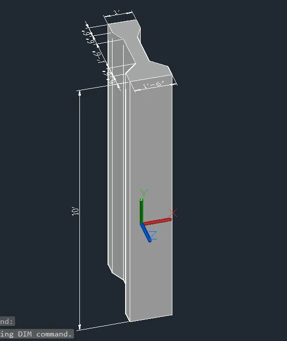
AIM_3: Create the 3D view of the AASTHO Type Girder.
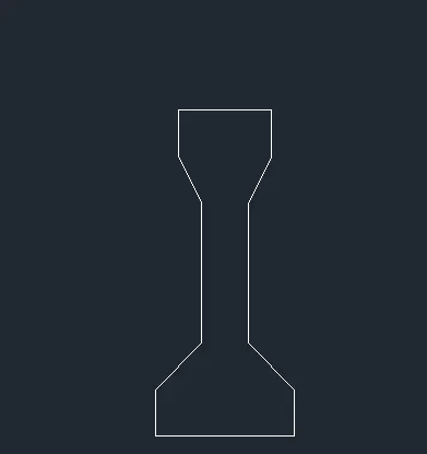
INTRODUCTION: In the following question, the main aim is to create an I girder's 3D model. In this commands like line, region, and presspull were used. Please refer to the below snips for more clarity.
PROCEDURE:
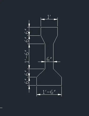
- Draw the sectional geometry of the I girder using the line command in the XY plane.
- Give the dimensions of the geometry.
- Now convert the geometry into a region using the region command.
- Once the region is created, presspull the region to a length of 10'.
- Give the required dimension
RESULTS: The required model of the 10' length I girder is formed. Please refer to the below snips for more clarity.
SNIPS:
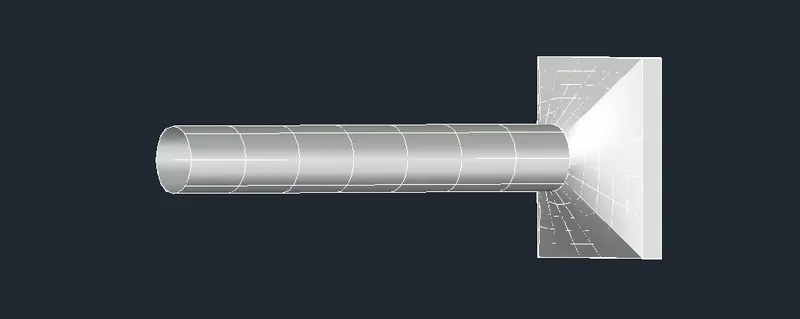
AIM_4: Create a 3d Model of a drop column with the panel as shown in the section and isometric view.
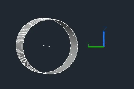
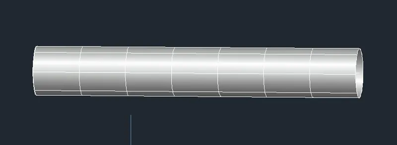
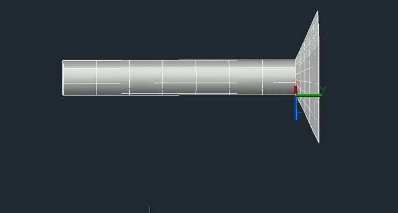
INTRODUCTION: In the following question the main aim is to create a 3D model of a column with a drop panel. The commands like revolve, loft, region, presspull, rectangle, circle, etc were used. Please refer to the below snips for more clarity.
PROCEDURE:
- In the XY plane draw a line of 10', and take the offset of the same at a distance of 9".
- Now using revolve command create a cylindrical geometry.
- Now use UCS command and change the plane of plotting and draw a circle and square of required lengths, having same centre.
- Now Use move command to move the rectangle.
- Now use the loft command to draw a surface from circle of the cylinder to the square.
- Now make that square a region using region command and presspull it to required thickness.
- Thus the required figure is drawn.
RESULTS: The 3D model of a drop column with panel is created as asked in the challenge. Please refer to the below snips for more clarity.
SNIPS:
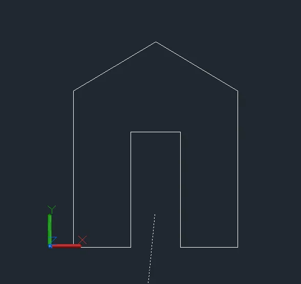
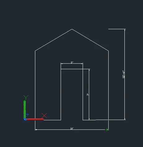
AIM_5: Create the 3d model of a wall as shown in Figure. Consider wall thickness as 9”.
INTRODUCTION: In the following question the main aim is to create a 3D model of a wall having a thickness of 9". Commands like region, polyline, presspull, rectangle, etc were used. Please refer to the below snips for more clarity.
PROCEDURE:
- Draw a 2D figure of the wall in XY plane as asked in the challenge.
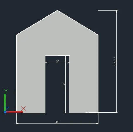
- Now once the whole figure is drawn, create the figure into a region using the region command.
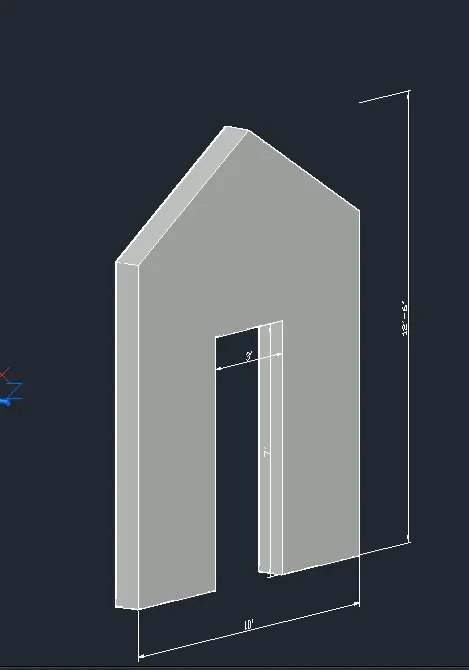
- Now presspull the region to a thickness of 9".
- Give the required dimensions.
RESULTS: The 3D model of the wall as asked in the challenge is drawn. Please refer to the below snips for more clarity.
SNIPS: