Creating various 3D Models like Furniture, Footing, Girder, Column drop with panel and Gable Wall in AutoCad
Aim: To create the various 3D models like furniture, fotting, girder, column drop with panel and gable wall in Autocad
Introduction:
3d modelling is a process of representation of an any surface of an object in three dimensional. using the 3d model the user can get more evocative design, and they can even see the virtual images of their projects. The user can see the impact of all the minor and major changes made in the 3d model. this also aids in the better finishing of the designs without wasting time and money. It is advantages to interior designers as they get to create and then modify 3D interior as well as exterior as per their needs and choice. In a 3d design the user get to know physical dimensions of the objects and their distance to in relation to other object in the layout. this feature helps enormously to see and modifyb the arrangements of the object.
Commands used:
- Units command
- Rectangle
- Circle
- Line
- Offset
- 3d face
- region
- Boundary
- Extrude
- sweep
- Move Faces
- Copy
- UCS
1. Creation of the 3d furniture
- Open the autocad new file slect the imperial.
- UN enter select the engineering and select the precission.
- From status bar select the workspace to 3d modelling.
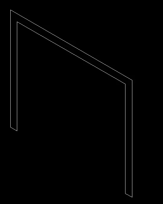
- select the line command give the starting point.
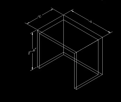
- next point as a @0,0,2'6", @ 0,-3',0 , @ 0,0,-2'6", @0,2",0 , @ 0, 0, 2'4" , @ 0,2'8",0 , @0,0, -2'4" and join the starting point.
- Copy the this object at a distance of @ 2',0,0
- By using the line command all points are joined
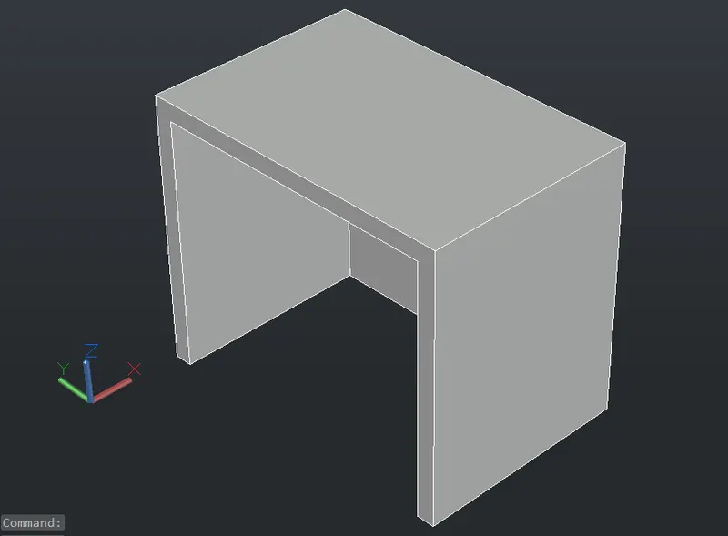
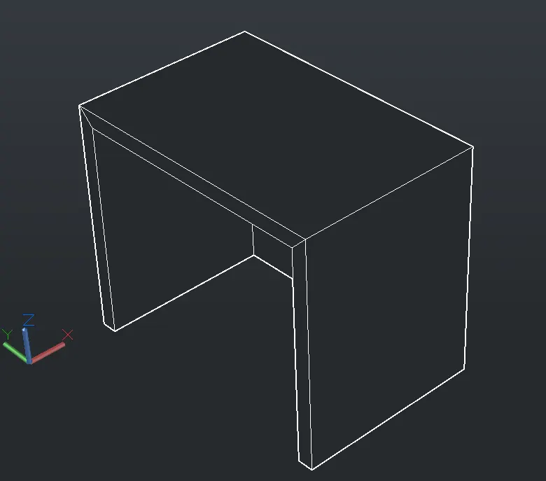
- By using the 3Dface command the the 2D wirefarame is converted into solid surface.
- Using the dimlinear command the dimensions are given.
- By changing the UCS the vertical dimensions are given.
Result:
2. Create the 3d model of an isolated footing
- Open the autocad new file slect the imperial.
- UN enter select the engineering and select the precision.
- From status bar select the workspace to 3d modelling.
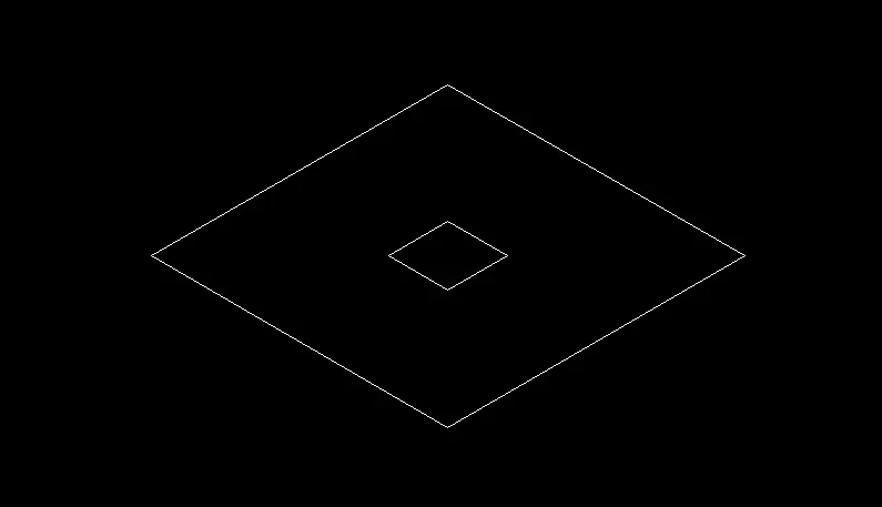
- Draw the rectangle of the size 1' x 1'
- Offset this rectangle by 1' outwards
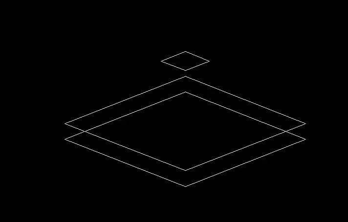
- move the centre rectangle at a distance of @0,0,2'
- Copy outside rectangle and placed it @0,0,-6"
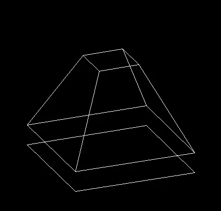
- Join all these corner by using the line command.
- By using the 3dface command the 2d wireframe edges is converted into the solid face.
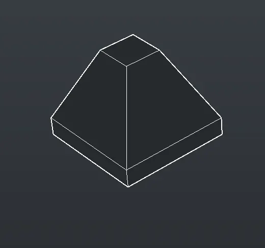
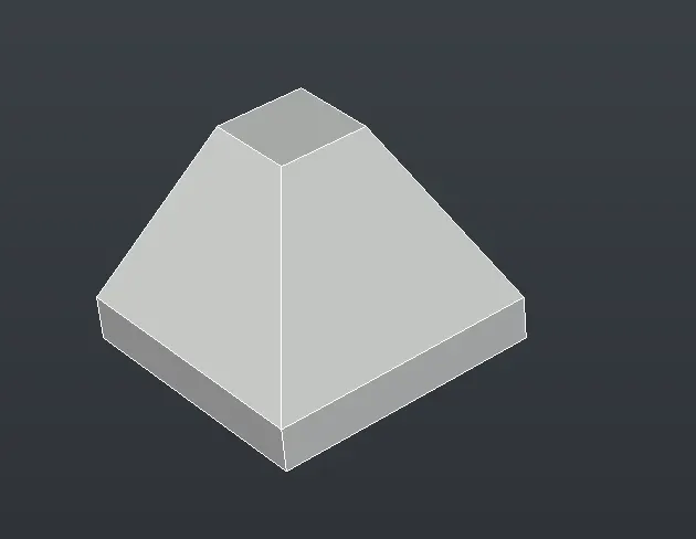
Result:
3. Create the 3D view of AASTHO type girder
- Open the autocad new file slect the imperial.
- UN enter select the engineering and select the precision.
- From status bar select the workspace to 3d modelling.
- UCS enter change the cordinate system with y axis as vertical.
- Type plan in the command box enter select the currennt Ucs system amd draw the girder.
- select the line command give the starting point of the line then next line is length is given by moving the cursor the length of the line is given.
- By using the dimlinear command the dimensions are given.
- REGION enter select the whole object enter. This is cinverted into the solid face.
- By using the EXTRUDE command the solid is created and give length as 10'.
- Select the shaded option from the viewport controls.
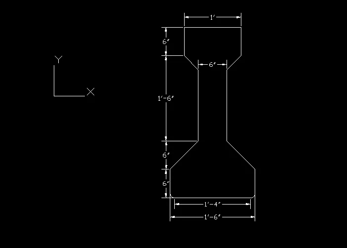

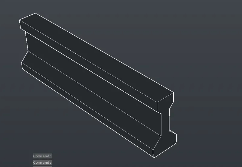
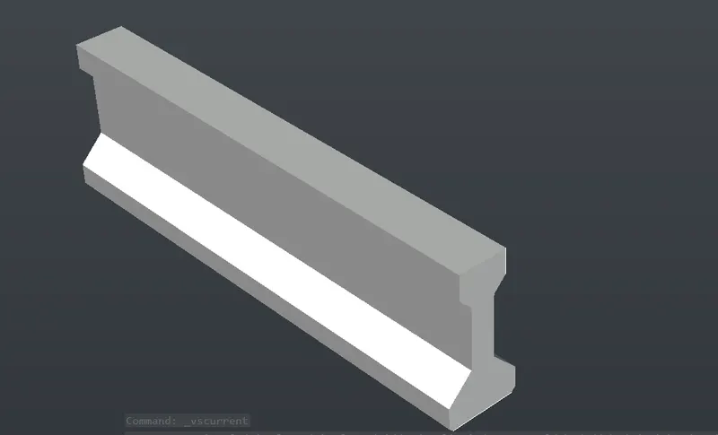
Result:
4. Creation of a 3d model of the drop column with panel
- Open the autocad new file slect the imperial.
- UN enter select the engineering and select the precision.
- From status bar select the workspace to 3d modelling.
- type ucs in command box enter change coordinate system.
- Type plan enter select the current ucs system.
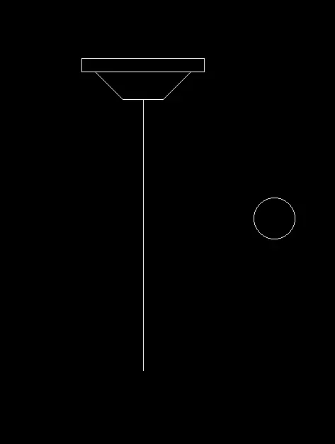
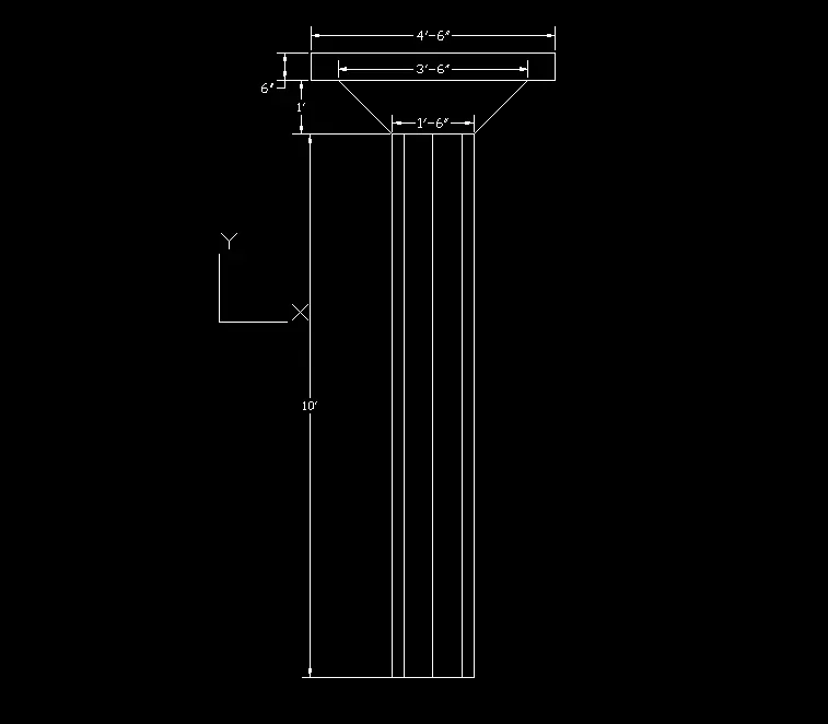
- Draw the rectangle of the size 4'6" x 6"
- Explode the rectangle and offset the bottm line of the rectangle at offset distance of 1' downward.
- select the line command starting point of the line 6" right side from bottom corner.
- draw the line at an angle of 315 degree and 1'6" horizontal line and at 45 degree join the top line. erase the offseted line.
- Draw the line of the length 10' downward as shown in figure.
- Draw the circle of the diameter of 1'6"
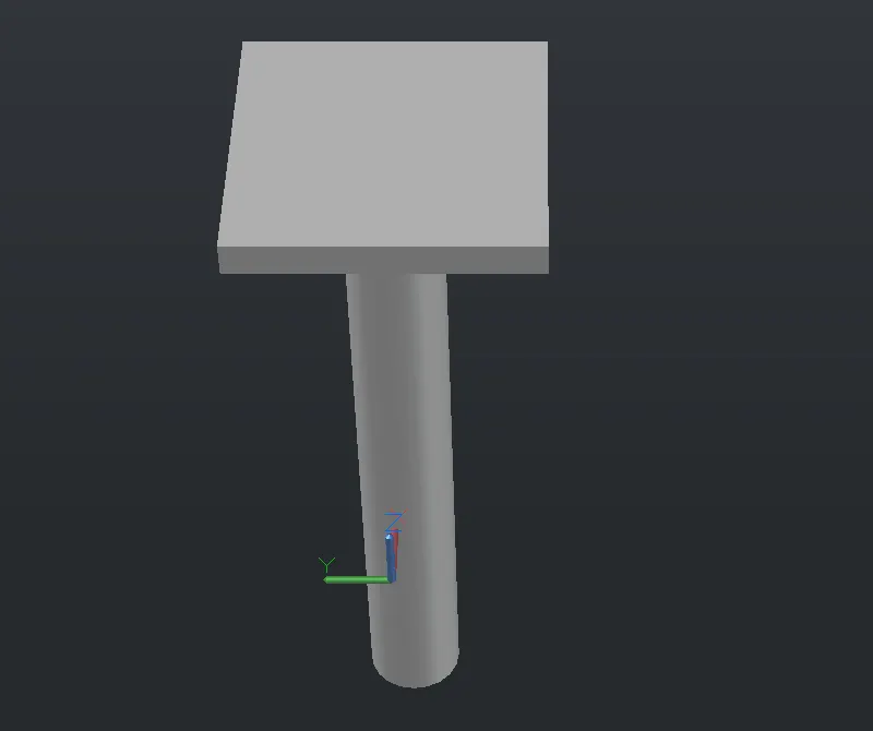
- Sweep this circle with the 10' line.
- region is created and extrude it.
Result:
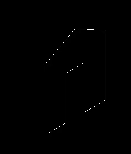
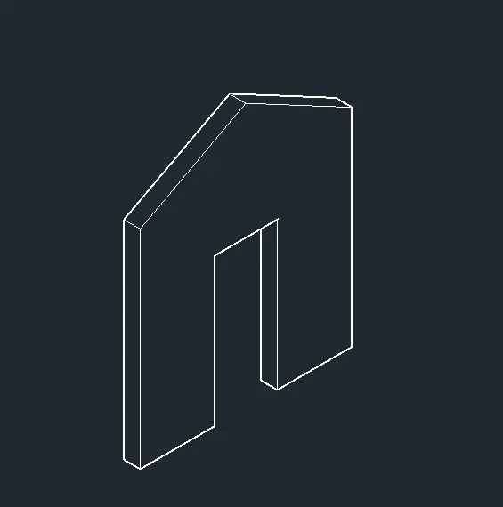
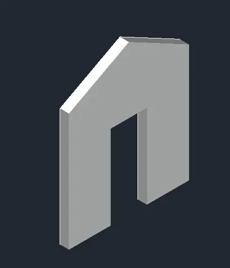
5. Creation of 3d model of wall
- Open the autocad new file slect the imperial.
- UN enter select the engineering and select the precision.
- From status bar select the workspace to 3d modelling.
- type ucs in command box enter change coordinate system.
- Type plan enter select the current ucs system.
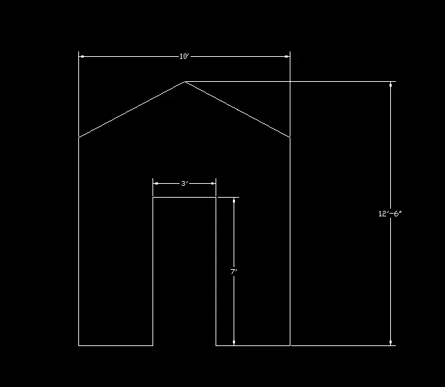
- select the line command draw the horizontal line of the length 10'
- From the centre of this line draw 7' vertical line. and offset it by a offset distance of 1'6" on either side join these two lines at the top.
- Erase the centre line.
- From the centre of bottom line draw the line of the length 12'6" vertically.
- From this point draw one line at 225 degree and another line at 315 degree.
- Draw the lines at the end points of the horizontal line till intersection of the inclined line.
- Trim the all unwanted lines.
- Type region select the whole object and it is converted into solid face.
- Extrude this solid face by 9" length.
Result: