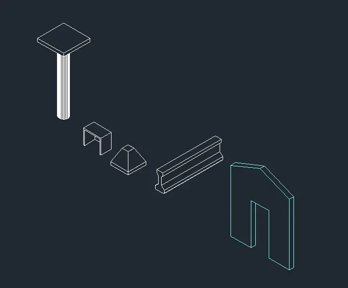
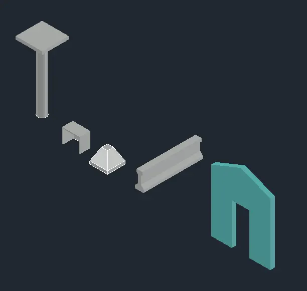
Creating various 3D Models like Furniture, Footing, Girder, Column drop with panel and Gable Wall in AutoCad
Creating various 3D Models like Furniture, Footing, Girder, Column drop with panel and Gable Wall in AutoCad
1. Create a 3D Furniture element as shown in the Figure. Assume dimensions which are missing.
AIM:
To draw the 3D Furniture element as shown in figure using AutoCAD software and explain the procedure step by step to obtain the result.
INTRODUCTION:
AutoCAD is a computer aided design software and drafting software application.
In this project, i have used important commands and settings like,
* 3D Basics and 3D Modelling setup
* Line - to create objects
* Region, Boundary - to create regions.
* Extrude - to extend the object created.
* Hide - to hide the extra wireframes and visualize a 3D model.
* 3DFace - to create 3D surface on the object
* various view types like Hidden, Shade, Isometric etc.. are used.
In the next step, the procedure is explained perfectly.
PROCEDURE:
- Open the AutoCAD software, start from scratch.
- Choose Metric system.
- Select 3D MODELLING space from the settings and start drawing.
- Set the units to Engineering and Limits to 0,0 to 1000',1000'.
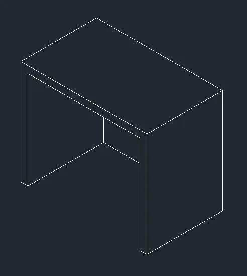
- Using the Line command, draw the frame of the furniture as shown in fig which is about Height 2'6", Breadth 3', Thickness 2" and Depth is assumed as 2'6".
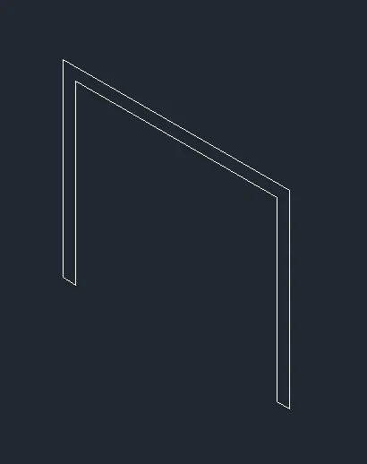
- Using REGION command, select the whole frame and convert it into a region.
- Then, using EXTRUDE command, select the whole frame and extend it to a depth of 2'6" as assumed before.
- Using Line command, join the bottom ends at the back face.
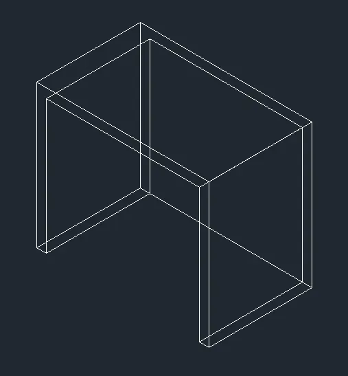
- Now, Use the HIDE command to hide the extra wireframes and visualize a 3D MODEL.
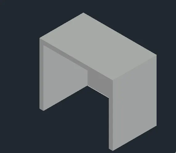
- Change the view to SHADED, to see the solid 3D Model.
RESULT:
2. Create the 3d Model of an Isolated footing as shown in Figure.
AIM:
To draw the 3D Model of an Isolated Footing as shown in figure using AutoCAD software and explain the procedure step by step to obtain the result.
INTRODUCTION:
AutoCAD is a computer aided design software and drafting software application.
In this project, i have used important commands and settings like,
* 3D Basics and 3D Modelling setup
* Line,Rectangle,Move - to create objects
* Region, Boundary - to create regions.
* Extrude - to extend the object created.
* Hide - to hide the extra wireframes and visualize a 3D model.
* 3DFace - to create 3D surface on the object
* various view types like Hidden, Shade, Isometric etc.. are used.
In the next step, the procedure is explained perfectly.
PROCEDURE:
- Open the AutoCAD software, start from scratch.
- Choose Metric system.
- Select 3D MODELLING space from the settings and start drawing.
- Set the units to Engineering and Limits to 0,0 to 1000',1000'.
- Using the Rectangle command, a square of 3' is drawn.
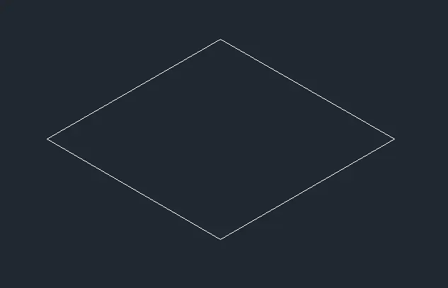
- Using the Copy command, the square is copied in the Z-Axis at a distance of 6".
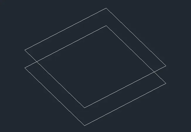
- Similarly, draw a square of sides 1' separately using the Rectangle command.
- Using Move command, move the smaller square with its center as base point and place it in the middle of the large upper square.
- Again using Move command, move the smaller square to a distance of 2' in the Z-Axis.

- Now, Using Line command, connect all the edges to form an 3D isolated footing.
- Using 3DFACE command, select all the faces (spaces with 4 corners) to create a 3D Surface..
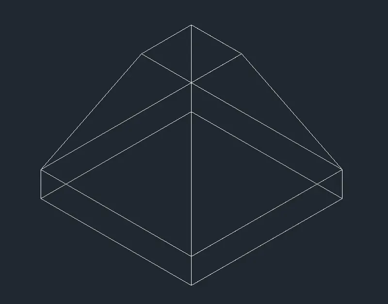
- HIDE command is used, to Hide the wireframes and visualize a 3D MODEL.
- The adjacent image is the top view of the footing.
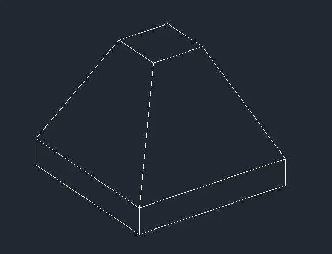
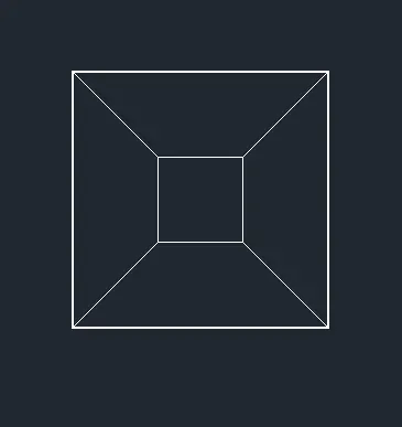
- View changed to SHADED, to see the Solid image of the Footing.
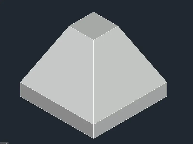
RESULT:
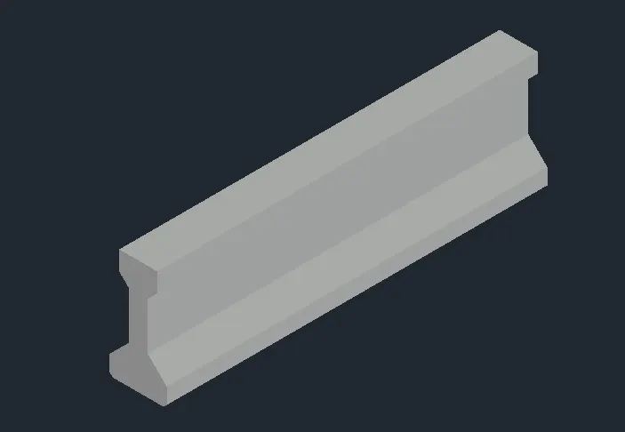
3. Create the 3D view of the AASTHO Type Girder.
AIM:
To Create the 3D view of the AASTHO Type Girder as shown in figure using AutoCAD software and explain the procedure step by step to obtain the result.
INTRODUCTION:
AutoCAD is a computer aided design software and drafting software application.
In this project, i have used important commands and settings like,
* 3D Basics and 3D Modelling setup
* Line, Chamfer - to create objects
* Region, Boundary - to create regions.
* Extrude - to extend the object created.
* Hide - to hide the extra wireframes and visualize a 3D model.
* 3DFace - to create 3D surface on the object
* various view types like Hidden, Shade, Isometric etc.. are used.
In the next step, the procedure is explained perfectly.
PROCEDURE:
- Open the AutoCAD software, start from scratch.
- Choose Metric system.
- Select 3D MODELLING space from the settings and start drawing.
- Set the units to Engineering and Limits to 0,0 to 1000',1000'.
- Using the Line command, top flange of 1', bottom flange of 1'6" and web of height 1'6" with 6" thickness is created.

- Using the CHAMFER command, both the flanges are connected to the web.
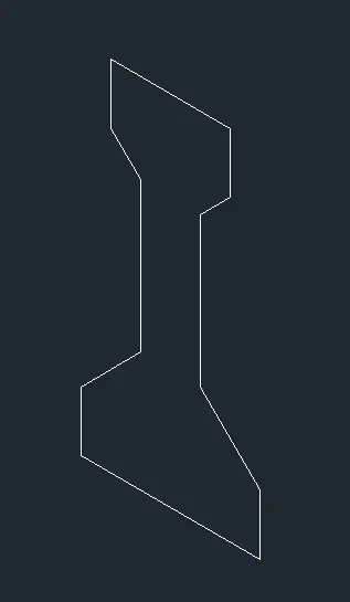
- Again CHAMFER command is used to chamfer the edges on the bottom flange.
- Now, using the REGION command, select the beam to make it a region.
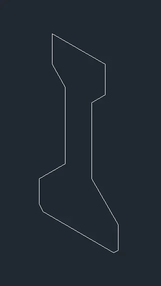
- Using the EXTRUDE command, select the beam and extend it to a distance of 10'.
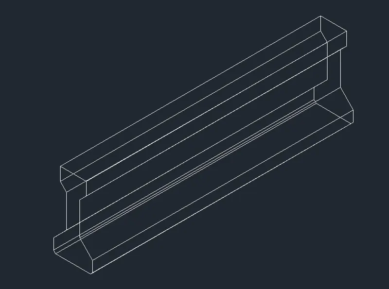
- Now, Use the HIDE command to hide the extra wireframes and visualize a 3D MODEL.
- The adjacent image is the top view of the beam.
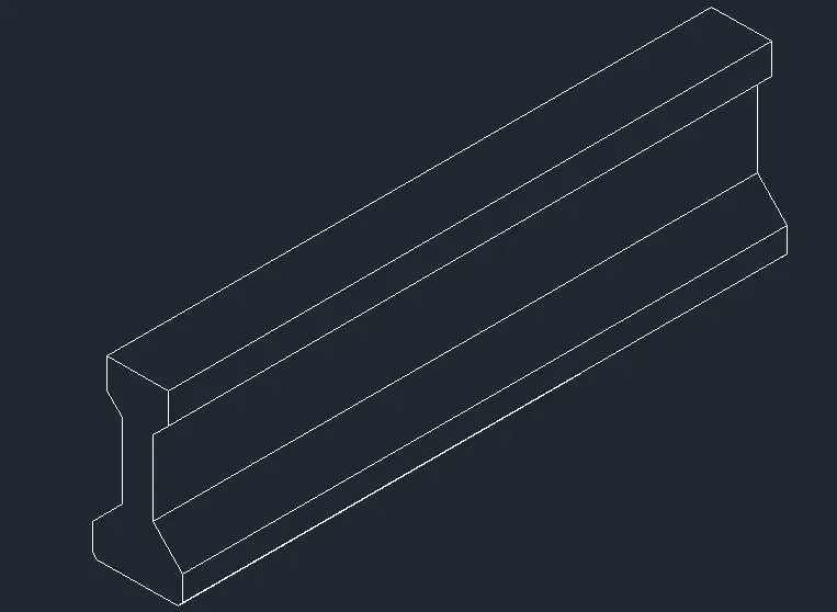
- Change the view to SHADED, to see the solid 3D Model.
RESULT:
4. Create a 3d Model of a drop column with panel as shown in section and isometric view.
AIM:
To Create the 3D Model of a drop column as shown in figure using AutoCAD software and explain the procedure step by step to obtain the result.
INTRODUCTION:
AutoCAD is a computer aided design software and drafting software application.
In this project, i have used important commands and settings like,
* 3D Basics and 3D Modelling setup
* Line, Rectangle, Circle - to create objects.
* Cone - (Tapered Cone) is used here.
* Extrude - to extend the object created.
* SurfTAB1 - to set the number of lines between the objects.
* RULESURF - to include the lines of SurfTAB1 between 2 objects.
* Hide - to hide the extra wireframes and visualize a 3D model.
* 3DFace - to create 3D surface on the object
* various view types like Hidden, Shade, Isometric etc.. are used.
In the next step, the procedure is explained perfectly.
PROCEDURE:
- Open the AutoCAD software, start from scratch.
- Choose Metric system.
- Select 3D MODELLING space from the settings and start drawing.
- Set the units to Engineering and Limits to 0,0 to 1000',1000'.
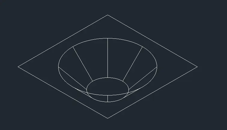
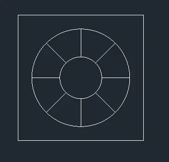
- Using the Rectangle command, a Square of 4'6" is drawn.
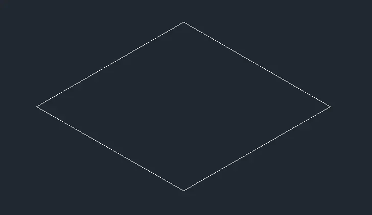
- Using Circle command, a circle of diameter 1'6" is drawn with the center of the square as its center.
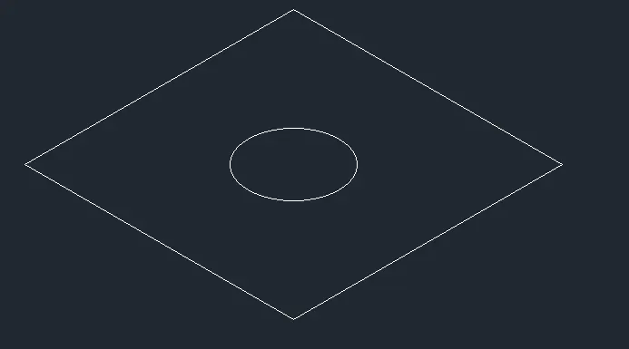
- Now, using Move command, the circle is moved down to 1' in the negative Z-Axis.
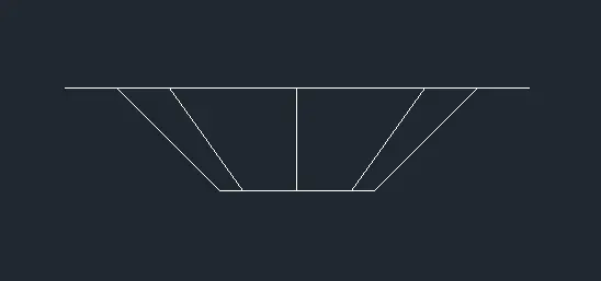
- The adjacent image shows the front view of the drawing so far.
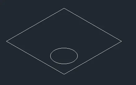
- Using the center of the square as the base point, create a TAPERED CONE of base radius 3'6", top radius as 1'6" and height as 1' in the negative Z-Axis.
- The following images shows the front view and the top view of the drawing so far.
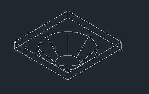
- Using the EXTRUDE command, select the square and extend it to a distance of 6".
- Now, create 2 circles of diameter 1'6" separately with a vertical distance of 10' between them.
- Using the SurfTAB1 command, set the number of lines to 50.
- Now, using the RULESURF command, select the 2 circles to create a ruled surface as shown below.


- Using Move command, move the ruled surface column created and place it at the end of tapered cone with center axis of 2 objects be the same.
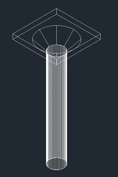
- Use the HIDE command to hide the extra wireframes and visualize a 3D MODEL.
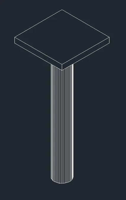
- Change the view to SHADED, to see the solid 3D Model.
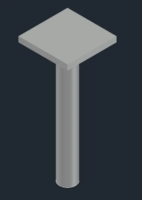
RESULT:
5. Create the 3d model of a wall as shown in Figure. Consider wall thickness as 9”.
AIM:
To Create the 3D Model of a Wall as shown in figure using AutoCAD software and explain the procedure step by step to obtain the result.
INTRODUCTION:
AutoCAD is a computer aided design software and drafting software application.
In this project, i have used important commands and settings like,
* 3D Basics and 3D Modelling setup
* Line, Rectangle - to create objects.
* Region, Boundary - to create regions.
* Extrude - to extend the object created.
* SUBTRACT - to subtract the door space from the wall.
* Hide - to hide the extra wireframes and visualize a 3D model.
* various view types like Hidden, Shade, Isometric etc.. are used.
In the next step, the procedure is explained perfectly.
PROCEDURE:
- Open the AutoCAD software, start from scratch.
- Choose Metric system.
- Select 3D MODELLING space from the settings and start drawing.
- Set the units to Engineering and Limits to 0,0 to 1000',1000'.
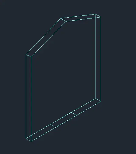
- Using the Line command, create the wall surface with breadth having 10' and center height as 12'6" and assume the height at edges as 10'6" and join it with the center height.
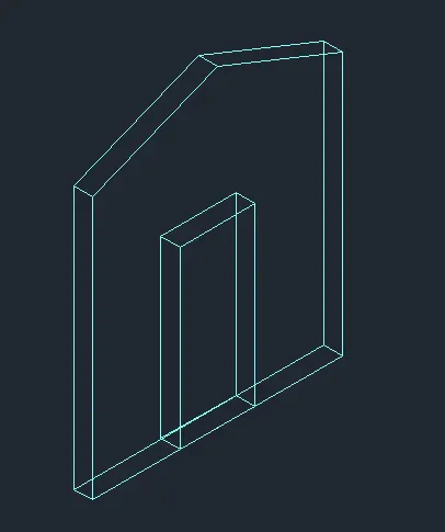
- Also, draw a rectangle of 3' breadth and 9" thickness at the center of the wall as shown.
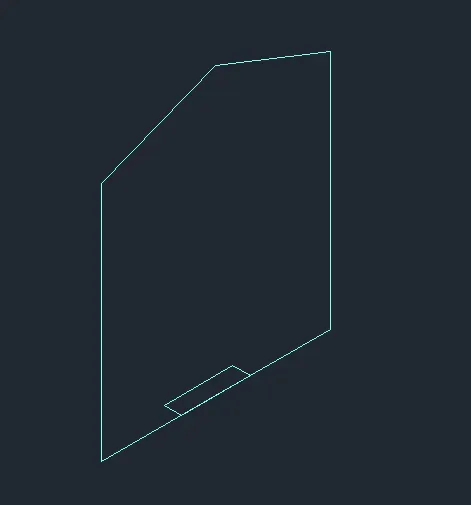
- Using REGION command, select the wall and create a region.
- After creating the region, Using EXTRUDE command, select the Wall and extend it to a thickness of 9".
- Again, using EXTRUDE command, extend the Door rectangle at the bottom to a height of 7'.
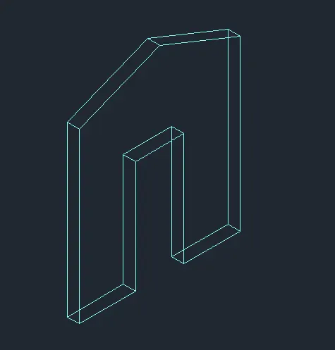
- Now, using SUBTRACT command, subtract the door from the wall.
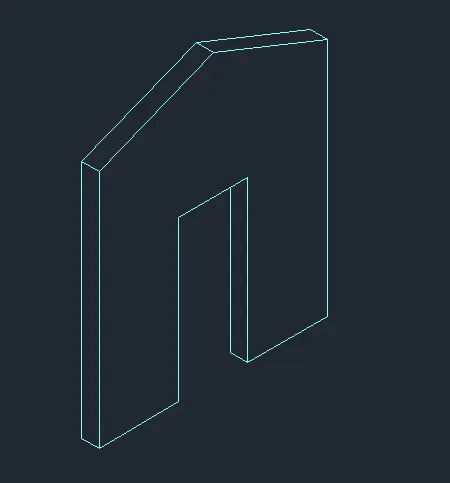
- Use the HIDE command to hide the extra wireframes and visualize a 3D MODEL.
- Change the view to SHADED, to see the solid 3D Model.

RESULT:
ADDITIONAL IMAGE: