Creating Levels, Grids, Layout and model elements for a residential unit using REVIT
Name: Allan Bryan Jayson Cruz
Course: Master’s Certification Program in High-Rise Building Design & Analysis
Date: December 20, 2021
Challenge 2_Creating Levels, Grids, Layout and model elements for a residential unit using REVIT
********************************************************
1. Aim & Introduction
***************
Aim
This challenge aims to allow the student to utilize and understand the Revit Software tools and parameters. It familiarizes the student to the Revit modeling and drafting that includes the creation of all elements in a sketch such as Grid Lines, Levels, Architectural Elements, Structural Elements, and Structural Parameters.
Introduction
Revit is a building information modelling software that allows the user to create and design a 3D model building structure. It is an architectural, structural, and mechanical software where the user can provide 3D illustration of the building as well as its design.
********************************************************
2. Detail Procedure
***************
1) What is BIM? Summarize the features of BIM and benefits of using BIM over 2D CAD tools.
BIM stands for Building Information Modeling. It is a a process of creating and managing information for a built asset. It is based on an intelligent model and is enabled by a cloud platform. BIM integrates multi-disciplinery data which is structured inside the model to produce a digital representation of an asset across its lifestyle. This process includes planning, designing, constrution and operation.
BIM has two core concepts which are Coordintaion and Computation. Coordintation describes the coordination of multiple-disciplines across the project. This allows multiple users to work on a project under one model where faster, precise, and efficient modelling and designing procedures are achieved. The next is Computation. Computation describes the ability of the software to design the modeled structure in the likes of Material Scheduling, Quantity scheduling, Energy analysis evaluation, and Structural analysis required in each descipline.
BIM allows real time or instant revision compared to 2D CAD tools. It has the ability to change any aspect in the model while reflecting it instantly. When using 2D CAD tools, once changes are required, multiple plans, elevations, sections, or details are required to be revised while in BIM, these changes can be made in a single view and can be reflected on all other views instantly. These minimizes the time required to create the whole project.
***************
2) Understand the concept of Categories, Families, Elements, Instances in Revit. Go to Insert Tab, choose a category. Pick a family and element. Understand the instances and insert it to Revit model.
Introduction:
Categories, Families, Elements and Instances are Revit database components that allows the user to insert different details to the project.
Categories - The are properties in Revit that are already predefined by the software. Examples are Doors, Window, and Walls. Once these items are modeled, their properties or materials defined by the user is classified as categories.
Family - These are groups of elements that have the same properties. Under a single category, a number of elements are presents representing a certain item. These elements are grouped and are classified as a family.
Elements - Elements are what compose a family. These are items that contains an individual property. When an item like a door under a family is identified singularly with its own property, it is classified as an element.
Instances - These are individual properties of an element such as height, width, or length. Each element instances can be changed indivually or by family.
PROCEDURE:
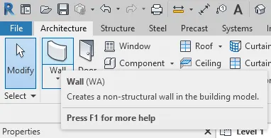
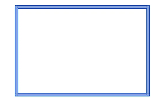
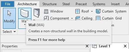
- Under the Architecture tab, select a category. Example is Wall. Create a wall model on the interface.
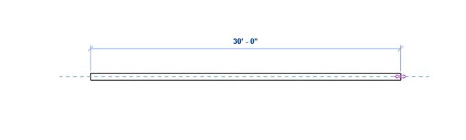
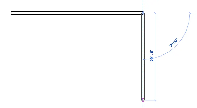
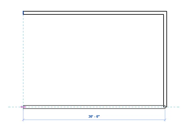
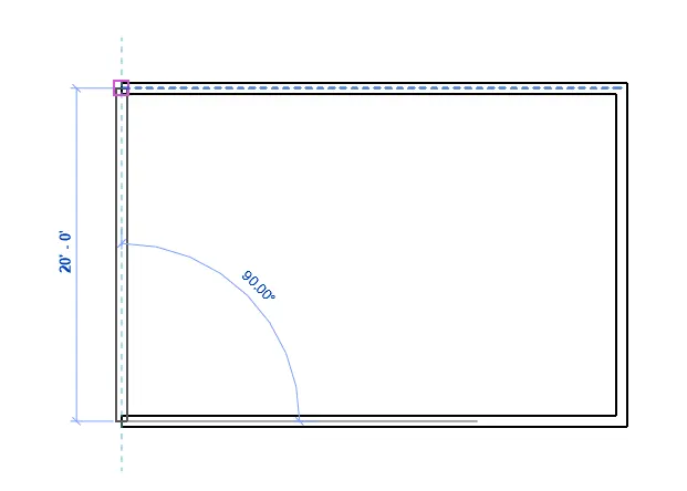
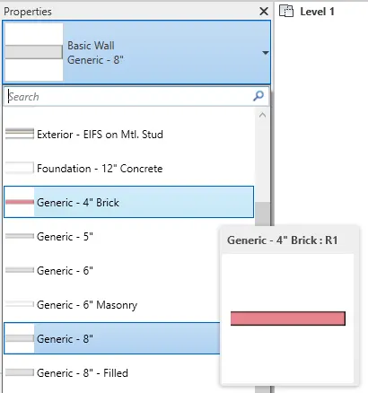
- To select a family and element, select the created category. In the properties tab, drag down the shown family and select the desired element under a desired family.
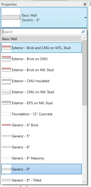
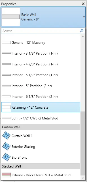
- Basic Wall, Curtain Wall and Stacked Wall fall under Family and the others are elements.
- Once the family and element are decided, the model will change as described.
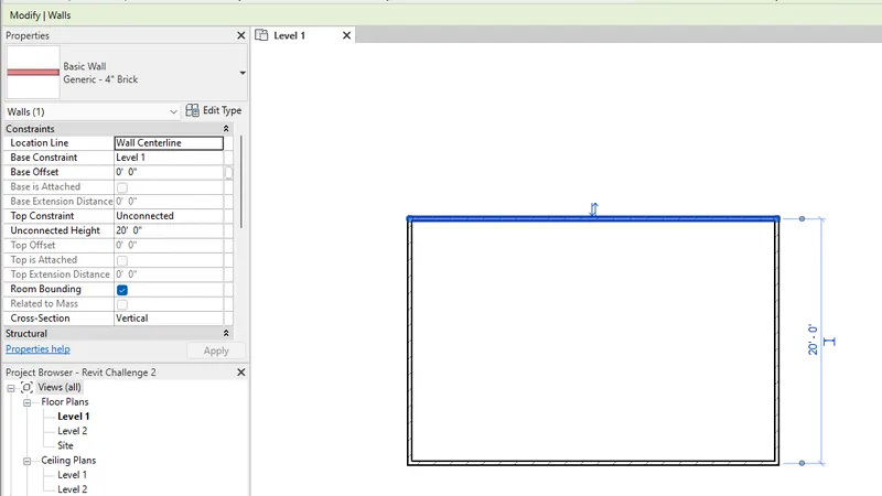
- Check and decide the instances. Again, select the category and see the instances under the properties tab.
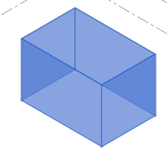
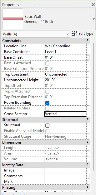
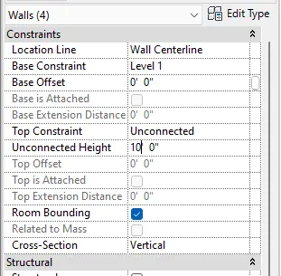
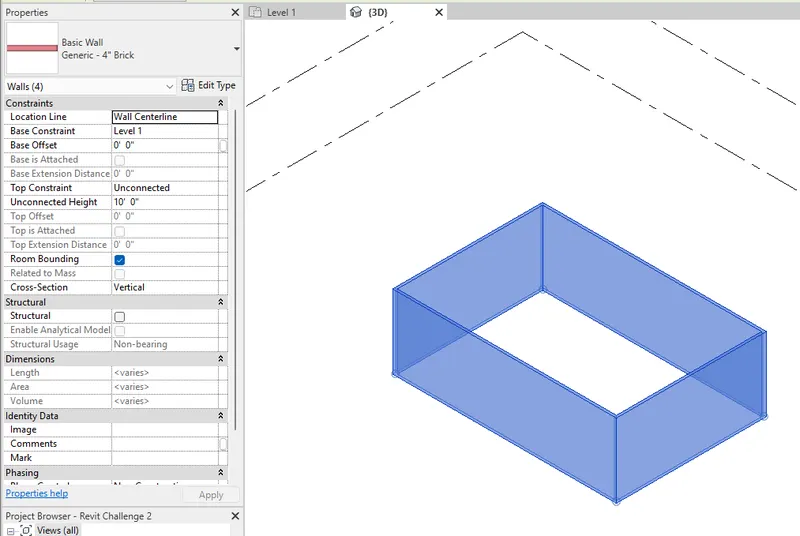
- An example is by changing the Unconnected Height instance, once revised or changed, the model instance will change appropriately.
***************
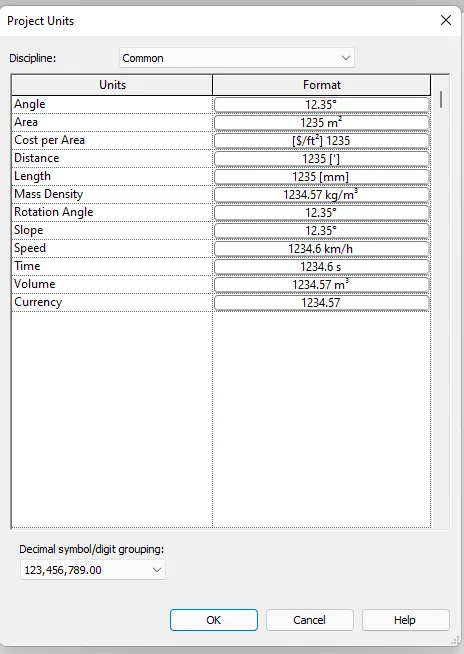
3) Setting up a Project – Open a project file with architectural template. Save the file with appropriate name. Set up the project units to Imperial / Metric based on your convenience of modelling. Complete the project information under Manage tab. Set up the maximum backups for project file to 3.
PROCEDURE:
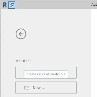
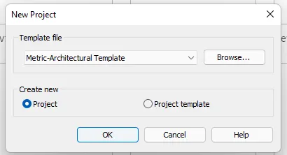
- On the home page, select new and set Template file into Architectural Template.
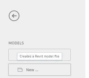
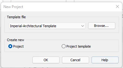
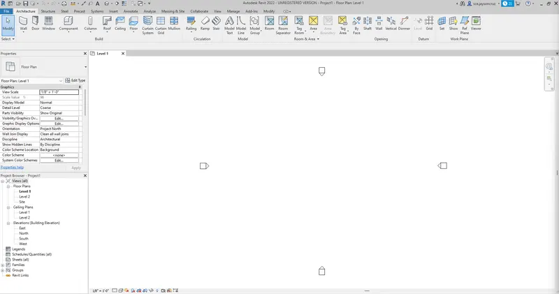
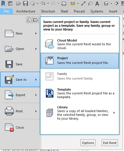
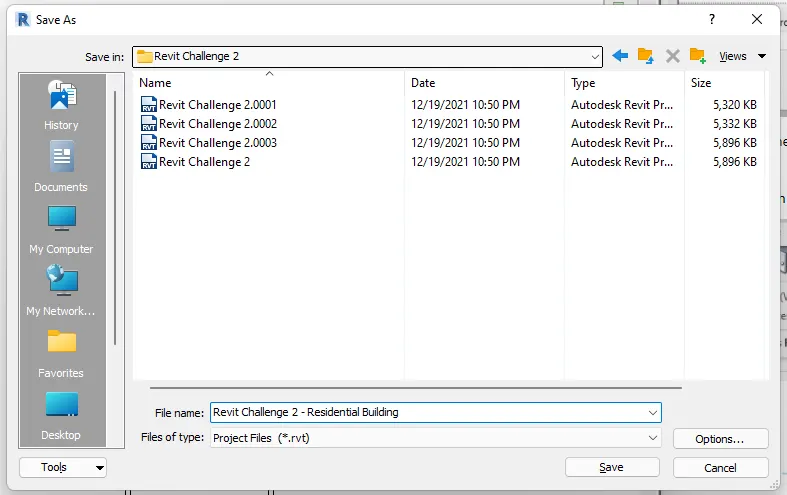
- Save the file with appropriate name. Go to file menu and click Save us.
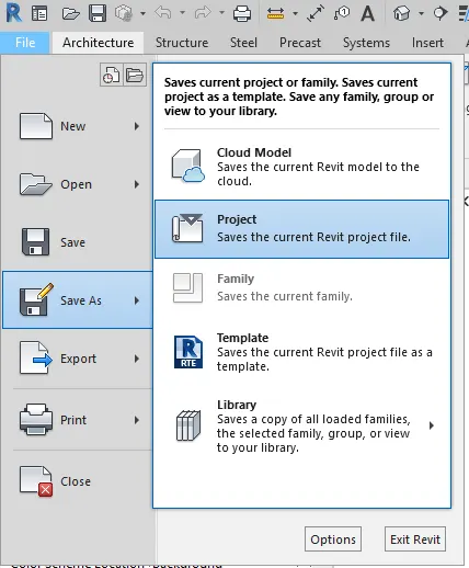
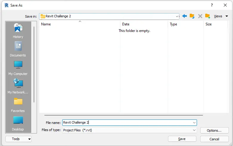
- Now setup the project units of measurement under the Manage Tab. Select the discipline and set the units accordingly.

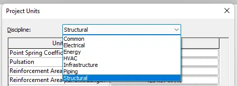
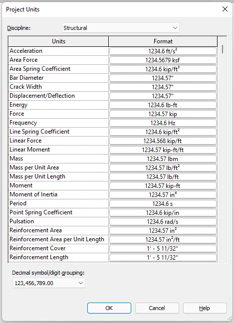
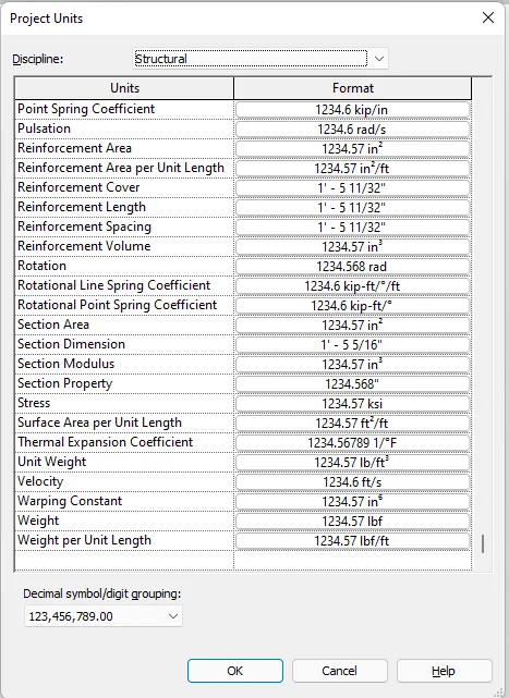
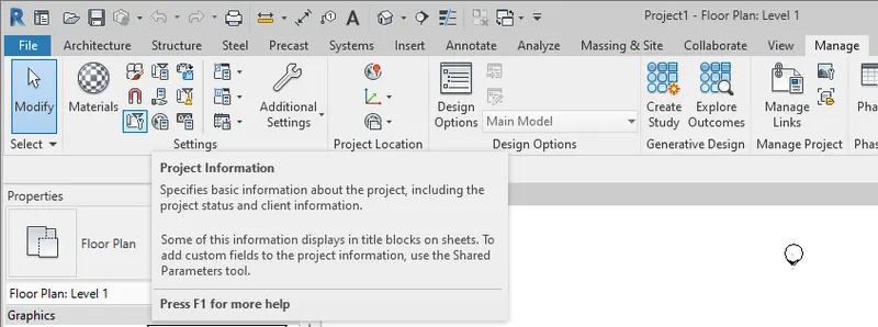
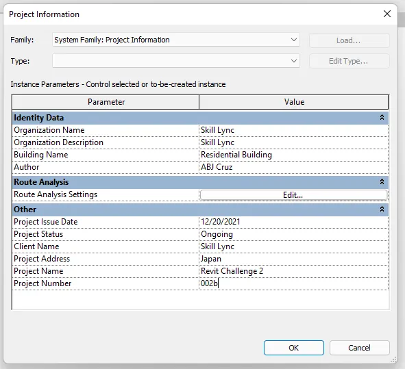
- Now setup the required project infomration under the Manage Tab --> Project Information.
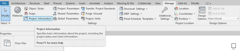
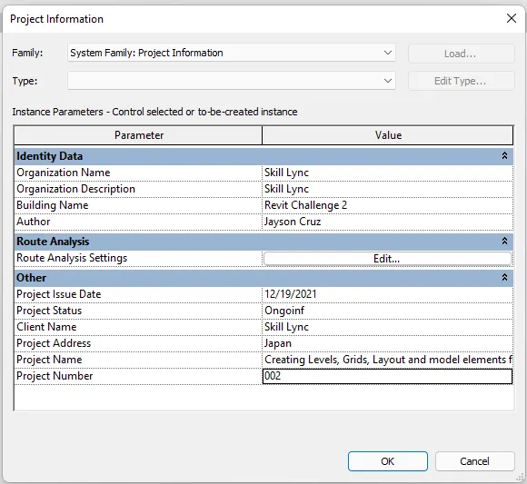
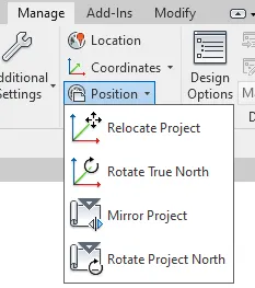
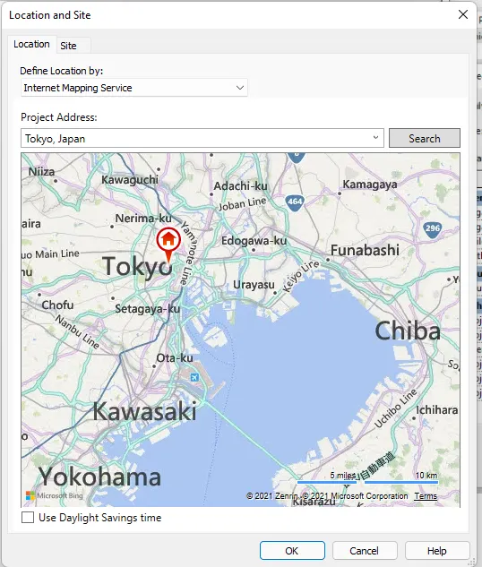
- You can also setup the project location, coordinates and position under the management tab.
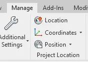
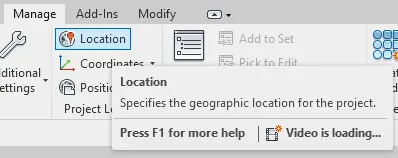
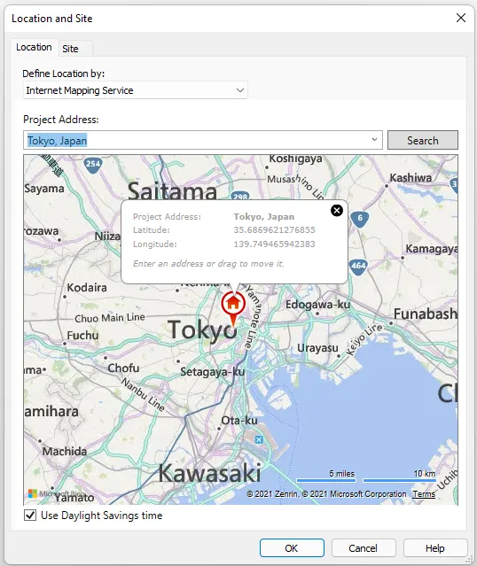
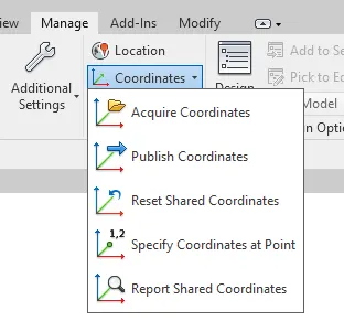
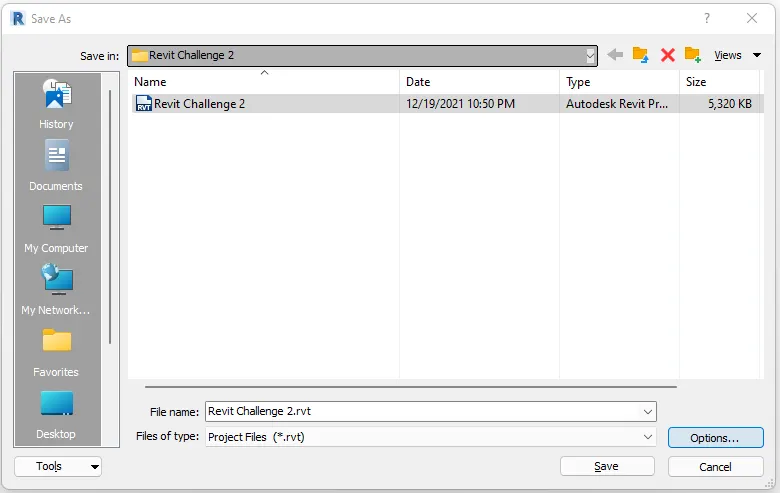
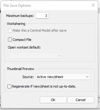
- Now, set up the maximum backups for project file to 3. Go to File menu --> Save as. In the Save as window, select Options. Make sure the value under Maximum Backups is equal to three (3).
***************
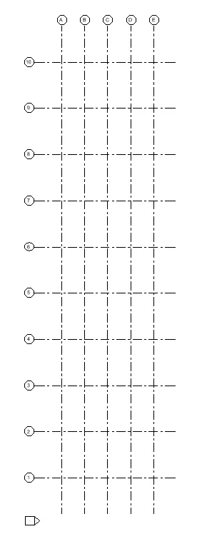
4) Understand the concept of Levels and Grids. Follow the naming and conventions. Create the following Levels: (Convert to metric equivalents if metric is your units)
Ground Floor @ 0’
First Floor @ 10’
Second Floor @ 20’
Roof @ 30’
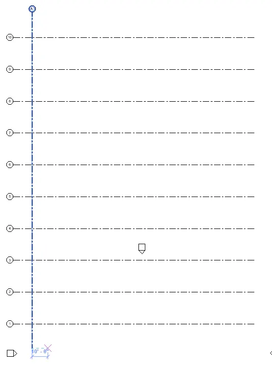
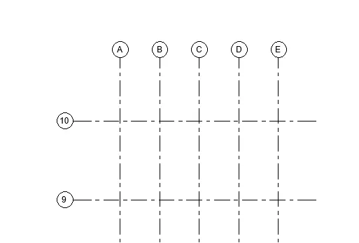
Grids Transverse Grids A, B, C, D, E @ 10’ spacing
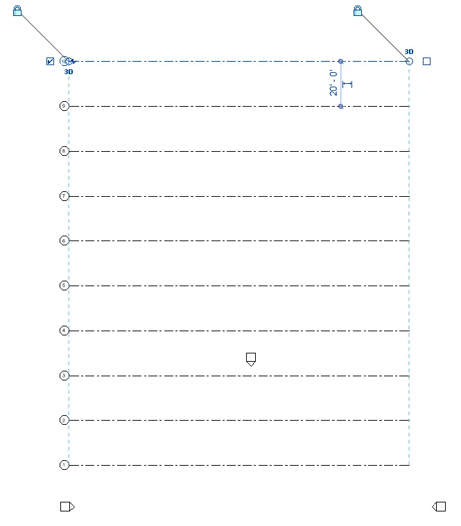
Longitudinal Grids from 1 to 10 @ 20’ spacing
PROCEDURE:
- To create levels, first go to the elevation views. Elevation views consist of East, North, South, and West.
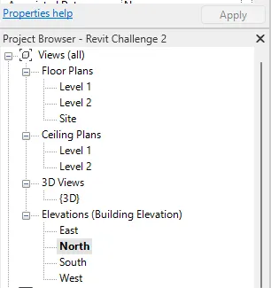
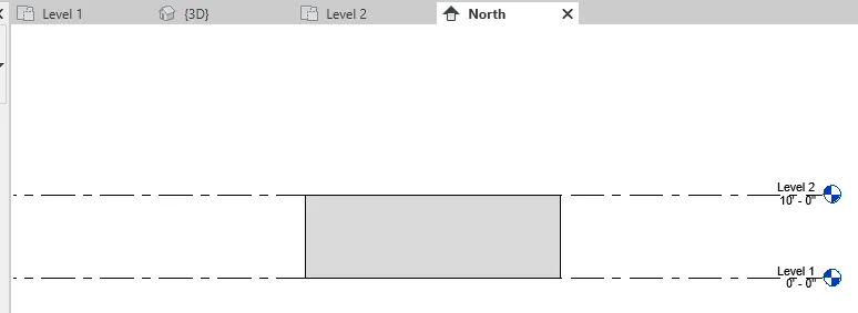
- First add the designated levels. Level 1 and Level 2 are already assigned, you can change the name of the levels by clicking on the texts.
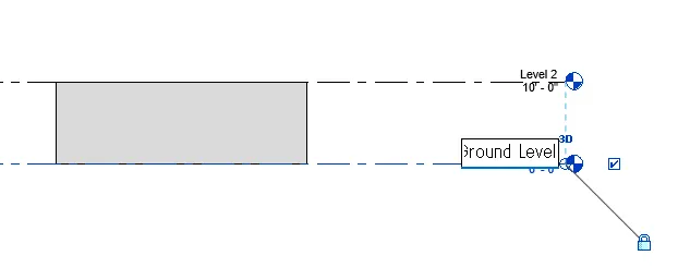
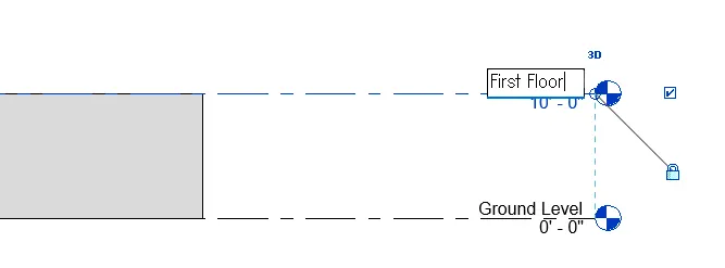
- To add the other levels, go to the Architecture Tab. Under the Architecture tab, select Level and sketch on the model to draw. Identify the levels accordingly.

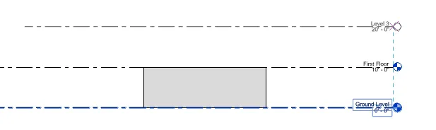
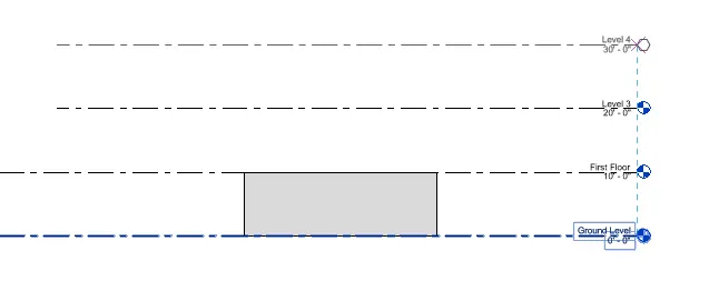
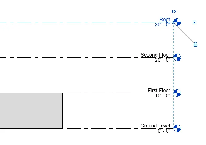
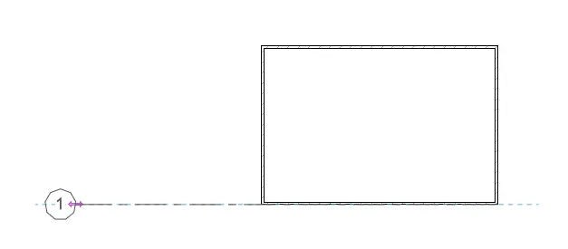
- When the levels are created, proceed with the Grid Lines. Go to Plan view and create the grids which is located under the same tab.
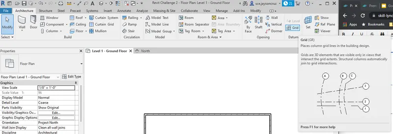
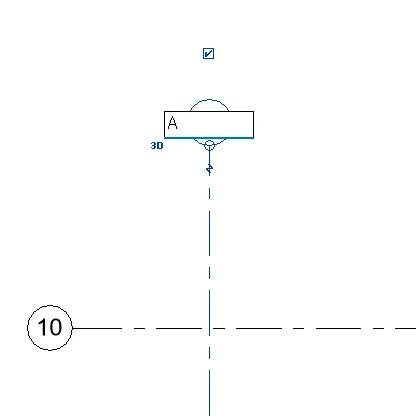
- Do the same procedure for the transverse direction. Change the letter of the first grid tp control the markings.
***************
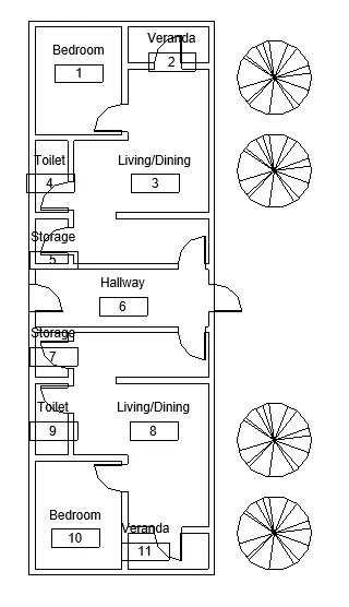
5) 3D modelling of residential unit – From looking at your house / or a place you aspire. Create a conceptual layout of the residential unit. You can measure using a tape or you can access your residential plan to create a similar layout.
PROCEDURE:
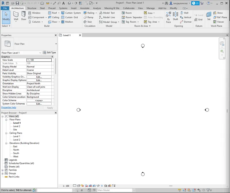
- First create a new project.
- Add the project information under the management tab.
- Now save the project.
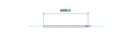
- Proceed with the modeling under the Architecture Tab.
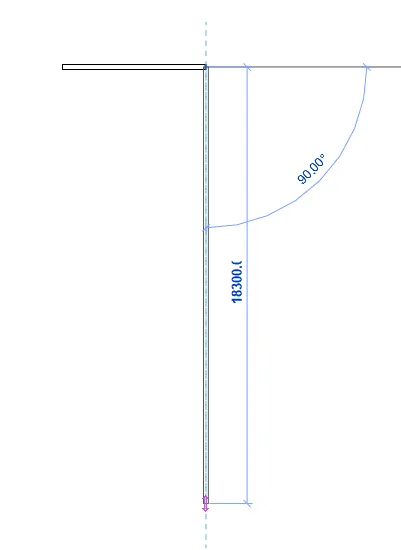
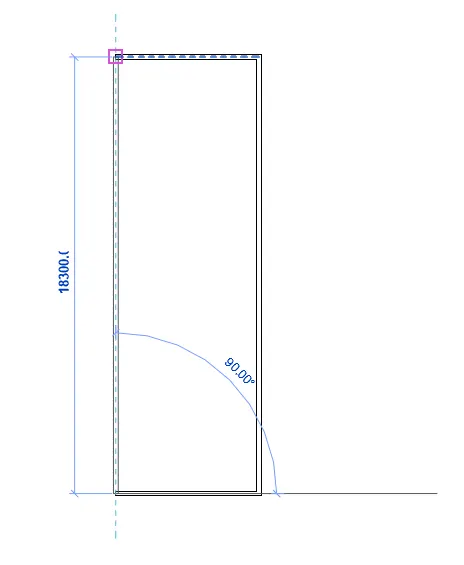
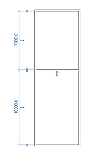
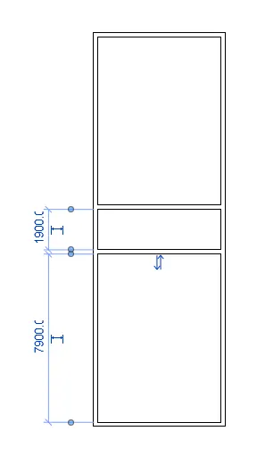
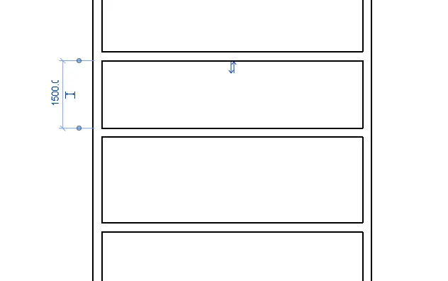
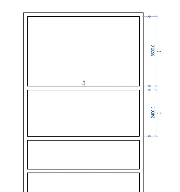
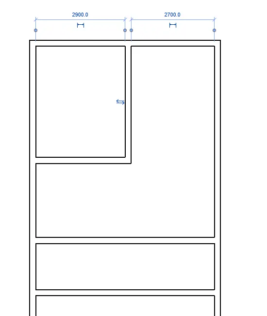
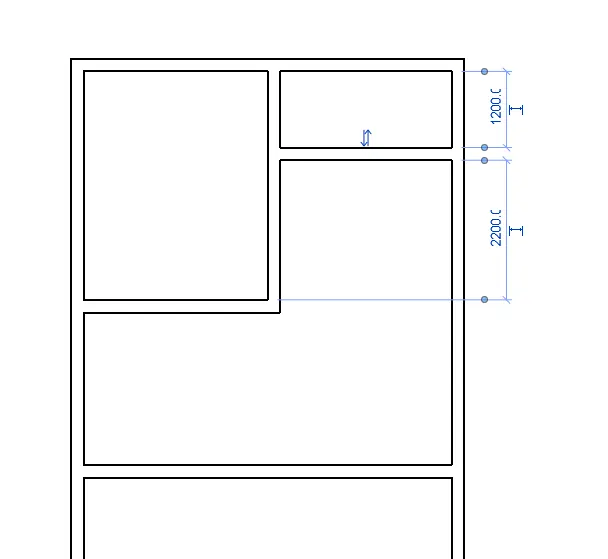
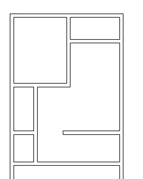
- Do the same layout on the other side.
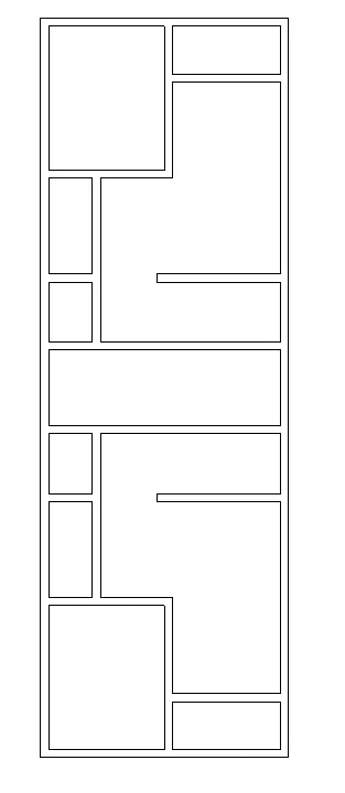
- Add the door categories.
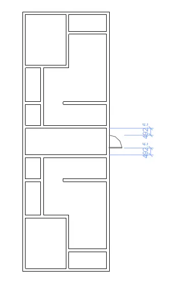
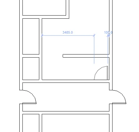
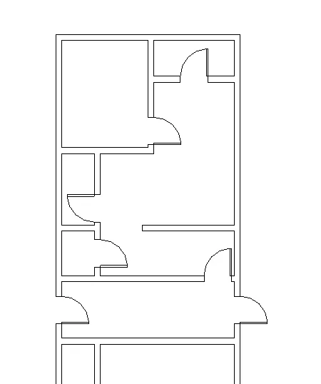
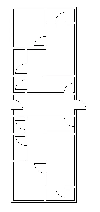
- The residential plan is created.
***************
6) In the layout created draft the level of details you are planning to include – Dimensions of room, components you plan to add in the residential unit.
PROCEDURE:
- Add the room dimension and components.
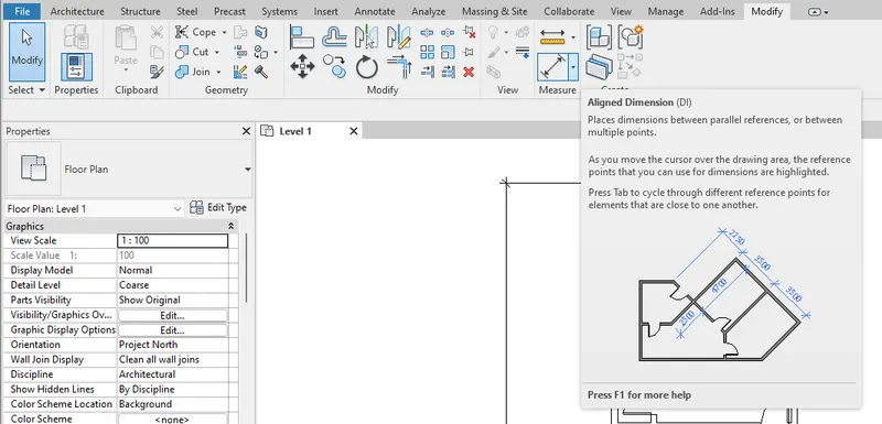
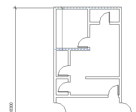
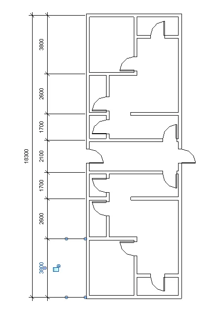
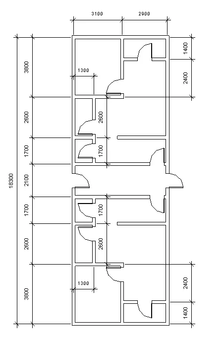
- Add the floor on level one.
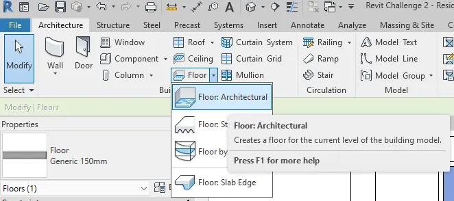
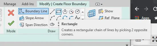
- Set the boundary using the rectangle option.
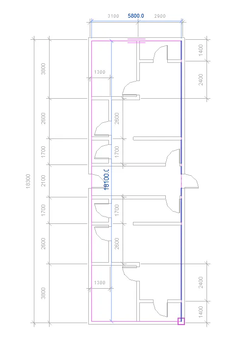
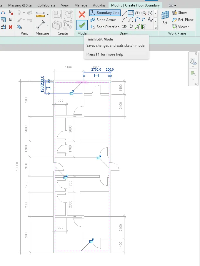
- Select Finish Edit mode to create the floor.
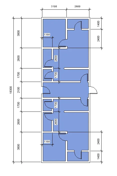
- You can describe the floor level in the properties tab.
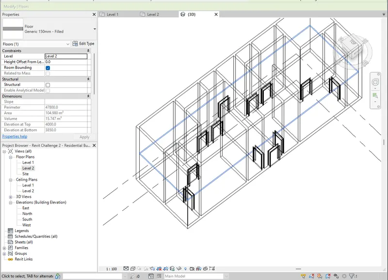
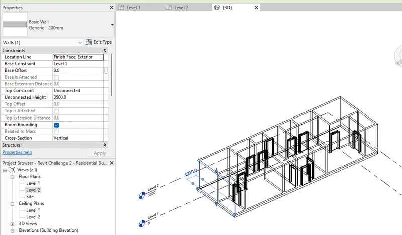
- Move the floor to Level 1 and adjust the wall height to 3500.
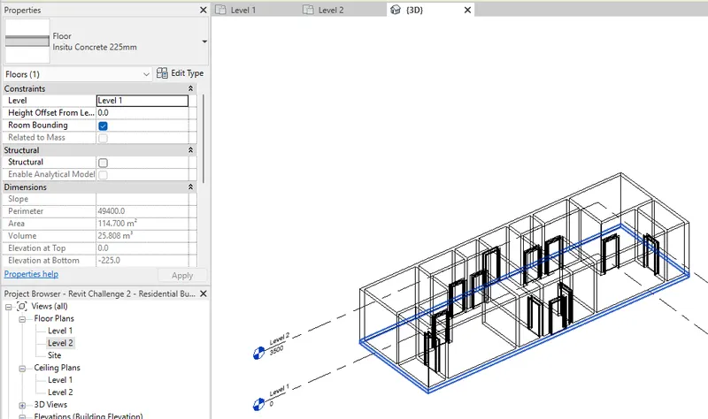
- Add the Roof to finish. Make sure to put it on level 2.
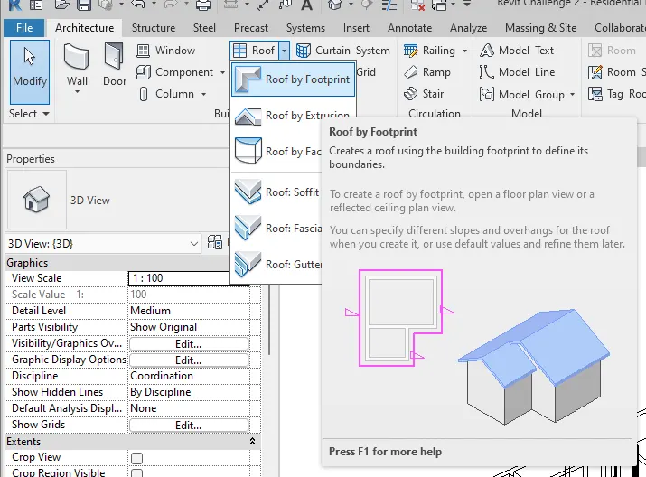
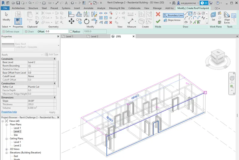
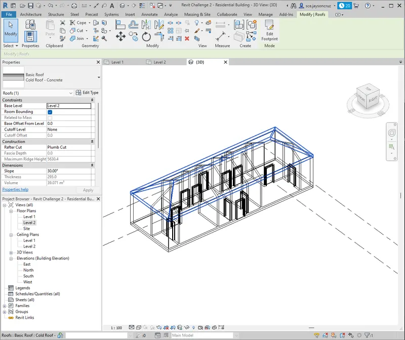
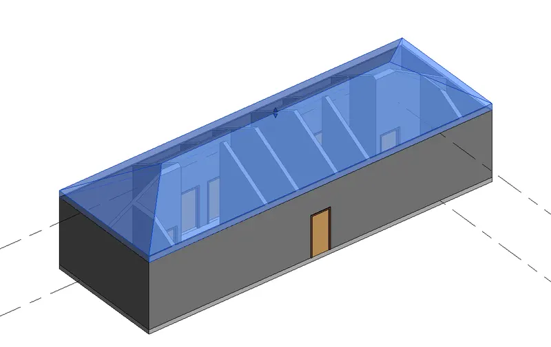
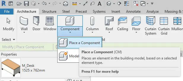
- Add Components as desired.
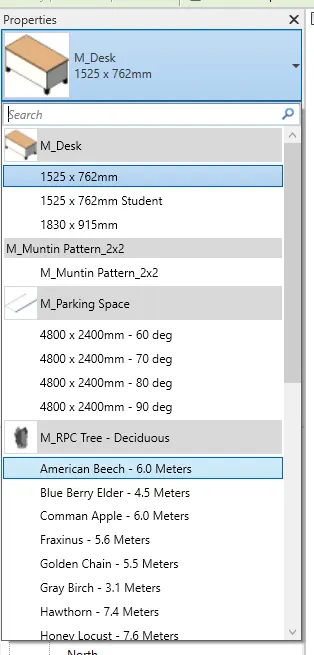
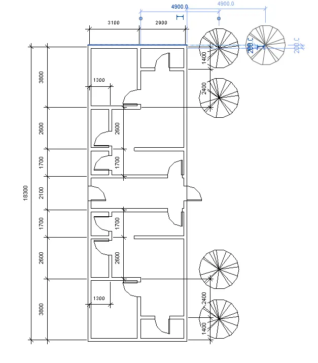
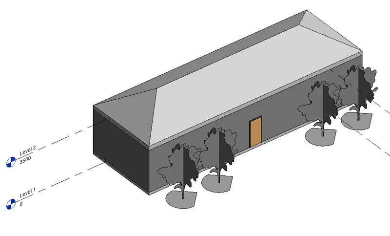
- Instead of dimensions, once can add room tags to show room names and floor area.
- Set up room using the room tool.

- Pick the spaces as desired.
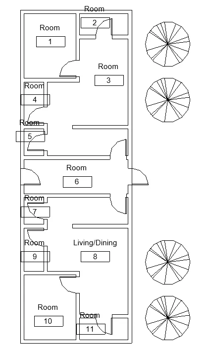
- Rename room as desired.
***************
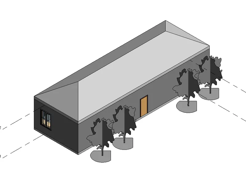
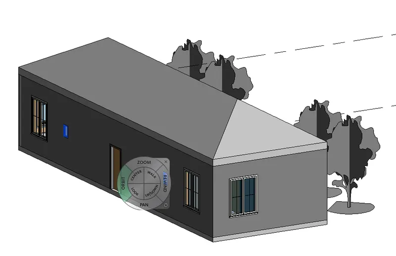
7) Identify the residential model elements such as Door, Windows, Tables, Chair, Couch, Bed, Lamps from the library and insert them to the model . Save the project for use for Assignment 3.
PROCEDURE:
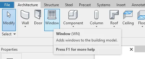
- Add the windows using the window tool under Architecture tab.
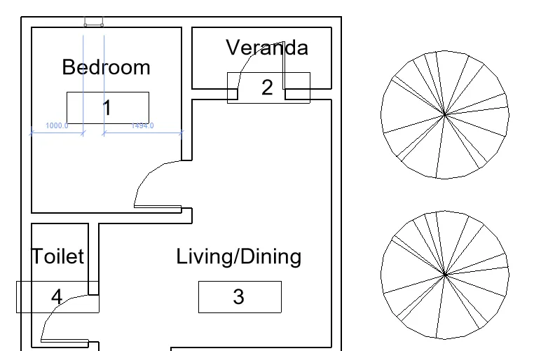
- Select the location of the windows.
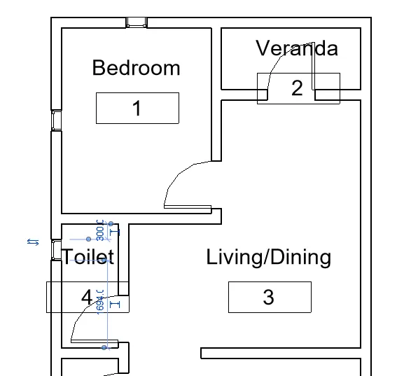
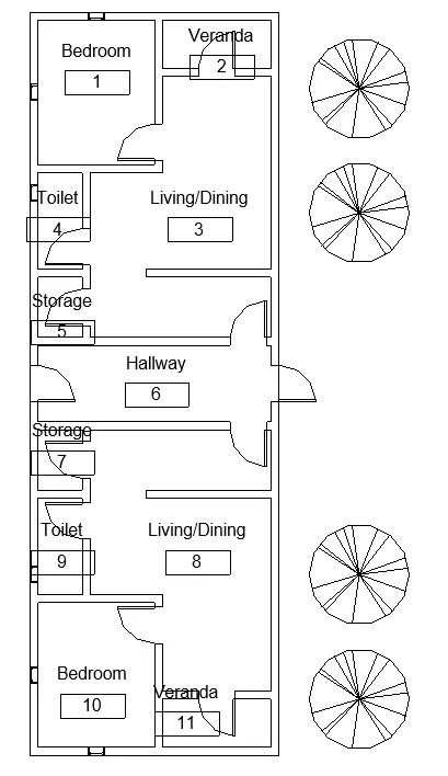
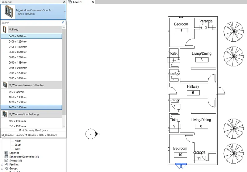
- Change the window element by clicking the element and selecting the element type on the properties tab.
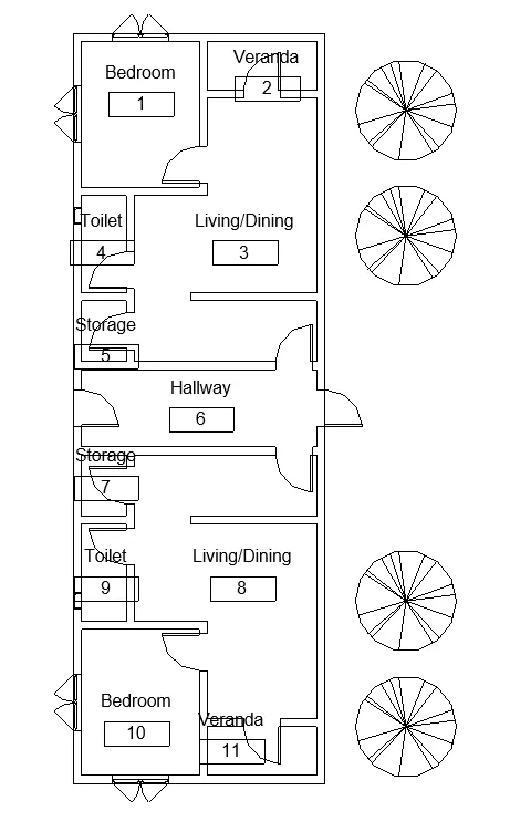
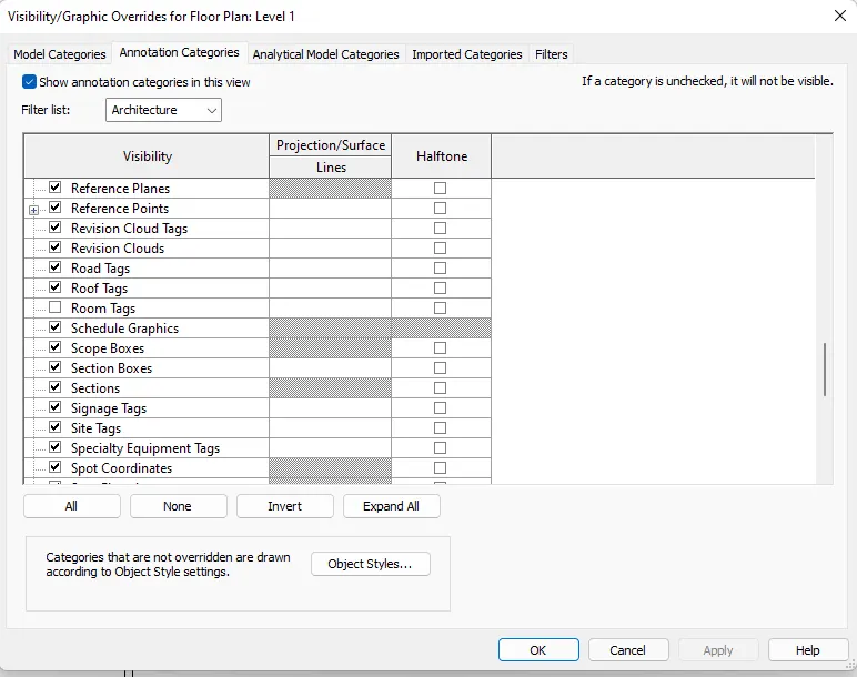
- Hide the room tags and add the desired architectural elements.
- Load the architectural families to add the architectural elements. Go to Architectural tab - Components - Load Family.

- If there are no families given, you need to download the pack. Once the pack is downloaded, you can apply the components as below.
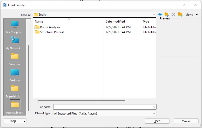
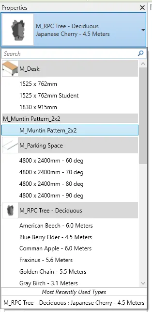
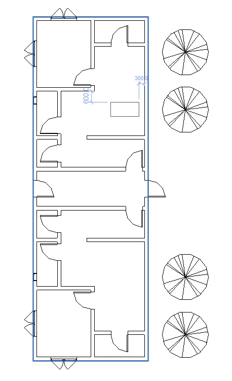
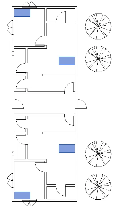
- To add these comonents, select the desired element in the properties tab and apply to model.
********************************************************
3. Conclusion
***************
The Revit software is a BIM software that allows the user to model, change, and design in a real time environment. It give the impression of 3D modeling by the use of categories, family, elements and instances. Revit provides different tools related to multiple disciplines that allows each user from different fields to work in a single environment.
Revit, or the BIM software, has benefits like faster modeling, easier revising, and much more. These gives it an advantage to 2D drafting tools where changes takes time to apply. Moreover, Revit provides a wide range database containing the components used in creating a project.