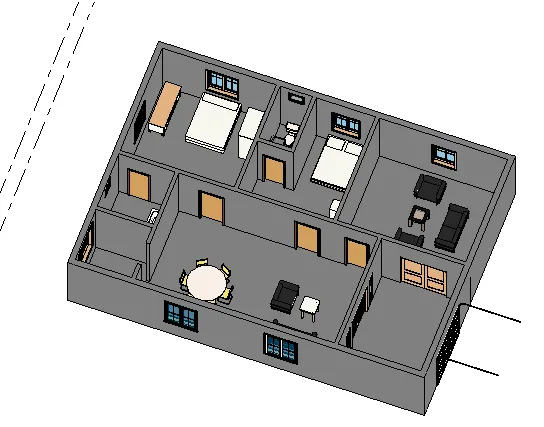
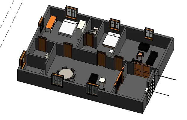
Creating Levels, Grids, Layout and model elements for a residential unit using REVIT
1): What is BIM? Summarize the features of BIM and benefits of using BIM over 2D CAD tools.
A): Building information modeling (BIM):
- As the name suggest the most common feature is information. BIM is a concept that was created by Autodesk. The work process of BIM is to create and manage all the information surrounding design assets ensuring improved collaboration, shared data, and project delivery that is on time and on budget.
Features:
BIM is divided into to core concepts
- Coordinate:
- Revit help in coordinate of multiple features
- Such as Revit offers in coordination of multiple project in Architectural, Structural, Mechanical, etc. In a single project as independent drawing.
- Computation:
- It help to create material schedule, quantity schedules, and performing energy analysis in Revit.
BIM is a feature with the achieving coordination and performing computation we ca as add information and as much as details to our project .
Benefits of using BIM over 2D CAD tools:
- A BIM model will allow you to prefabricate important components ahead of time.
- BIM offers a more complete representation of a building's design
- You can provide much more to your clients using BIM than you could with CAD.
2):
Aim: To understand the concept of Categories, Families, Elements, Instances in Revit
Introduction: To understand the concept of Categories, Families, Elements, Instances in Revit
Procedure:
Step1:
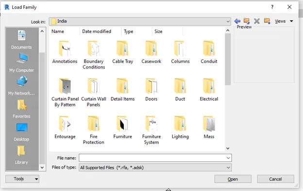
- From the tool bar select the insert click on the load family
- A dialogue box appears with the type of category
Step2:
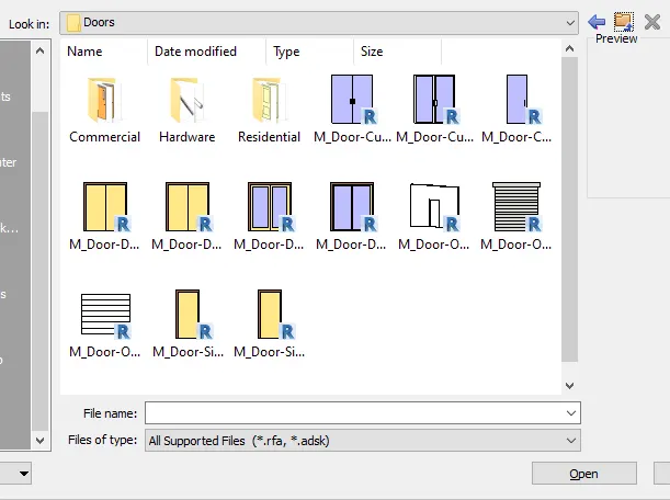
- Select the any type for example select the door
- Now a door is family with in the different type of and different size of door are available are consider as single elements
3):
Aim: To Setting up a Project. And complete the project information under Manage tab. Set up the maximum backups for project file to 3.
Introduction: To Setting up a Project. And complete the project information under Manage tab. Set up the maximum backups for project file to 3. In Revit.
Procedure:
Step1:
- Open the Revit from the welcome page left side select the new project
- From the template file select Architectural imperial template
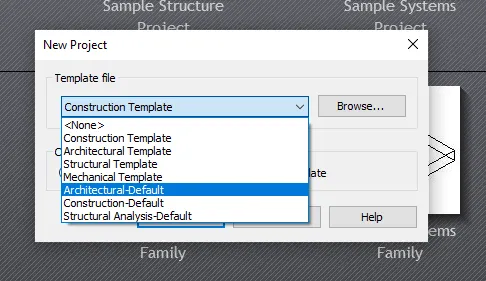
Step2:
- Now go to the manage tool
- Click on the project information icon
- Project information dialogue box will appears
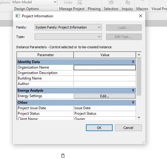
Step3:
- Give the project name, project status, etc. fill all the information and details of the project as shown.
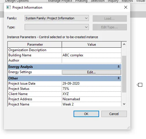
Step4;
- Now from the menu bar click on the file and go the save as project
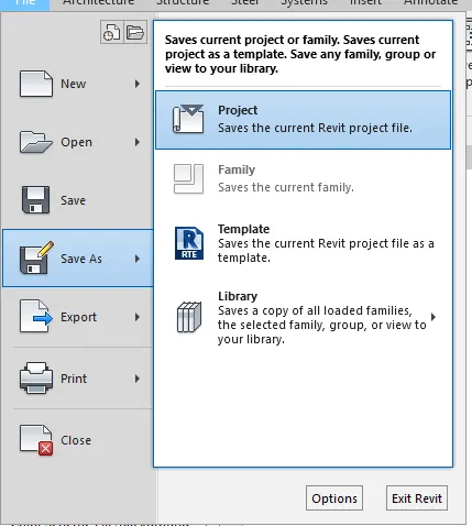
Step5:
- Give name of the project and location to save the file
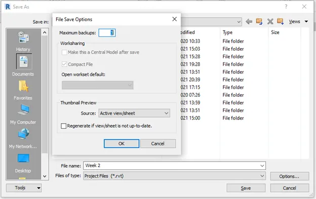
- Now click on the option to give the max backups is given as 3 then click on the save
Result:
- The above created Revit file is saved with the project name, project details, with the max backup of 3 at the given location.
4):
Aim: To understand the concept of Levels and Grids.
Introduction: To understand the concept of Levels and Grids. By using Revit.
Procedure:
Step1:
- To create levels as per given data
- First take the new project architectural imperial
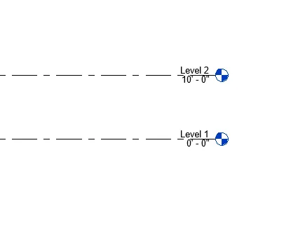
- From the project browser > elevation > east
- Default two level are display as shown
Step2:
- To create a new level go architectural tab select the level
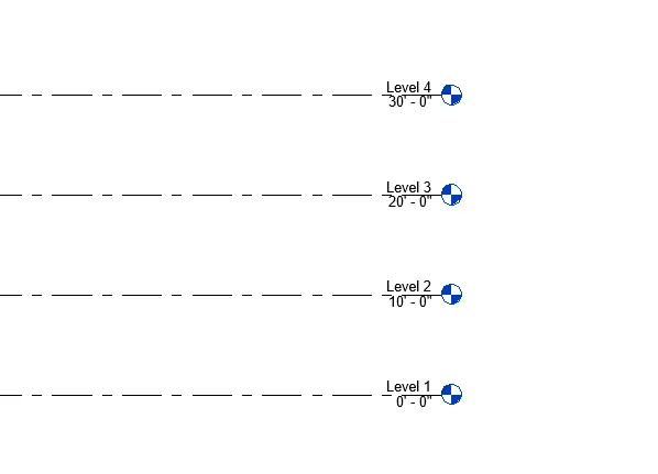
- Keep the cursor at the last end point of the level give the unit as 10’ and draw a line from the left to right is level three
- Similarly create the next level for roof
Step3:
- To change the names of the level
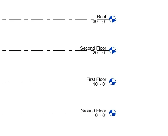
- Just double click on the level 1 and rename as Ground floor
- Similarly rename all levels up to roof as shown
Step4:
- To create Grids as per given data
- Grids Transverse Grids A, B,C,D, E @ 10’ spacing
- Longitudinal Grids from 1 to 10 @ 20’ spacing
Step5:
- From the architectural toolbar select the grid. Grids are create as left to right and top to bottom
- Mark the vertical line for grid and rename it as 1
- From the g
- Last grid keep the cursor and give distance as 20’ and rename the gride as 2
- Similarly create upto 10 no.of gride as given
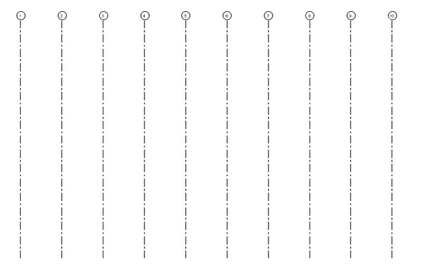
Step6:
- To create horizontal grid form left to right
- Select the grid mark a line and rename the grid line a A
- From the last grid line mark the distance as 10’ and rename as B
- Similarly create grid up to E as given.
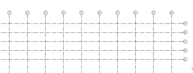
Result:
- Levels:
- Grids:
5):
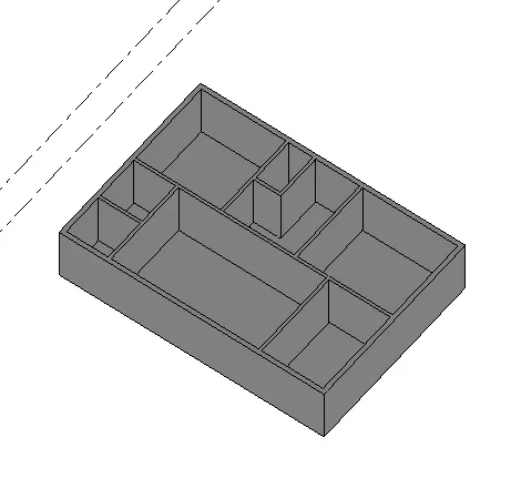
Aim: To create a conceptual layout of the of residential unit 3D modelling.
Introduction: To create a conceptual layout of the of residential unit 3D modelling. By using Revit.
Procedure:
Step1:
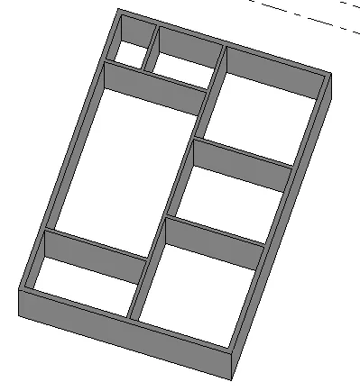
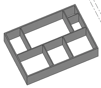
- To create layout of a residential building
- From the architectural toolbar select the wall
- Select a wall and edit wall type as 9” for exterior
- Select the 6” wall for all interior walls
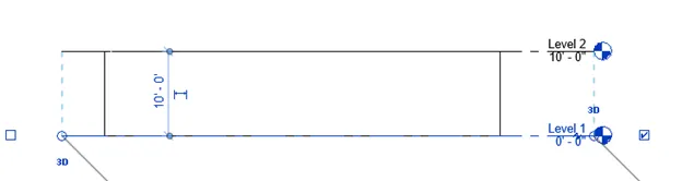
- Give height of wall as 10’
Step2:
- From the property bowser go to elevation part and check the level height as shown
Step3:
- From the toolbar select the view tab to view in 3D. select the 3D view as shown
Result:
6):
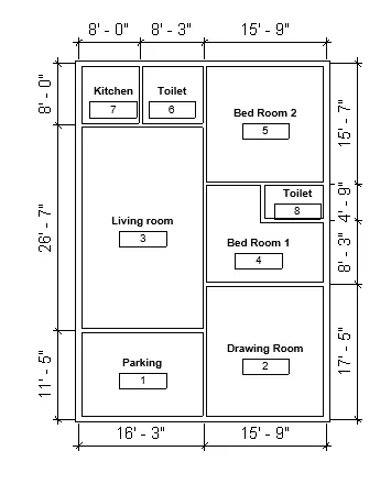
Aim: In the layout created adding. Dimensions of room, components.
Introduction: In the layout created adding. Dimensions of room, components. By using Revit
Procedure:
Step1:
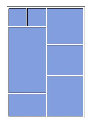
- Adding floor to plan
- From the architectural toolbar select the architectural floor
- From the edit tab set the floor thickness as 6”
- Then click on first point and second point for the floor placement
Step2:
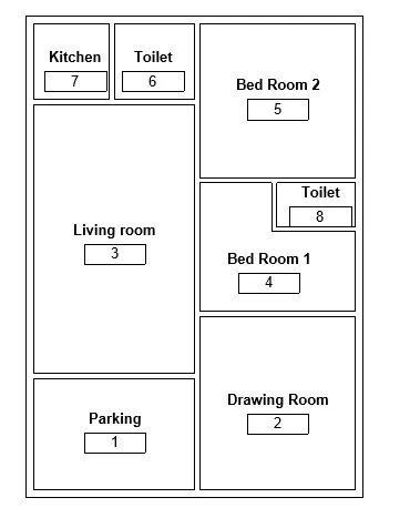
- Adding room tags
- From the architectural toolbar select the room tag
- Now keep the cursor at close boundary and give the room tags
- Then double click to give names of room as per required
Step3:
- Providing dimensions to plan
- From the toolbar select the annotation then click on the aligned dimension
- Now click on the first point and second point to give dimensions
Result:
7):
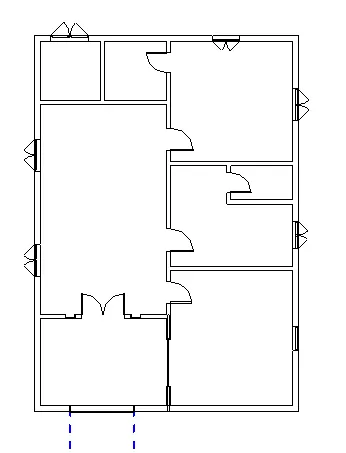
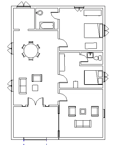
Aim: To identify the residential model elements such as Door, Windows, Tables, Chair, Couch, Bed, Lamps from the library
Introduction: To identify the residential model elements such as Door, Windows, Tables, Chair, Couch, Bed, Lamps from the library. By using Revit
Procedure;
Step1:
- Placing of Door and Windows
- From the toolbar select architectural then click on door and select the as per requirement
- From the toolbar select architectural then click on windows and select the as per requirement
- Select the load family option for the type of door and windows and different sizes
Step2:
- Placing of furniture
- From the toolbar select architectural then click on components and select the as per requirement
- Select the load family option for the type of door and windows and different sizes
Result: