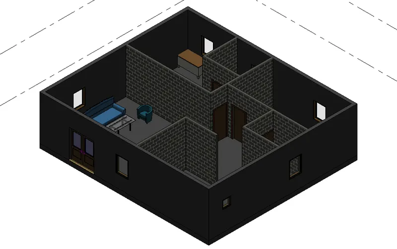
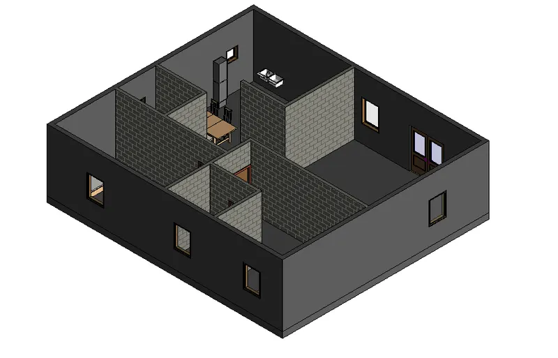
Creating Levels, Grids, Layout and model elements for a residential unit using REVIT
1) What is BIM? Summarize the features of BIM and benefits of using BIM over 2D CAD tools.
- Building Information Modeling (BIM) is the complete process of creating and managing information for a built asset.
- It is a highly systematic process which allows architects, engineers, contractors, manufacturers, and other construction professionals to plan, design, and model and analyze a structure or building.
- It can also give acess to the operation and management of buildings using data that building or structure modeled by other planners such as ,an electrical planner can get acess to structural modeled building to complete electrical work to that building.
Features of BIM:
- BIM models not only present 3D geometric view of the structure, they provide a more detailed overview of the entire building process.
- BIM design tools allow you to obtain various views from a building model and produce high-quality, accurate drawings.
- It covers every component in this process from geometrical aspect of the design to 3D relationships,from topographical information to quantities or properties of building components,etc.,
- BIM is a physical representation of the physical and functional characteristics of the building process, that provides every minute detail of the project.
- One can easily access the right information at the right time that provides a proper infromation for decision making during a structure’s entire shell life.
- BIM are allows to work in three dimensions, time and cost being as additional dimensions.Thus able to produce accurate cost and material estimates.
Benefits of using BIM over 2D CAD tools:
- Time saving-3D BIM offers more time savings over 2D CAD. Change management is largely an automatic task in 3D BIM. Because drawings are linked to the 3D model, all dimensional and geometric changes made in the model are automatically corrected on all relevant drawings.
- Coordination between teams-3D BIM makes coordination among different teams to acess the file. Using the same model and resources architects, engineers, and contractors canwork together to design and construct a project.
- Real time basis- this eliminates the possibility of a drawing or schedule being overlooked and not getting updated with the corrected information which is a real drawback with 2D CAD.
- Error reduction-Using 3D BIM software can reduce potential errors.It's easier to identify interference between elements and spacial problems in 3D than 2D.
2) Understand the concept of Categories, Families, Elements, Instances in Revit. Go to Insert Tab, choose a category. Pick a family and element. Understand the instances and insert it to Revit model.
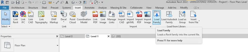
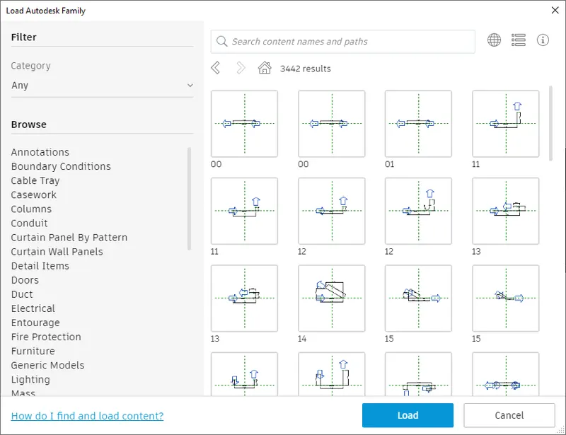
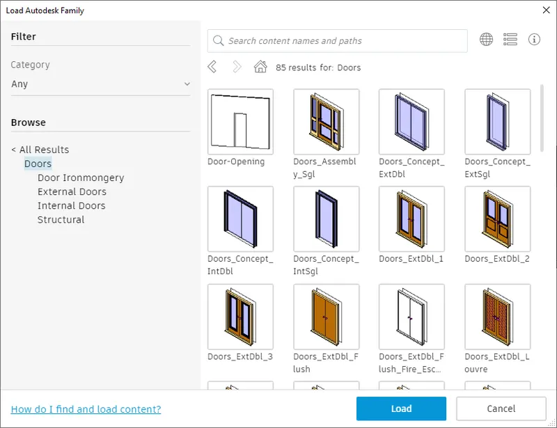
In order to understand the concept of category,family,elements,instances in revit-go to insert toolbar and select load family icon/load autodesk family.
1)Category-
- A Category controls the organization, visibility, graphical representations, and scheduling options of Families within the Project.
- Family are grouped and sorted by category in the library.
- For example- category like door,windows,column comes under family.
2)Family-
- A group of components used to build a model,with a common set of properties and a related graphical representation.
- For example- walls few are present within revit and few are choosed from library,doors-residential door.
3)Elements-
- All elements in the revit platform are part of family and they fit into a clearly defined order.
- Element contains the geometric definition of the element and the parameters used by the element.
- Each instance of an element is defined and controlled by the family.
- Model elements represent the actual 3D geometry of the building.
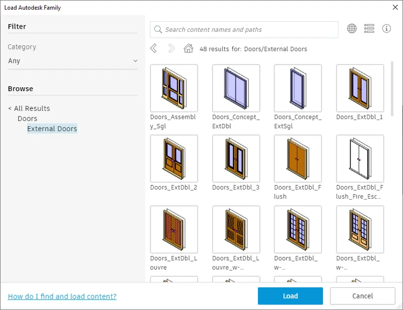
- For example- from family select windows-it display varies dimension of window.
- select the window and apply to the model,its property will be displyed in left side of screen.
4)Instances-
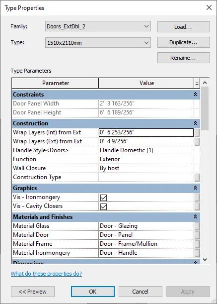
- It is an individual geometric element placed in model,example double door/sliding door etc.,
- It holds instant parameter belongs to individual instances only.
- from below,a double door placed in wall is called instance.
3)Setting up a Project – Open a project file with architectural template. Save the file with appropriate name. Set up the project units to Imperial / Metric based on your convenience of modelling. Complete the project information under Manage tab. Set up the maximum backups for project file to 3.
AIM:
- Set the a architecural project and save with building_1 name.
- Set the units to feets.
- Complete the project information under Manage tab.
- Set up the maximum backups for project file to 3.
INTRODUCTION:
File menu is the panel here a file can created,opened,saved,print or export/import.
It holds of different category of project such as architecural project/project template,strcutural project,construction project,mechanical project,electrical project and plumbing project.
PROCEDURE:
- Open the revit 2022 file from windows start.
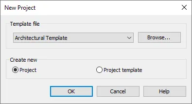
- click on new file and select architecural template.
- open file menu and select save.
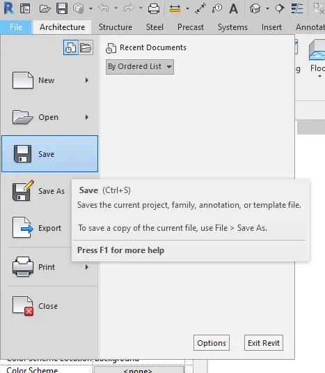
- choose the windows to save file and name has building_1.
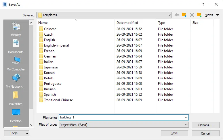
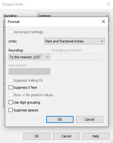
- once the project is saved,go to manage toolbar and select project unit.

- set the units to feet and inches.
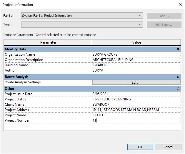
- again select project information from amnage toolbar.
- the information display-fill the up the data and click OK.
- go to file menu-click on save as.
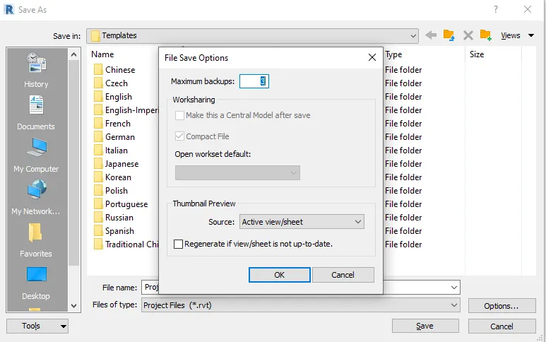
- when display of saved file appears,click on option.
- enetr the maximum backup as 3.
4) Understand the concept of Levels and Grids. Follow the naming and conventions. Create the following Levels: ( Convert to metric equivalents if metric is your units)
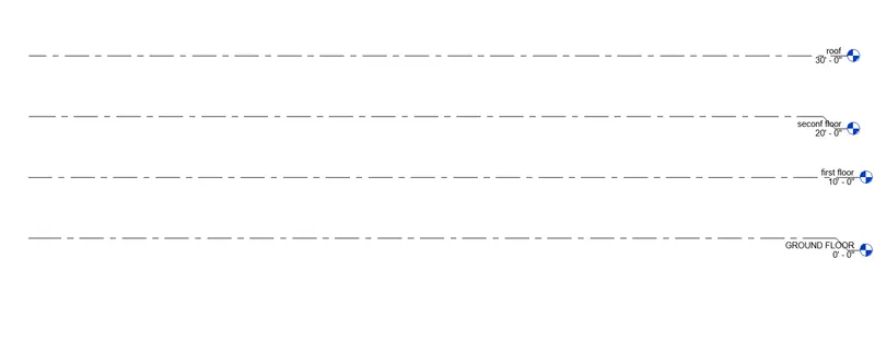
Ground Floor @ 0’
First Floor @ 10’
Second Floor @ 20’
Roof @ 30’
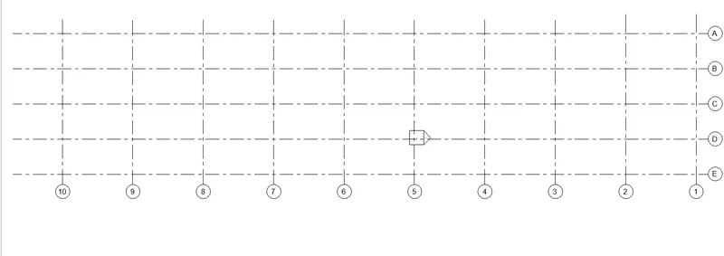
Grids Transverse Grids A, B,C,D, E @ 10’ spacing
Longitudinal Grids from 1 to 10 @ 20’ spacing
AIM: to create grids and level using above given details.
INTRODUCTION:
- Levels and grids are finite planes that help to define project context.
- Levels in Revit are used to indicate the locations of floors, foundations, and the roof of a building in section and elevation views.
- Grid lines are added to a model to create a reference and framework for the design.
- You can drag their extents in elevation views so that they do not intersect level lines. This allows you to determine whether grid lines appear in each new plan view that you create for a project.
- Grids can be straight lines, arcs or multi-segmented.
PROCEDURE:
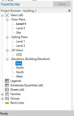
- In order to create levels,select elevation view(east) from projeect browser.
- add the levels at specified distance by selecting level tool from datum panel of architecural toolbar.

- now select grid from datum panel.
- click on the horizontal lines at distance 10' and drag to other end.
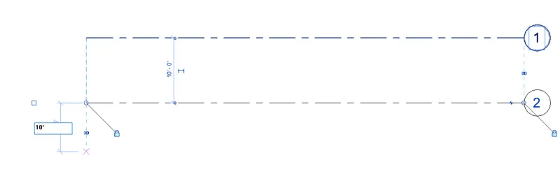
- label them as ABCDE.
- simialrly create 10 vertical grids at distance 10' each.
- label them as 1-10.
RESULT:
5) 3D modelling of residential unit – From looking at your house / or a place you aspire. Create a conceptual layout of the residential unit. You can measure using a tape or
you can access your residential plan to create a similar layout.
AIM: To create a conceptual layout of residential building.
INTRODUCTION:
- The Revit model is a virtual version of the building design.
- 3D modeling refers to the process of creating a mathematical representation of a 3-dimensional object or shape.
- The model describes not only the geometry of the model elements, but also captures the design intent and logical relationships between the elements in the model.
PROCEDURE:
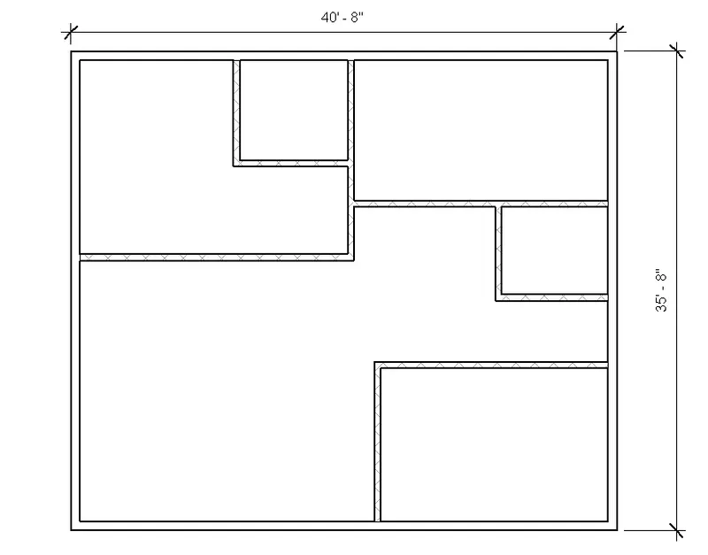
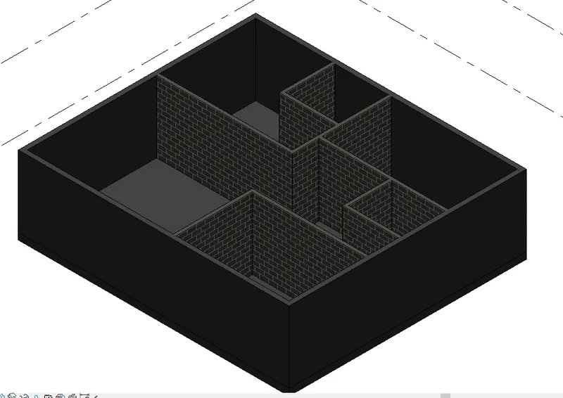
- select architecural wall of element genric wall 8" for extreior and 6" for inetrior.
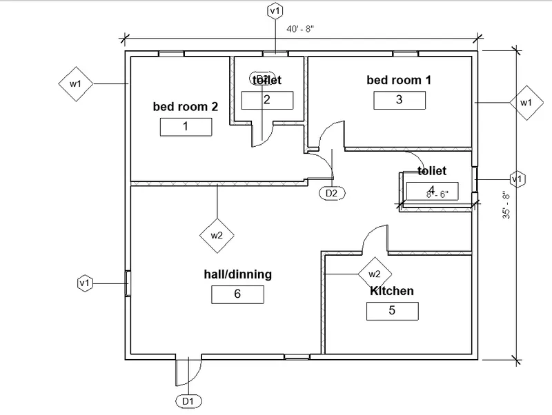
- create a layout of dimension 40'-8"x35'-8".
- subdivide the layout for making of other unit building such has hall,kitchen etc.
- once the wall are drafted,use annotate toolbar -linear dimension to measure the layout.
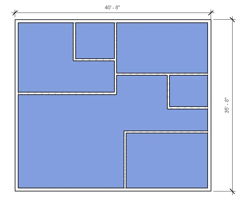
- now create a floor option using floor command in architecural toolbar.
- use rectangular option and create.
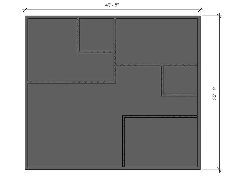
- change the visual style from wireframe to shaded graphics.
- now go to view toolbar and click on 3d view.
RESULT:
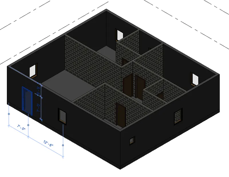
6) In the layout created draft the level of details you are planning to include – Dimensions of room, components you plan to add in the residential unit.
AIM: To add detail to the drafted resdiential unit such as dimension,door and window components etc.
INTRODUCTION:
- Drawing dimensions are added to a drawing to further document the model, without changing or controlling features or part size.
- A dimension in a drawing view is the process of retrieving a dimension that has been applied in the modeling.
- Components are impacts that are individual element from family added to modeling for detail defination.
PROCEDURE:
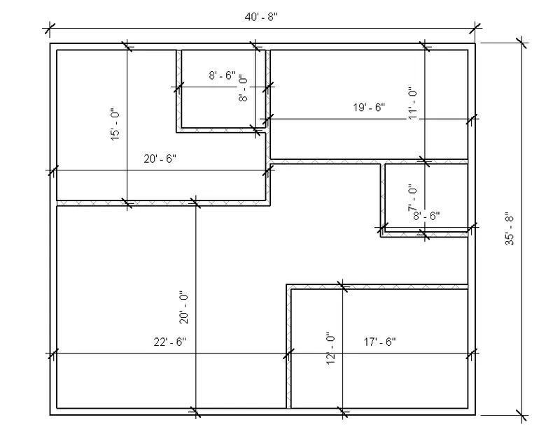
- Once the residential unit is drafted.
- go to annotation toolbar and select alligned dimension tool.
- place the cursor at one end of wall and move to another end and click on the wall.
- dimension is measured from core center of the wall.
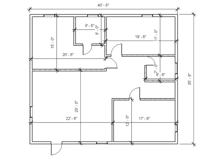
- now click on door component from architecural and select type of door to be placed and click on wall.
- simialry repeat the same for windows also.
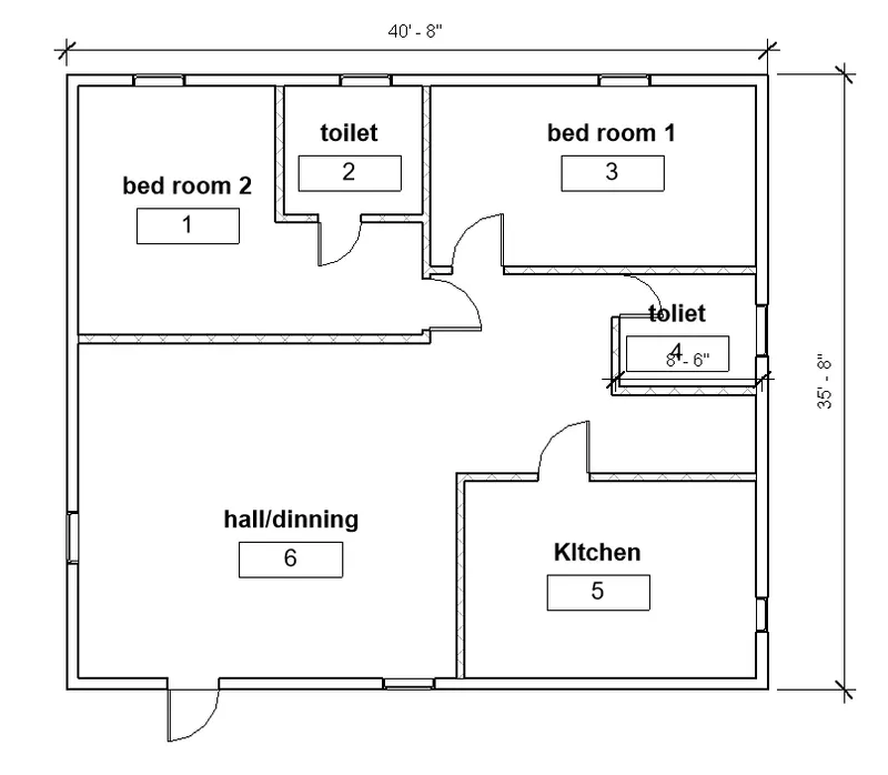
- now use text command from annotate toolbar and click on area -type.
- can also use tag by room command,place cursor on boundry to tag.
- rename them as per required names.
RESULT:
7) Identify the residential model elements such as Door, Windows, Tables, Chair, Couch, Bed, Lamps from the library and insert them to the model .
AIM: To label the model elements such as door,windows,chair,bed etc inserting from library and tag by category tool.
INTRODUCTION:
- now select tag by category from panel and click on wall componets name as W1.
- similalry same for partition wall,doors and windows.
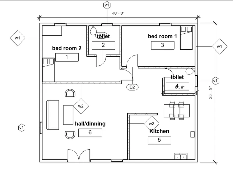
- select the kichen components such as dish washer,fridge etc from library and place it.
- similalry select beds and lamp for bed room.
- couch and table for hall and urinals for toliet.
RESULT: