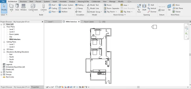
Creating Levels, Grids, Layout and model elements for a residential unit using REVIT
Question 1) What is BIM? Summarize the features of BIM and benefits of using BIM over 2D CAD tools.
Aim : To know about BIM and its features and its benefits over other 2D CAD tools.
Answer : BIM – Building Information Modelling is a process which includes planning, designing, constructing, co-ordinating and 3D modelling of a Project. It is a process in which all the information of the 3d building models are linked in coordination to produce digital 3D model of the project. So Autodesk Revit supports BIM tool by creating data based model of different disciplines such as Architectural, Mechanical, Structural and MEP designs.
The Key features of BIM:
- Coordination - This is the main feature in Autodesk Revit BIM tool through which we have the ability to store and share the relevant data or information to different disciplines of teams such as Mechanical, Architectural and Structural of a project. If any changes made in data input is automatically updated in all the Revit Output designs and drawings.
- Computation – Auto-cad Revit as a BIM tool also helps in computation of Material Schedule, Quantity Schedule and also in Energy Evaluation of Projects.In structural Discipline it helps in Robo Structural Analysis which helps in computation of the response of Loads that are applied on buildings.In mechanical discipline it helps to get computation of Fluid Dynamics Schedule and Thermal Calculations.
Benefits of BIM tool over 2D Cad tools
- BIM as tool helps in coordinating with different disciplines such as Mechanical, Structural and Architectural teams which in turn helps in better coordination and Clash detection in team members also in improvised outputs.
- If any changes made in database it will be automatically updated in connecting drawing such as elevations and D models hence there is no need to redraw the drawings.
- This helps in Cost effective and Time effective models.
- Finally model based Cost estimates, Material schedules and Quantity schedules can be obtained.
- Revit supporting BIM tool has a huge database of Families and Categories which helps in creating real time drawings so that we can visualize projects in Preconstruction stage only.
- All these features overall increase the productivity with prefabrication.
Question 2) Understand the concept of Categories, Families, Elements, Instances in Revit. Go to Insert Tab, choose a category. Pick a family and element. Understand the instances and insert it to Revit model.
Aim: Understanding the concept of Categories, Families, Instances of Revit. Inserting Categories from Family and Elements and also understanding their uses in Revit.
Answer : Revit software is created in the form of hierarchy which lets user to add more details to the project. It is imp to know the Hierarchy of these parameters in Revit in order to understand which element is editable and which category is creatable so that more details can be added to the project to make it more realistic.
Category : In Revit software Categories means the properties that are already present and which are predefined by the software like walls, Doors, Windows or Floors. We can insert new category of our own and define elements of our choice under a particular category. Hence category constitutes a group of elements that share a common property.
Family : Family is a group of elements that share a common property. In other words, Families nothing but collection of like items sharing the same overall characters (looks and behaviour).
For example: If we attach a door to wall. The door and wall are two different categories but in that door category we get different patterns such as Single flush door / double flush door these will constitute a Family. Same as in the walls we get Generic, Concrete Masonry walls which will constitute Wall family.
There are two types of Families depending on their behaviour are present in Revit.
- System Family: System Family includes elements that are already predefined by the Families can’t be modifies by user.
- Component (Loadable Family): This includes the elements which are created by user with their own customization and loading into Revit unlike the System Family. Revit supports users to create, delete and modify component families.
Elements : Elements are the 3D geometrical representation of the parameters within a Family. There are 3 types of elements
- Model Elements: Model Elements represents the 3D geometry of the project.
Ex: Walls, windows, roof, slabs, sinks, ramps etc.,
- Datum Elements: These defines project context such as grids, levels, reference datums etc.,
- View specific elements: As name suggests this parameter can be displayed only in the view which are placed.
Ex: Text notes, Tags, Symbols, Annotation Elements etc.,
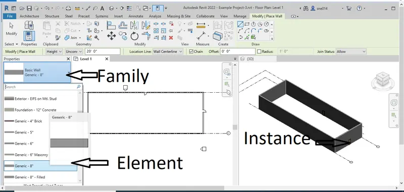
Instances: Instances are the properties of individual elements which are placed in the projects and have specific locations. Each element that user place in project is an instance of a particular family. Elements have two sets of properties
- Type properties: Here all the elements have same type properties and each element has same value for all the instances of a particular family.
- Instance properties: Here the value of these properties may vary according to their location of the element in the project.
For example: The dimensions of the window is type property while its elevation from level is and instance property.
Similarly, the cross-section dimension of beam is type property while its length will be an instance property.
A graphical representaion of Category, Family, Elements and Instances will be as shown below :
Question 3) Setting up a Project – Open a project file with architectural template. Save the file with appropriate name. Set up the project units to Imperial / Metric based on your convenience of modelling. Complete the project information under Manage tab. Set up the maximum backups for project file to 3
Aim: To open a project file in architectural template and saving the file with proper name and then setting the project units to Imperial or Metric based on the convenience and filling up the project information. Setting up back ups for project file.
Procedure: To open e new file,
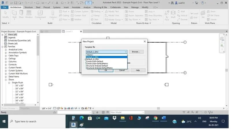
1)Go to File toolbar. Their click ‘new’ tab on it.
2)A small window will open. If u can select which template are you going to work for that u have to select.
Architectural template /Construction/structural/ Mechanical.
Architectural template will available in Imperial units by default or if units can be changed to metric also.
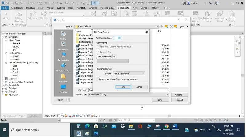
3)Now to save file, go to file toolbar. Then click ‘Save as’ icon.
4)Now go to ‘Project’ icon. Now save file with proper name. For ex: Project_01.
5)In that ‘Save as’ window go to ‘options’ icon.
6)In that set the maximum back-ups to no 3.
7)So that u can have back-up files for your project.
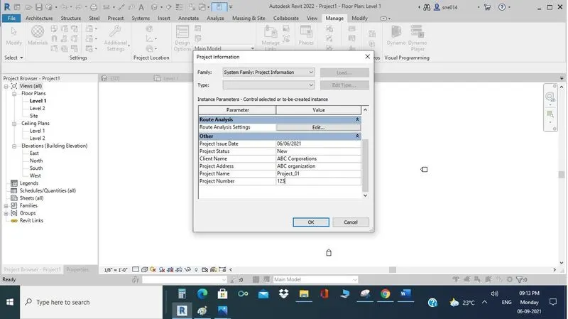
8)Now before starting the modelling of the project, we need to fill the project information. For that go to ‘Manage tab’.
9)Now fill all the Project information as shown in the images below.
Result:
Question 4) Understand the concept of Levels and Grids. Follow the naming and conventions. Create the following Levels: (Convert to metric equivalents if metric is your units)
Ground Floor @ 0’
First Floor @ 10’
Second Floor @ 20’
Roof @ 30’ Grids Transverse Grids A, B, C, D, E @ 10’ spacing
Longitudinal Grids from 1 to 10 @ 20’ spacing.
Answer:
Aim: Learning about Levels and Grids in Revit. Creating Levels at different heights and grids at different spacings.
Procedure:
Levels: Levels are the definite horizontal planes along which the project can be built. Hence these will act as reference for the level-base elements such as roofs, ceilings and floors.With the help of these levels, we can create references for the project like sill level, ground level, roof etc.,We can edit, rename, move and change the heights of these levels.
Creating following levels:
- Go to ‘File’ toolbar. Go to ‘new’ and then click on ‘project’ icon.
- Revit will open with a new project.
- Now go to the ‘elevation’ icon on project browser toolbar and click direction of the elevation say ‘East’
- A new window will open showing the ‘Elevation of the project’. There we can see two levels, one at 0’0” and an0ther at 10’0”.
These show the horizontal planes along which we create our project.
We can edit the names and the heights of the levels.
- In the project browser right click on the ‘Level 1’ icon and rename the level to ‘Ground floor’. Then a small window will appear ‘would you like to rename corresponding levels and views?’ Click ‘ok’.
- Like this create Ground floor at 0’0”, First Floor at 10’0”.
- Then for creating more levels, go to ‘Structure’ tool bar then click on the ‘level’ icon available on the right upper side of structure toolbar.
- Then create two more levels at 20’0” and 30’0” and rename them as Second floor and roof respectively.
Result: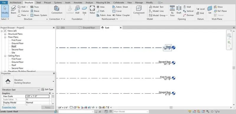
Grids: Grids are the Annotation elements which in organising the deign of project. These are definite planes that can be created at particular spacing to get the reference for the project. These lines can be straight lines and can be arcs or cane be segmented.
Whenever a part or element of the project is changed in the design and it has to be conveyed to the construction field, through these grids only we can convey the place of the element or part.
Creating following levels:
- Go to the ‘Architecture’ tool bar then to the ‘Grids’ icon situated on the right upper side of ‘Architecture’ tool bar.
- Now place the longitudinal grids along the workspace at spacing of 20’0”.
- Place transverse grids across the longitudinal planes at spacing of 10’0” each and rename them as A,B,C,D and E.
Result: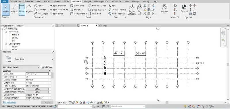
Question 5) 3D modelling of residential unit – From looking at your house / or a place you aspire. Create a conceptual layout of the residential unit. You can measure using a tape or
you can access your residential plan to create a similar layout.
Answer:
Aim: Creating a conceptual layout of a residential unit.
Procedure :
- In the revit software, open ‘file’ in that file menu open a new project.
- Open ‘Architectural Template’ then click ok.
- Then save the project with proper name.
- Then the working space will open in Floor plan ‘Level 1’.
- Then go to the “Architecture’ tool bar. Click on ‘Wall’
- Then select ‘Architectural wall’.
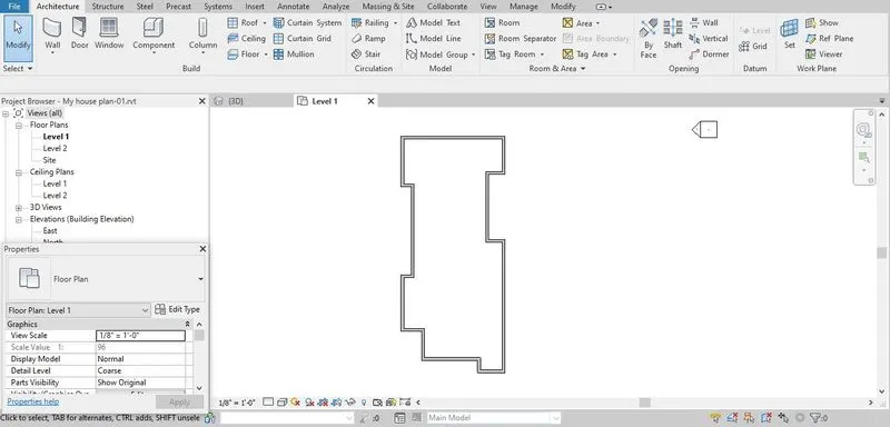
- Then draw the Layout of your residential unit.
Result:
Question 6) In the layout created draft the level of details you are planning to include – Dimensions of room,components you plan to add in the residential unit.
Answer:
Aim: Drafting the details of residential unit and adding components of the residential unit, dimensions, room tags etc.,
Procedure:
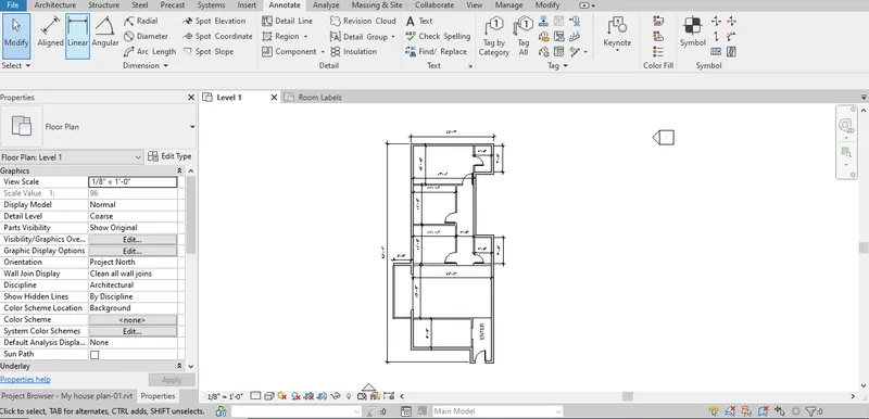
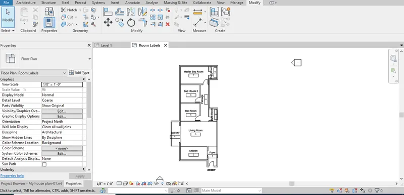
In the layout created, we need to add the details like dimensions, interior walls to create bed rooms, kitchen, bathroom and living room, balcony etc.,
- For adding outer dimension of the layout, go to ‘Annotate’ tool bar them click on ‘Aligned dimension’ and now click on the outer walls. (If the dimension line is aligned for centreline of the wall, change it to the exterior face in the green tollbar shown just above the workspace.)
- Now for adding components of the residential units like bed rooms, bath rooms, living room, kitchen etc., we need to draw interior walls, for that click on the ‘Architecture’ tool bar, then on the ‘wall’ icon then on the ‘wall-Architectural’.
- Now click on the ‘Properties’ tab and select the size of the interior wall such as ‘Interior 5 ½” partition’. Then draw the interior walls in the present Layout.
- Once the interior walls are added we need to add ‘room tags’ (indicates the name of the room and its size and area). For adding room tags go to ‘Architecture’ tool bar then click on ‘room-tags’ icon. (Room-tags will work only when boundaries are closed).
- After assigning the room tags for each room, we can edit the name of the rooms accordingly.
- If we want area and volume of particular rooms, then click on the room tags, then on the ‘properties bar’ click on drop down on’ room-tag’.
- Now click on ‘Room tag with area’ or ‘Room tag with area and volume’ depending on the need.
Result:
Question 7) Identify the residential model elements such as Door, Windows, Tables, Chair, Couch, Bed, Lamps from the library and insert them to the model. Save the project for use for Assignment 3.
Answer:
Aim: Adding doors, windows, furniture and lighting to the residential unit.
Procedure: Once the Layout and Interior rooms are done, now we have to add residential elements such as doors, windows, furniture lighting etc.,
- Firstly, add the doors to the residential Layout. For adding doors, click on the ‘Architecture tab, from that select ‘door’ option.
- From the ‘Properties’ tab, click on the ‘M-Door single Panel’ select the size of the door needed and place it on the exact location. Automatically doors will fit in to the wall.
- Similarly, select the size of each door and place them on the walls wherever its required. We can select any type of the doors, for that go to ‘Insert’ tab and then click on ‘load family’. A new window will open where we have to load different types of doors from the inbuilt library.
(RVT2022-Libraries-English-Us-Doors).
- Likewise, add windows to the walls Here in the ‘window’ we can select the height at which windows can be placed. For that, go to select the window, in the ‘property’ tab, adjust the height of the sill level.
(Different shapes and sizes of windows are available in Revit Library).
- Like this we can add variety of components to our residential units. Before adding the components, we can create a different 'view'. To create a different 'view' right click on the 'Level 1' inside the floor levels of the project browser.
- Then go for ‘duplicate view’ and rename it and save it for the further drafting.
Result: