3D Creation of Celing, Roof, Architectural plan, Structural plan, Sectional view, Elevation view and Camera specific view for a house plan using REVIT
Question 1) Based on the project saved from Week 3, proceed from the First Floor Level. Model a Ceiling from the architecture tab above the walls at the first-floor level.
Aim: Modelling a Ceiling for the project created in Week 3 using Architecture tab for the First Floor Level.
Introduction:
- The process for creating the ceiling is same as of creating floors and roofs only we need to sketch the boundaries.
- Another method is to sketch the boundaries by entering ‘sketch mode’.
- Before we create the ‘ceiling’. We have to select the correct the ‘ceiling plan’ in the project browser.
Procedure:
- Open the Revit project created in week 3.
- In the ‘Project browser’ click on the floor where ceiling has to be created. In this project ‘first floor’ is selected.
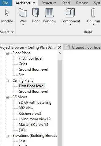
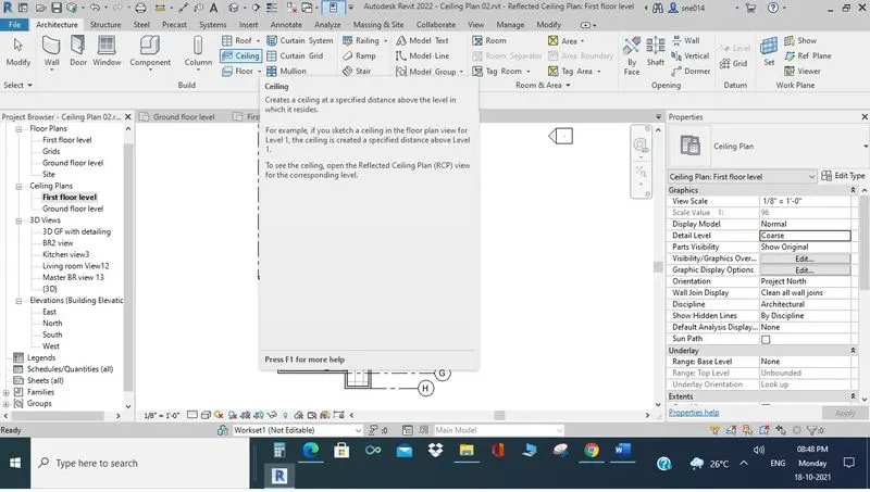
- Go to the ‘Architecture tab’ click on ‘ceiling’. Now click on each rooms to create ceiling.
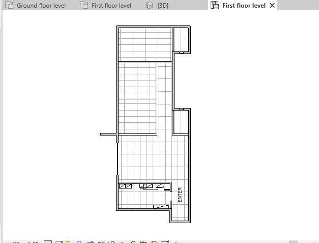
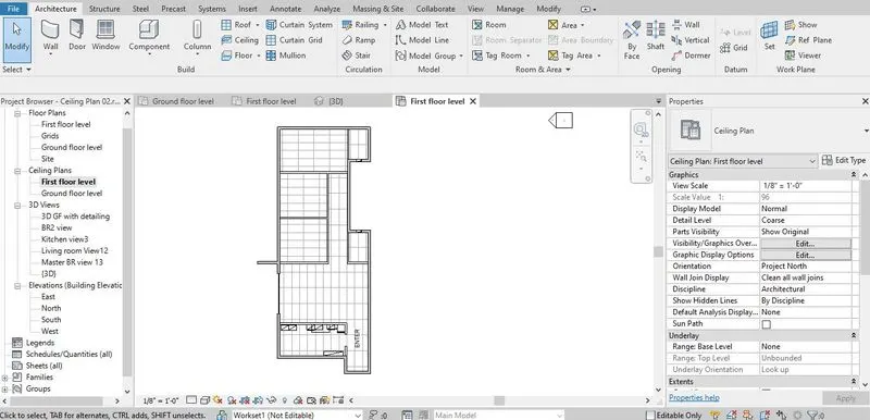
- Ceiling created will be as shown in the fig below.
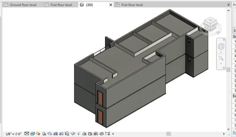
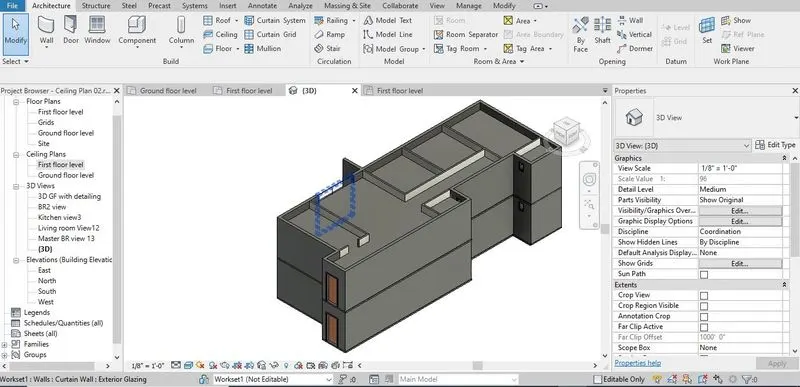
- In the 3D view the ceiling created will be seen like the below image.
Result:
The ceiling for the project has been modelled successfully using 'Architecture tab'.
Question 2) Model a roof above the ceiling by selecting the footprints of the ceiling. Using the adjustment toolbars appearing on-screen adjust the roof slope to 10 degrees.
Aim: Modelling a roof for the ‘ceiling’ created in current Project by selecting footprints of the ceiling and adjusting the roof to 10 degrees.
Introduction:
- Roofs are very important for any building as they give protection from sunlight, rain, snow, winds and from any extreme climate.
- Here in Revit, the procedure for Creating roofs is same as creating floors as here also boundaries need to be defined.
Procedure:
- Before creating ‘roofs’ go to ‘project browser’ and click on desired floor where roof has to be created. Here first floor level is selected.
- Go to ‘Architecture tab’ then click on ‘roof’ then on ‘roof by footprint’.
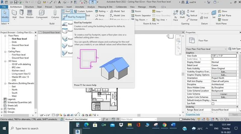
- Now click on ‘boundary line’ to create boundaries. Click on ’finish edit mode.’ Then once the ‘roof’ is created 3D view. Select the ‘roof’
- Now in the ‘properties’ tab and then set the ‘base offset from level to 10’0”.
- Finally set the slope to 10”/12” in the same ‘properties tab.’
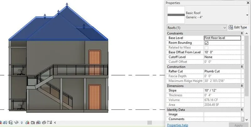
Result: Finally roof created is shown in the below images
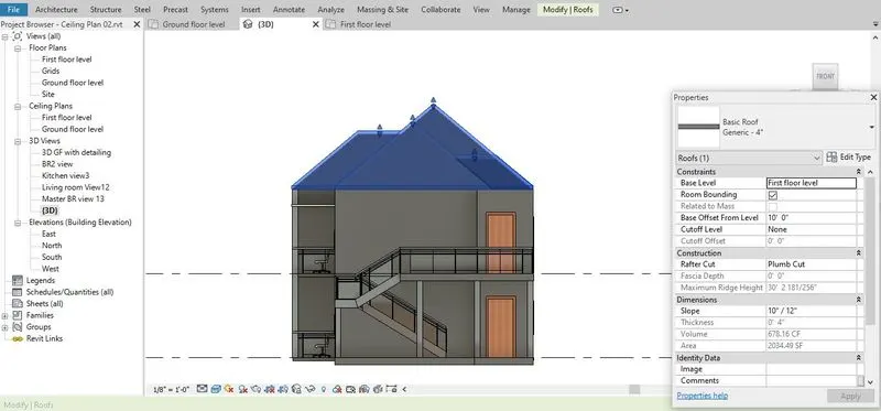
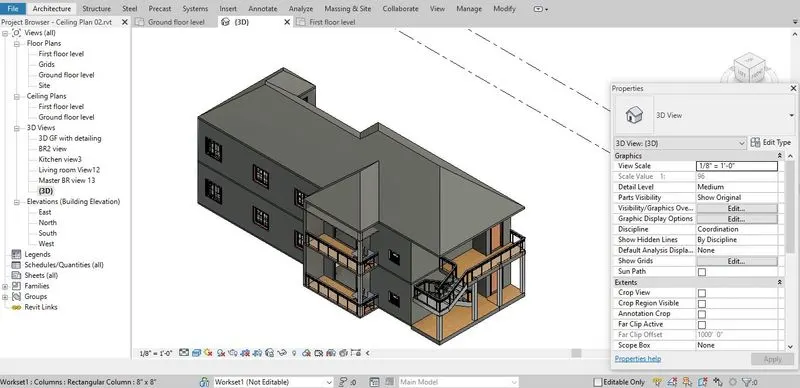
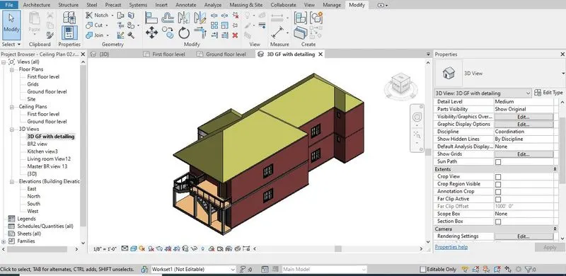
Question 3) Using the file saved from weeks 2 to 4, create plan views for ground floor level and first-floor level including all the walls, floors, and components. Separate them to architecture and structural plans.
- Architecture plan must have walls, floors, and all the components placed within the building.
- Structure plan must have details of only walls, floors, and columns.
Aim: To create separate architectural and structural plans for plan views for ground floor and first floor for the model created in week 2.
Introduction:
Plan views are basic views in any of the project.
All the projects have at least one or more floor plans depending on the levels of the building.
Architectural plan is the engineering drafting of the project which includes walls, floors and other engineering components.
Where as, Structural Plan includes structural detailing of the project such as beams columns etc.,
Procedure:
To draw a model in Architectural plan, open the drawing in the ‘Architectural Template’ then begin to draw the model.
- Now add the ‘Architectural details like walls, floors, doors and windows one after the another we get required view.
- Now go to the project browser go to the ground floor plan then right click on it. Then go to the duplicate view and rename it as ‘ground floor structural plan’
- In this structural plan only show columns, floors and walls created.
- In the same way create ‘first floor structural plan’
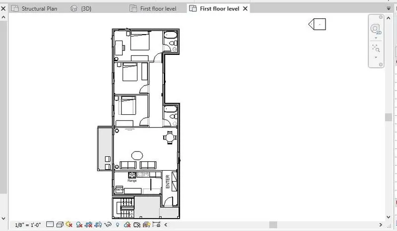
Result: Architectural Plan of Ground floor and First Floor.
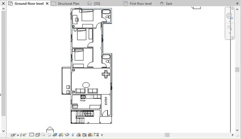
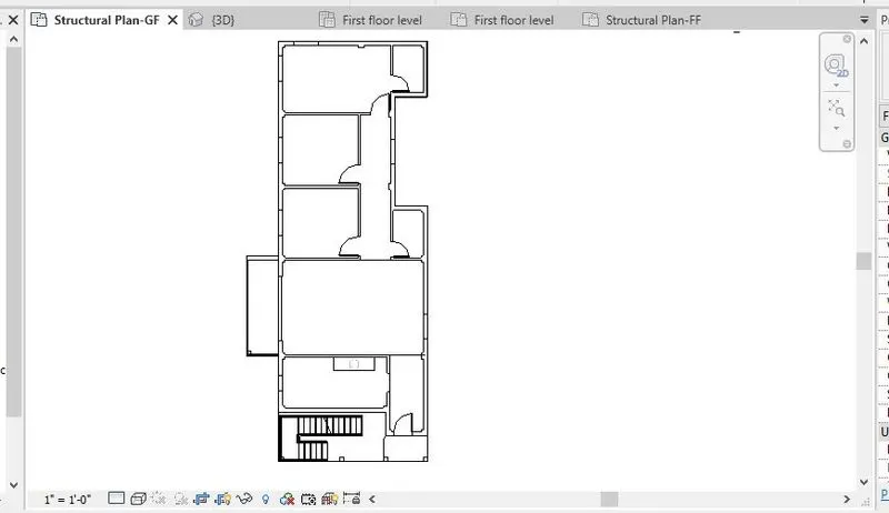
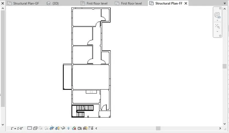
Strutural plan of ground floor and first floor are attached below:
Question 4) Using annotate toolbar add dimensions to all the walls and floors with reference to the longitudinal and transverse grids created in the project file
- The architecture plan dimensions include details on where the components are placed within the buildings with relation to grids. Overall dimensions are sufficient for architecture plans
- The Structure plan dimensions must include details on the position of all the walls and interior walls with reference to grids. Locate all the framing components of the building with reference to a fixed point using Structural plans
Answer:
Aim: To add dimensions to the walls and floors with reference to the longitudinal and transverse grids created.
Introduction:
- The structural plan view is the basic default view when the project is started in a structural template. All the projects include at least one or more structural plan according to the levels of the project.
- In the architectural project floor plan is the default view. Every project include at least one floor plan. Floor plan views are created automatically as you add new levels to your project.
Procedure:
- For adding dimensions go to the ‘Annotate toolbar. Click on ‘Aligned dimension’ click on the walls which has to be measured.
- Click on the outer walls to add the dimensions.
- Now click on project browser right click on the ground floor plan. Now duplicate the view and rename it as first floor and now add dimensions to first floor also.
- Similarly in the same way, in the structural plan add dimensions to inner walls and outer walls with reference to the grids.
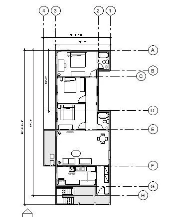
Result: Architectural plan of Ground floor and first floor are added with dimension.
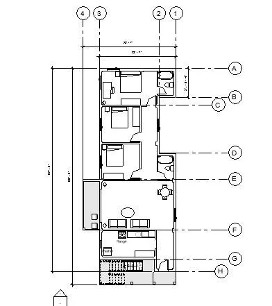
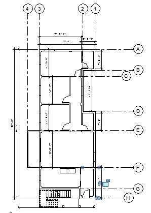
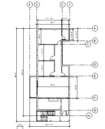
Structural Plan of Ground floor and First floor are added with dimesions with reference with grid lines.
Question 5) Create a sheet template from the view tab and adjust the parameters on the sheet to add appropriate views.
Aim: Creating sheet template from the view tab and adjust the parameters on the sheet to make proper views.
Introduction:
- Creating sheet template is very important in proper documentation of the project.
- When creating sheet template, add sheets in the templates to give clients standard views and levels of the project.
- Before creating views give proper names to those views. Giving proper title block to the sheets will make it standard and professional. Add views to the sheets, using the desired viewport templates and view title types.
- When the project is created using this project template, all of the views and sheets are already created and can be seen in the Project Browser.
- Once the project views are created, start modelling then all the views will be automatically updated in the project views.
- This process will streamline the documentation process and make the drawings very professional.
Procedure:
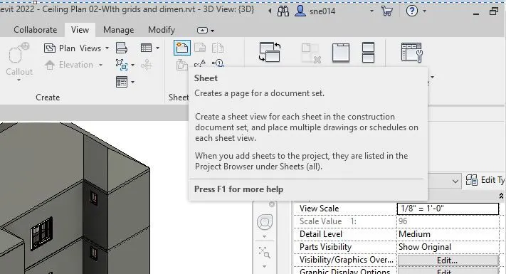
- Click on the sheet icon in the view tool bar.
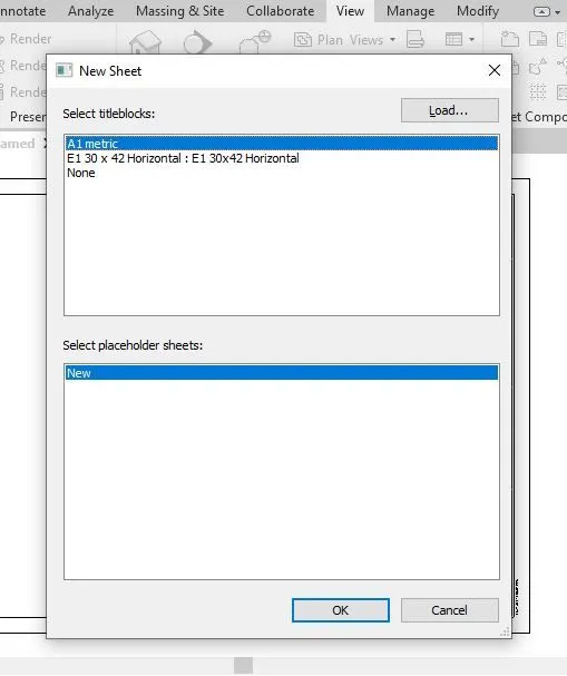
- A new window will open there click on ‘Load’. In that ‘Load family go to English US. Then click on ‘Title blocks’ there all the sheets will be available.
- Select sheet needed from that like A1.
- Once the sheet is open in new window insert the desired views.
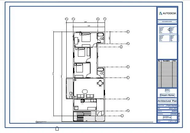
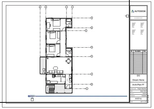
- For placing the views, go to the View toolbar and click on Place view icon and place the desired views like Architectural Plan of Ground floor and First floor into the sheet.
- Edit the title blocks as shown below.
- In the ‘Properties tab’ adjust the scale to get proper view of the project.
Result:
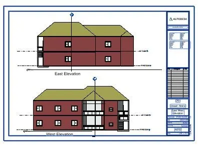
Question 6) Using the elevation tab create the elevation views, looking at your building from East, North, South, and West.
Aim: To create elevation views from East, North, South and West.
Introduction:
- Elevation view is view of the model designed from one particular direction.
- Elevation views gives us the exact picture of the building how it appears from outside.
- Each Elevation chosen refers the compass direction it faces. If we look from the north-view it shows us the southern elevation of the project.
Procedure:
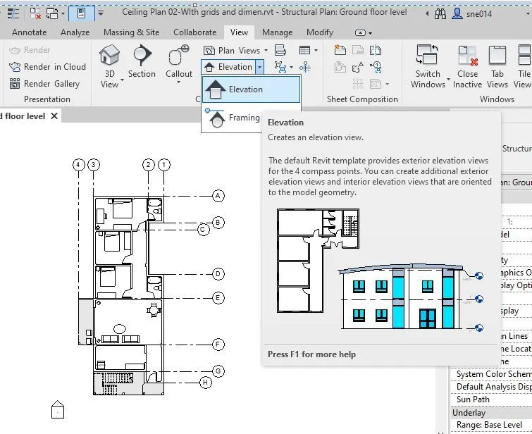
- To get the elevation view, go to the ‘view’ toolbar then click on ‘elevation’ icon.
- Now Elevation from East direction will be visible in a new window.
- Like was All the Elevation views will be appear South, north and West.
Result:
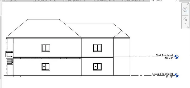
Elevation from East side will be as shown below:
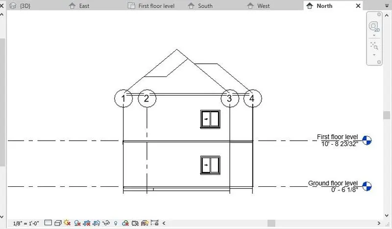
Elevation from North Direction will be as shown below:
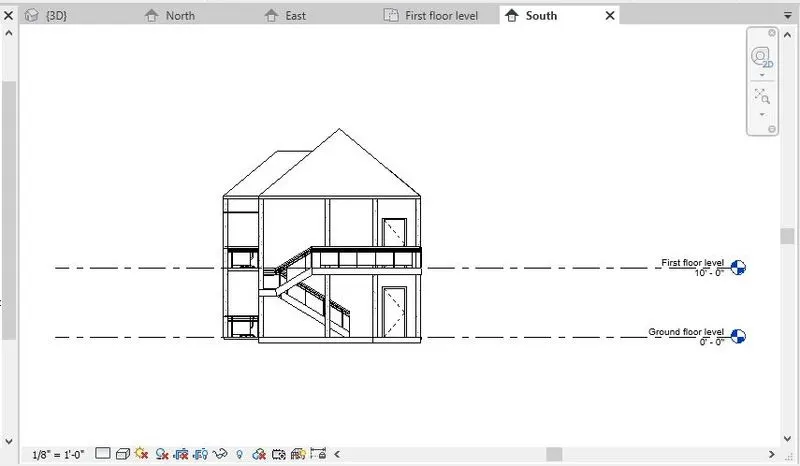
Elevation from South Direction will be as shown below:
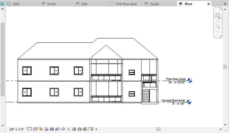
Elevation from West Direction will be as shown below:
Question 7) Produce section cut through each room either cutting across longitudinally or in a transverse direction.
Answer:
Aim: To create section cut through each room longitudinally and Transverse direction.
Introduction:
- Sectional views give us the internal view of the each room in any direction we cut.
- These views will be help us in communicating with clients with more information and detailed views of the building proposed.
- These section drawings will be useful both in Engineering and Architectural fields.
Procedure:
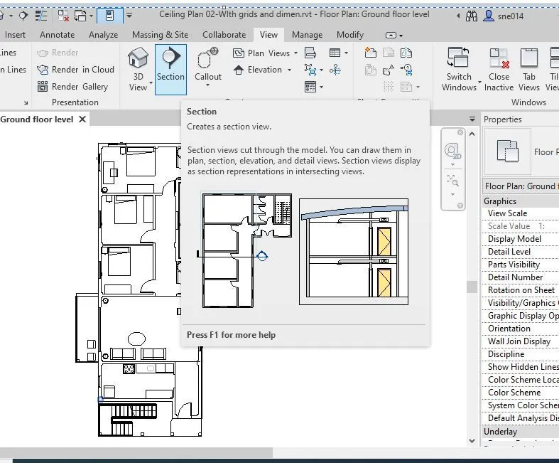
- To get the sectional views, go to the ‘View’ toolbar then press ‘section’ icon.
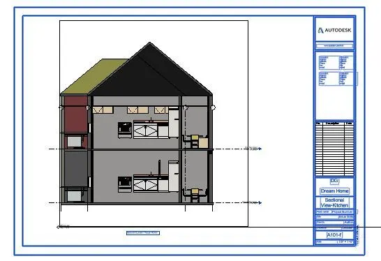
- Now place the curser on the kitchen to get the sectional elevation of ‘Kitchen’.
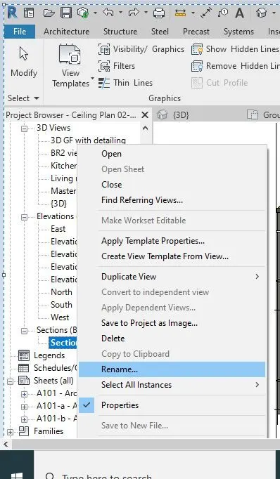
- Now in the Project browser, go to the ‘Sections’ then rename that ‘Section 1’ as Section through Kitchen.
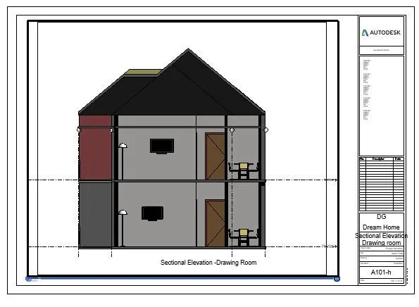
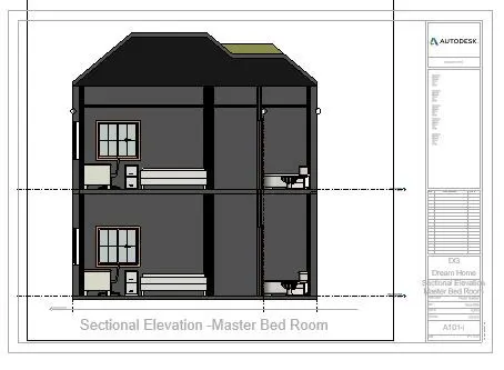
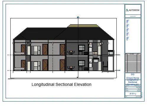
- Now in the same way get all the sectional views of Bed room, Drawing rooms and also Longitudinal views.
Result:
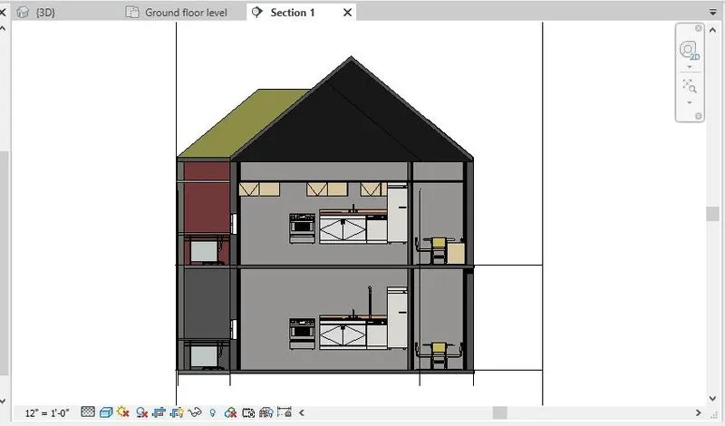
Section cut through Kitchen is as shown below:
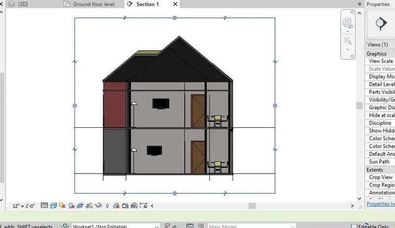
Section cut through Drawing room is as shown below:
Section cut through Master Bed room is as shown below:
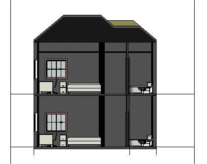
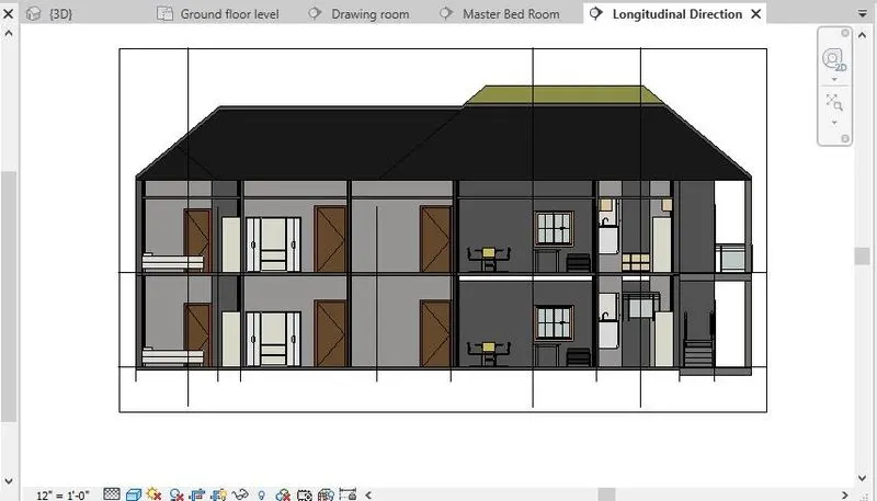
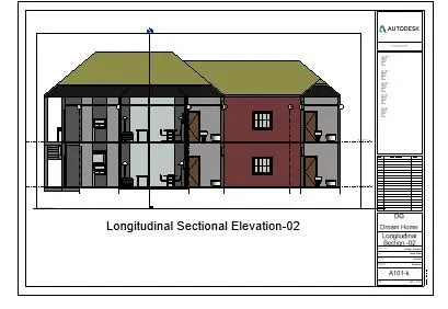
Section cut through Longitudinal Direction along Drawing Room and all the Bed rooms is as shown below:
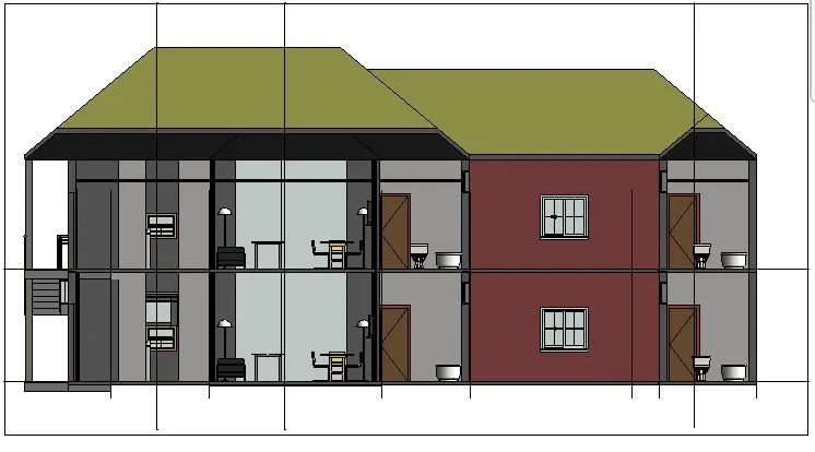
Section cut through Longitudinal Direction along Drawing Room and Bath rooms is as shown below:
Question 8) Classify the views, Plan Views, Section Views, and Elevation views to either Design or Documentation category using Properties browser.
Answer:
Aim: To create Plan views, Elevation views and sectional views for design or documentation.
Introduction:
- Plan view is the basic view of the project in any Architectural project. Most project includes at-least one Floor plan.
- Floor plans can be created automatically by adding the levels to the project.
- Elevation view gives is the appearance of the building from outside.
- This is the most common and most important view of the building as aesthetic point of view.
- Each elevation marks in relation to the compass direction it faces like if we see towards north direction then southern elevation of the building will visible.
- Sections views will give the hidden details inside of the building. We can get the sectional view along Longitudinal and Transverse direction also.
- The sectional views help us in communicating with the clients with more detailed drawings.
Procedure:
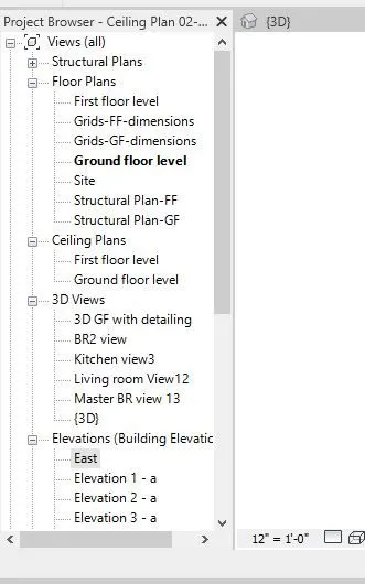
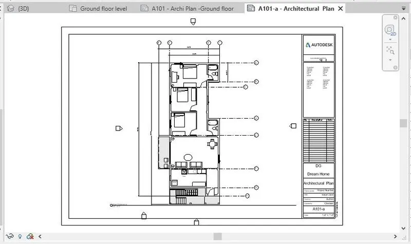
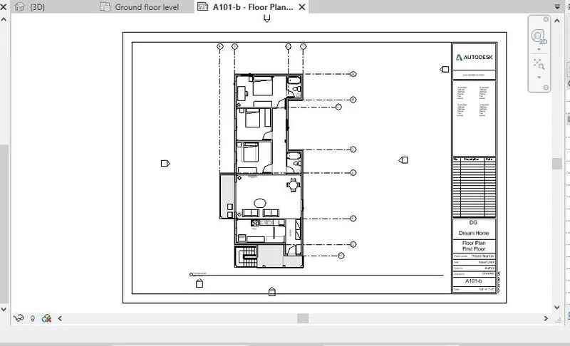
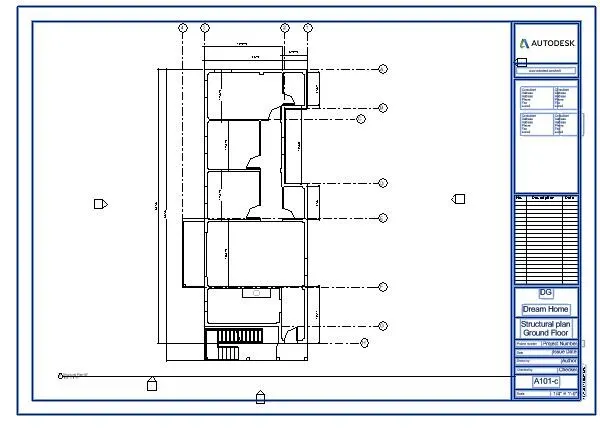
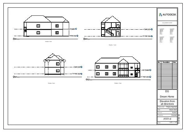
- When we open the project browser, plan views, sectional views and Elevations are visible as shown in figure below:
- Now we have to click on the sheets to insert these plans, sectional views one by one separately.
- After inserting the sheets go to the ‘View’ toolbar. Click on ‘Place view’ and create as many sheets as required.
Result:
Question 9) Using the sheet template produced create multiple sheets as follows
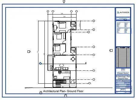
a. A 101- Ground Floor Architecture Plan
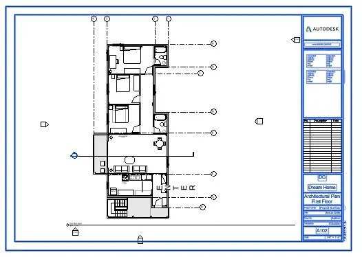
b. A 102- First Floor Architecture Plan
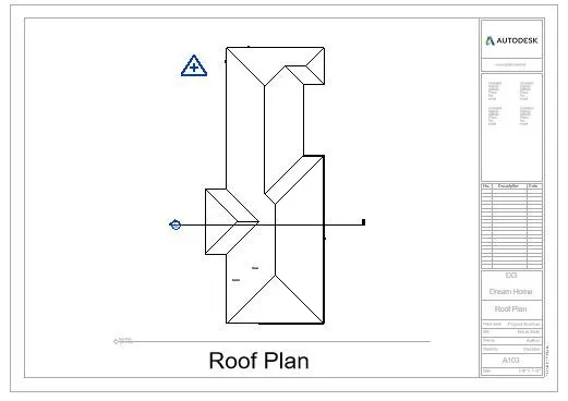
c. A 103- Roof Plan
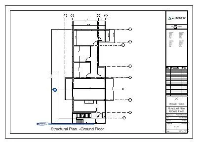
d. S 101- Ground Floor Structural Plan
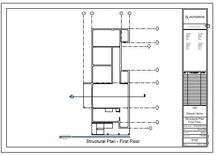
e. S 102- First Floor Structural Plan
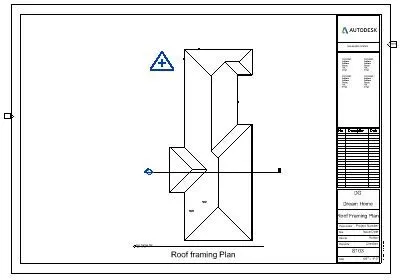
f. S 103- Roof Framing Plan
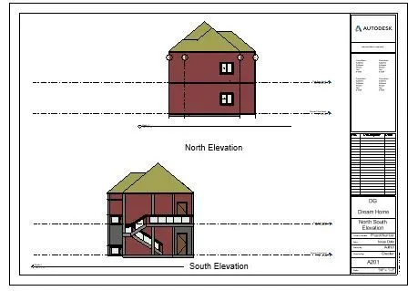
g. A-201- North-South Elevations
h. A-202- East-West Elevations
Add additional sheets based on the sections created in your Revit file
Answer:
Aim: To create sheet templates to produce multiple sheets for plan views and Elevation views.
Introduction:
- Creating sheet template is very important in proper documentation of the project.
- When creating sheet template, add sheets in the templates to give clients standard views and levels of the project.
- Before creating views give proper names to those views. Giving proper title block to the sheets will make it standard and professional. Add views to the sheets, using the desired viewport templates and view title types.
- When the project is created using this project template, all of the views and sheets are already created and can be seen in the Project Browser.
- Once the project views are created, start modelling then all the views will be automatically updated in the project views.
- This process will streamline the documentation process and make the drawings very professional.
Procedure:
- To insert sheet templates, go to ‘view’ toolbar. Then click on ‘new sheet’.
- Then Load the desired sheets from the Library.
- Then Click on ‘Place view’ and insert required views and rename the drawing name and number.
Result:
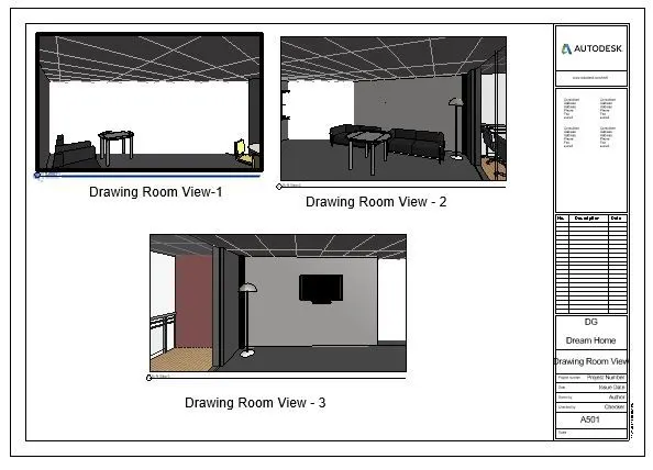
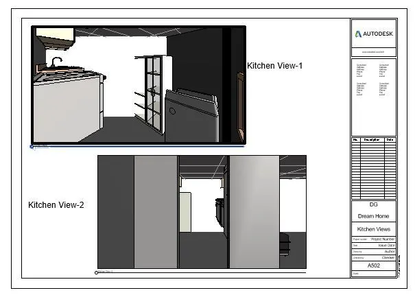
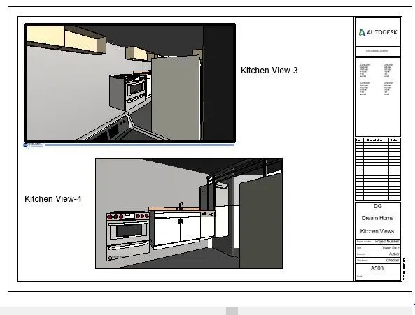
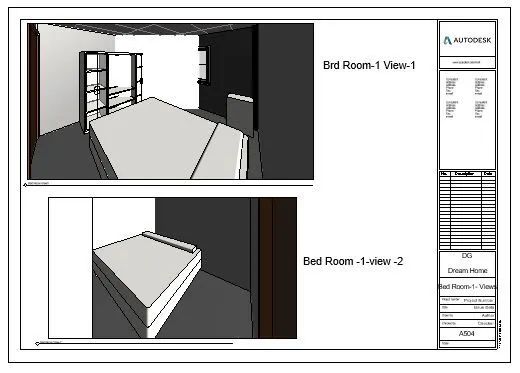
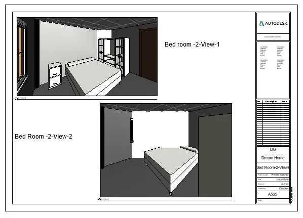
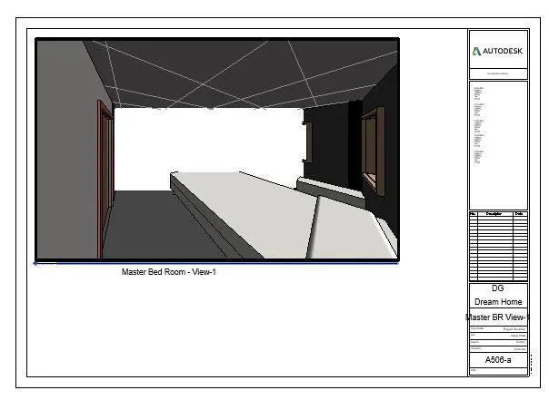
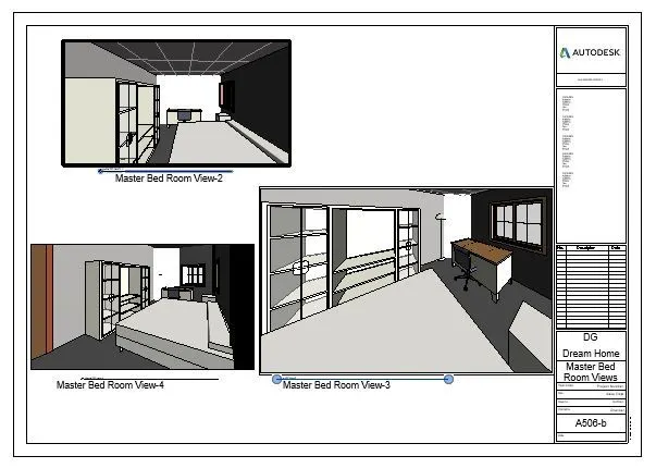
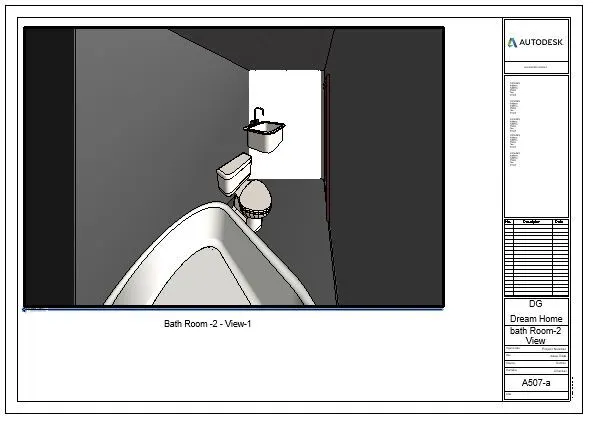
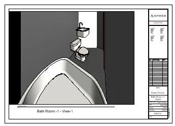
Question 10) Create a camera-specific view or a 3D view in each room ( living, dining, bedroom). Based on the views create a new set of sheets starting A-501 (you can add as many sheets after, 502, 503.. n)to place the 3D view images. Produce the sheets as a part of project drafting.
Answer:
Aim: To create camera specific views or 3D views in each room of the building and putting them in the sheets as a part of project drafting.
Introduction:
- Camera views are the specific views which gives information about the inside of the building.
- These are very important when we are communicating with the clients.
- These views give us ideas for proper utilization of the space inside the building.
Procedure:
- To get the specific camera views, go to the ‘View’ toolbar then click on ‘3 D views’ and then click on ‘Camera view’
- Now click the camera on the room to be pictured.
- Now on the project browser rename the views accordingly.
- Now click again on ‘view’ toolbar and click on add sheets and insert views on the sheets and rename them accordingly.
Result:
**End of Document**