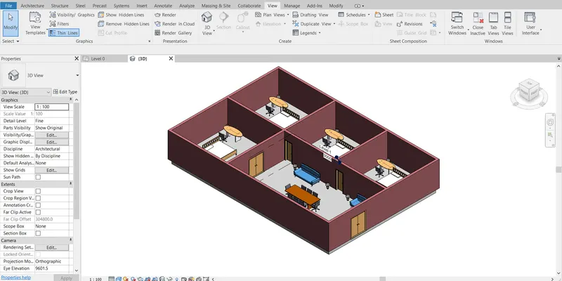
Creating Levels, Grids, Layout and model elements for a residential unit using REVIT
1.What is BIM? Summarize the features of BIM and benefits of using BIM over 2D CAD tools.
- BIM: -
- BIM is a Building Information Modelling
- It’s a Concept Created by Auto Desk
- Revit Helps in Achieving BIM as a Process
Features In BIM: -
BIM is Divided in to 2 types
- Co Ordination 2. Computations
- Co Ordinations: -
- Co Ordination is the Key Feature in BIM
- Revit helps in Co Ordinations of Multiple Disciplines
- Example: - Revit Offers In Coordination’s of projects in Architecture, Structural, mechanical Etc., In Single Projects as Independent Design theme Units
- Computations: -
- Calculation of Quantities of Material, Performing energy analysis in Revit
- To Create Material schedules, Quantity Schedule, Performing Energy analysis In Revit
- In Structural Discipline in Revit, Robo Structural Analysis that Helps in Computing the Response to the Load Applied in a Building
- Auto Desk CFD, For Computing Floor and Thermal Computations in Specification to Mechanical Engineering
- Revit is a BIM tool that Helps in Achieving Coordinating and Computations as Apart of Model
Benefits of BIM: -
- Saving Time
- The Modification of the Model in one View Will in turn Reflect on all other View
- Unlike 2d Cad Tool, we Don’t have to Edit the Modification in the plan elevation Etc., Here in Revit Changes Made in One View Will be Automatically Loaded In all other Views
- The Changes Will Affect the Quantities
- It Will also Reflect in the Paper Space and Model Space
2.Understand the concept of Categories, Families, Elements, Instances in Revit. Go to Insert Tab, choose a category. Pick a family and element. Understand the instances and insert it to Revit model
- Categories: -
- Categories are Group of Elements having Common Properties
- Its Predefined by the Software
- Example: - Wall, Doors, windows
- We Can Insert Element of Our Choice and Create a Category
- It Controls the Organisation, Visibility, Graphical Representation and Scheduling Options of the Family within the Project
- Families: -
- Family is Different Element Having Same Properties
- Eg : - Single Flush Door It has Different Sizes Having the Same Property
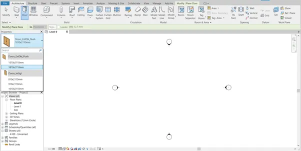
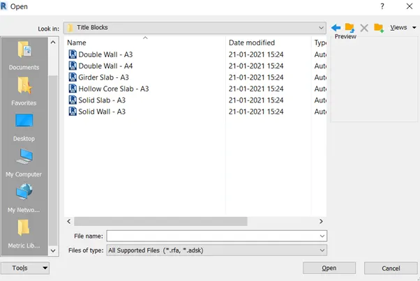
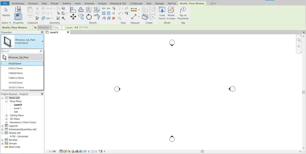
- Families is Grouping of 2D or 3D information that Serves to represent a Discrete Building or Documentation Element in the Project
- It Defines Parametric, Graphical and documentation Requirements
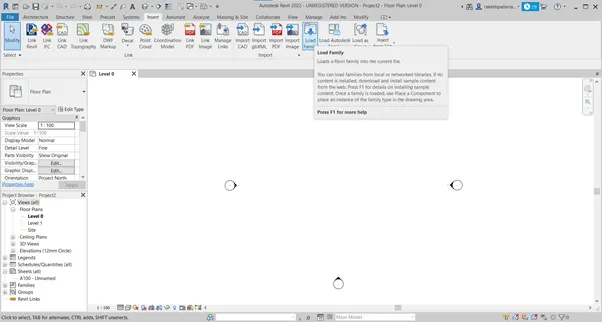
- Go to Insert Tab Click on Load Family
- Elements: -
- Elements is the Basic Features Which Cannot be Subdivided
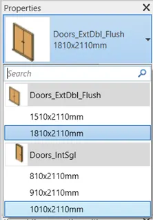
- In Single Flush door, the different Sizes Represent the Element
- Single Flush Door of Size
- Element is a Specific representation in a family Defined by Distinct Parametric Graphical and Documentations Characteristics which Make it Unique from other types in the Family
- Instance: -
- Its an Individual representation of a type in the Project Defined By Unique Parametric Graphical and Documentations Characteristics which make it Unique from other Instances in the Project
3.Setting up a Project – Open a project file with architectural template. Save the file with appropriate name. Set up the project units to Imperial / Metric based on your convenience of modelling. Complete the project information under Manage tab. Set up the maximum backups for project file to 3
Aim: -
- Setting Up a Project by Using Revit Software
- Create a Architectural template
- Saving the File
- Setup Project
- Complete Project Information Under manage tab
- Set up Backups
Procedure: -
- Open the Revit Software
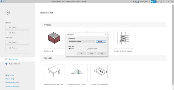
- Click on the New File Select the template File as Architectural template
- Go to File tab and Select the Save Option and Save the name as Challenge-2
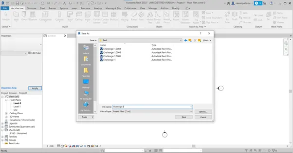
- Click on save
- Go to Manage tab and Click on Project Information Tab
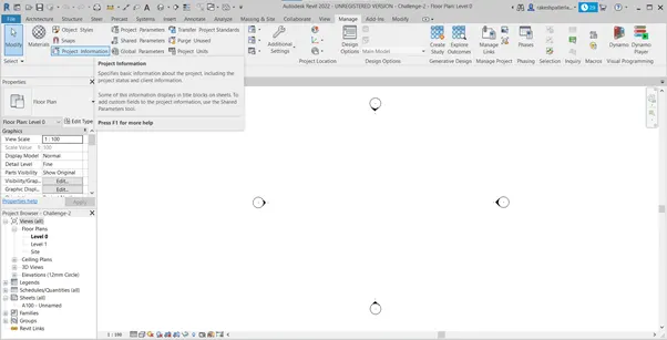
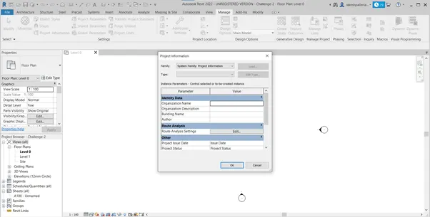
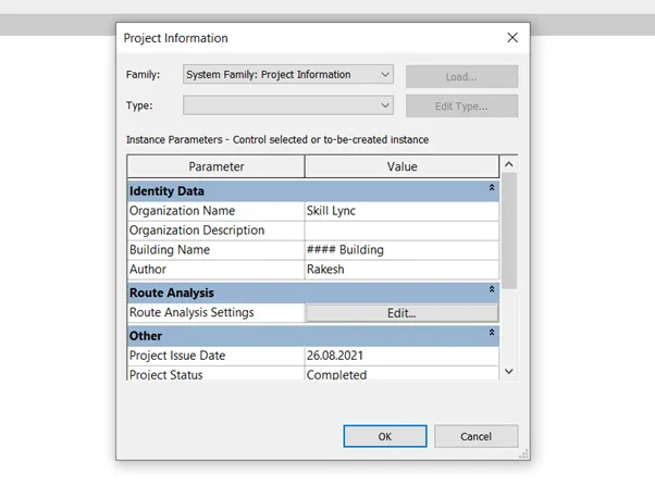
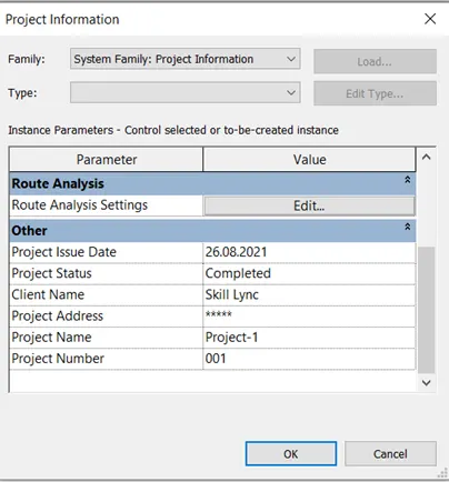
- The Project Information Dialogue Box Appears Enter the Organisation Name Project Detaisl Etc.,
- Setting Backups
- Go to File Menu, Click on Save as Click on Project
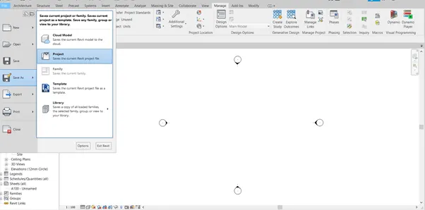
- Click on Options in the save dialogue Box
- File Save Option dialogue Appears, enter the No.of Backups as 3
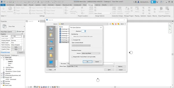
- Click on Ok and then Click Save
Result: -
- Create a Architectural template
- Saving the File
- Setup Project
- Complete Project Information Under manage tab
- Set up Backups
4.
Aim: -
- To Create Levels and Grids
- Ground Floor@0’
- First Floor @ 10’
- Second Floor @ 20’
- Roof @ 30’
- Grids: -
- Transverse Grids A, B, C, D, E @ 10’ Spacing
- Longitudinal grids From 1m to 10 @ 20’ Spacing
Procedures: -
- Open the New Project with Architectural Template
- Go to Elevation From the Left Portion Select East in that Project Browser
- Already there Two levels by Default
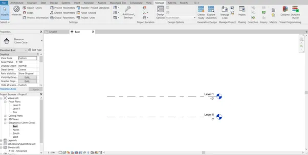
- Level 0 at 0’ and Level 1 at 10’
- Rename the Level as Ground Floor By Double Clicking the Level
- Rename the Level 1 as First Floor
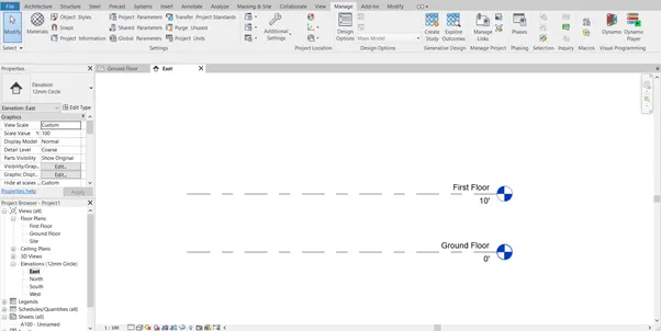
- To Create New Level, In Architectural Tab Click on Levels , Click on Pick Line Option and Give the Offset as 10’ and then Click on the First Floor Level
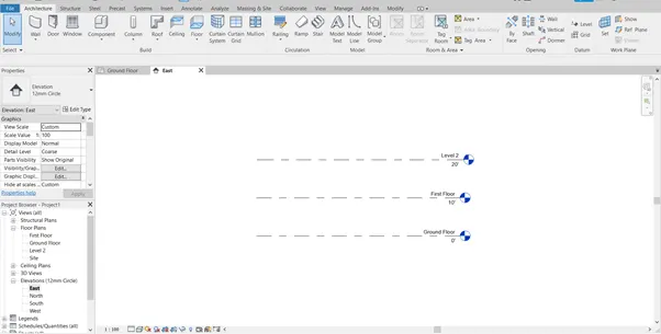
- Level 2 is Created at 20’ from the Ground Floor
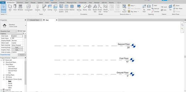
- Rename the Levels as Second Floor by Double Clicking the Text of Level
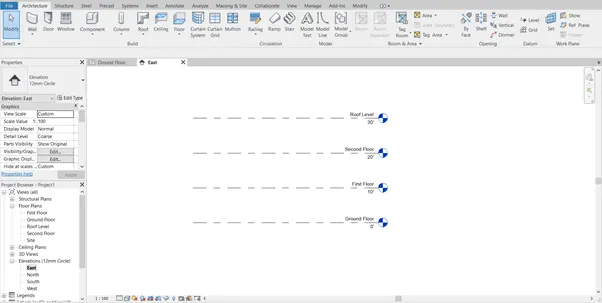
- Similarly Create the Roof Floor By Offsetting 10’ From the Second Floor Level
- Grids: -
- Longitudinal Grids are Drawn From Right to Left 1 to 10 and Transverse Grids From Top to Bottom A to E
- Go to Plan View, in Architectural Tab, Click on Grid
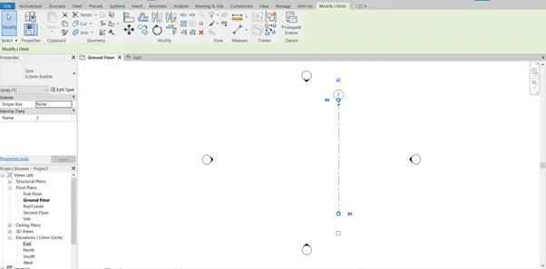
- Click on Line and Draw the Grid Line on the Right Side of the Work Space
- The Grid Number Will be Represented as 1, If Not Double Click and Enter the Value 1.
- Again in Architectural Tab, Click on Grid and Now Select Pick Line and Give the Offset as 20’ and Click on Grid 1.
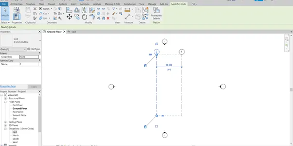
- As the Distance Between the Grid is 20’ Without Moving Out of Command , Click on Grid 2, Thus Grid 3 Will Be Created
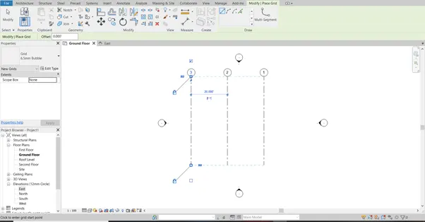
- Similarly Create 10 Grids Lines With Spacing of 20’
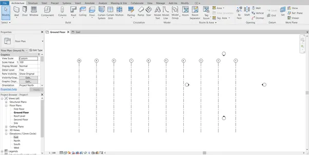
- In Transverse Direction, Drawn a Grid By Line Tool and Mark as A in Top
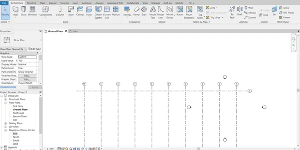
- By Pick Line Give an Offset of 10’ and Click the First Grid
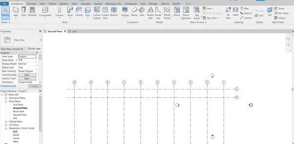
- Similarly Create Up to E Grid
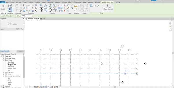
Result: -
5.
Aim: -
- 3D Modelling of Residential Unit
Procedure: -
- Open the New File as Architecture template
- Go to Project Information and Add the Information
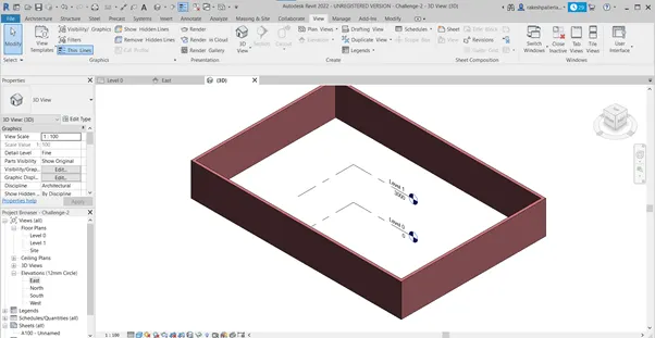
- Click on the Wall in Architectural Tab, In Plan View Draw the Wall
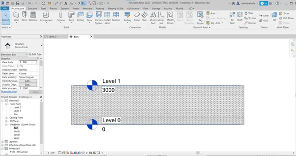
- Select Height and Draw the Wall In Level 0
- Change the Level 1 to 3000mm if it is Not
- Draw the Wall 200 mm Wall, By Clicking I he workspace
Result: -
6.
Aim: -
- Adding Details of Room and Components
Procedure: -
- Select the Previous Created Layout Give the dimensions From the Annotative tab
- Click on the aligned in the annotate tab and Click on the Walls Where the Dimensions is to be Placed
- Placing of Doors
- Click on Door Component from the Architectural tab and Place it Where required
- Select Suitable doors as Per requirement
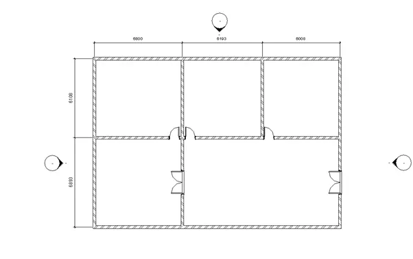
- Placing of Windows
- Click on Windows from the Architectural tab
- Place Suitable Place as Where its Required
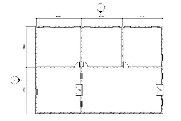
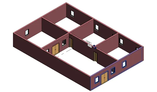
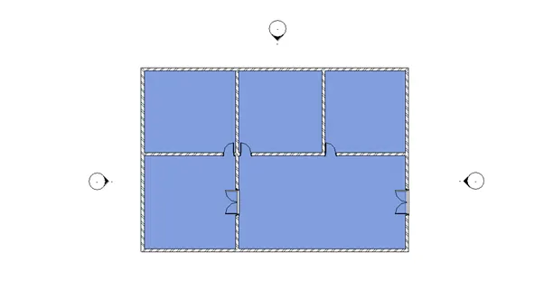
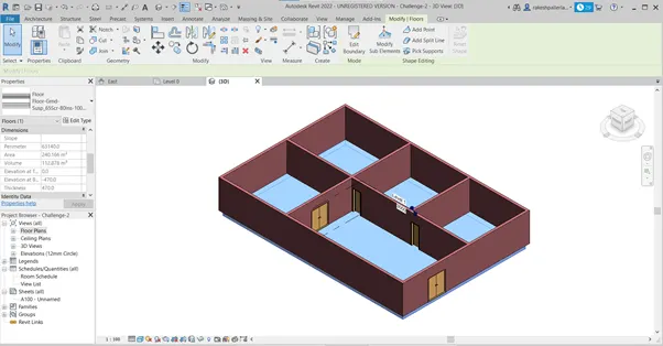
- Creating Floors
- Click on floor Architectural tab and Select the 150 mm Wall
- Select Pick Points and Select the inside of Walls and to Draw Click on Draw line Tool
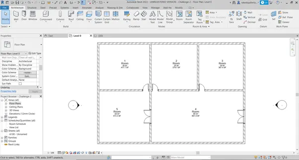
- Rooms Marking: -
- In Architectural Tab Click on Rooms and Place it in Each room
- Double Click the text and Insert the Room name and Size as per Requirement
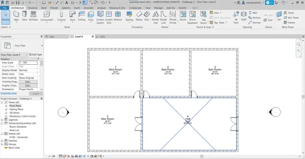
Result: -
7.
Aim: -
- Insert Model Elements to ha Layout
- Doors
- Windows
- Table
- Chair
- Sofa
- Lamp
- Bed
Procedure: -
- Open the previous Selected layout
- Placing of Doors
- Click on Door Component from the Architectural tab and Place it Where required
- Select Suitable doors as Per requirement
- Placing of Windows
- Click on Windows from the Architectural tab
- Place Suitable Place as Where its Required
Inserting Components
- From the Architectural tab Click on Components
- Click on Place a Component if Not Available go to Insert and Click Load Families Select the Components Then Click Open
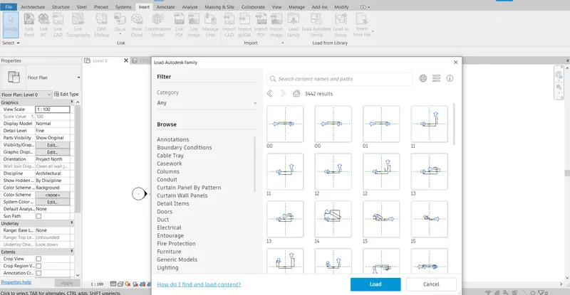
- Select the Component From the Drop down List Place as Per Requirement
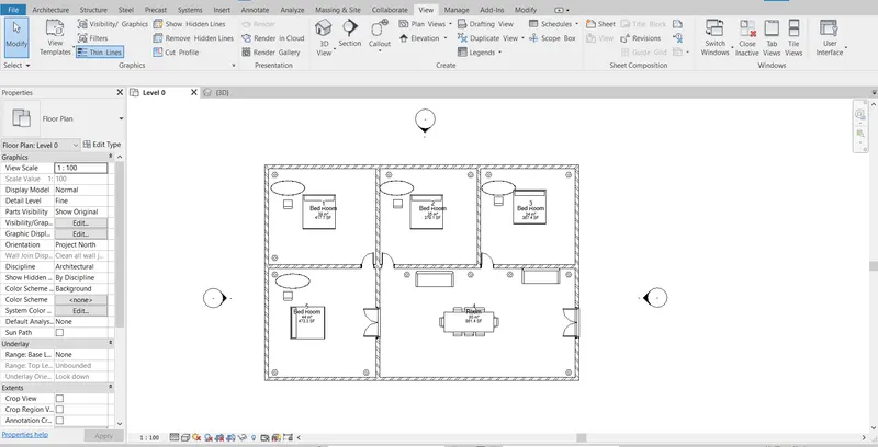
Result: -